handling mechanisms are introduced. system is discussion ... prevailing state of the art in database technology. Since ... either position papers and requirement specifications with little .... information about data definition, for example units in.
An Architecture and Data Model for CAD Databases Alejandro P. Buchmann Conoepoion Perez de Celis /f&WAS - UNAM Notiod University, Meszco Apartado Podtd M-766 Merico, DF., 01000
design CAD system. The resulting architecture, which reflects the diversity of the data to be handled and their usage patterns, will have an effect on the modeling constructs. Molecular objects IBATD84J will be used and we shall present both a high level representation and a possible implementation model for them. The implementation model is important since it will have a major effect on the operators. Finally, a possible option for constraint handling will be outlined. The molecular aggregation model is being developed as part of a project that aims at combining an object-oriented, message passing language, TM IGERM84, BUCA851, with an object oriented DBMS tailored for CAD requirements to form a complete, object-oriented programming environment for CAD.
Abstract An architecture for a process-plant CAD presented to serve as the framework for the of a data model based on the notion of aggregation. Structures, operations and handling mechanisms are introduced.
system is discussion molecular constraint
1.- Introduction Computer Aided Design is emerging as one of the more interesting areas of application for database technology. Unfortunately, there still exists a divorce between the engineering and the database communities. In spite of the early efforts by the engineering community to apply databases to CAD, these were often frustrated by the prevailing state of the art in database technology. Since the database community engaged in CAD-databases many worthwile contributions have been made, but the current literature reflects the present situation: there are either position papers and requirement specifications with little information about possible solutions or one may find specific solutions to smaller subproblems, most of them strongly influenced by VLSI-CAD. While VLSICAD presents important problems there are many other engineering disciplines with requirements that at least match in complexity those of VLSI-CAD. Examples are shipbuilding, chemical process-plant design and aerospace-CAD, to name just a few.
2.- The application realm & environment
Our application realm is chemical process plant design. It is beyond the scope of this paper to present a crashcourse in plant design. For a description of how the engineering design proceeds in this application and how this affects a CAD system the reader can consult IRASH73, LEEM78a, LEEM78b, BUCABO, LEEM82j. Reference to engineering design practice will be made as we explain the architecture. The programming environment is the TM language, which has been described elsewhere IGERM84, BUCA85J. Here we will only summarire its main features to give some additional clues when reading the following sections. TM is an object-oriented, message passing language with data-typing and attribute inheritance. Everything in TM is an object. Objects can be grouped into classes and for each class there exists an administrator. Administrators act upon the members of the class they administer through responses. One of the convenient features of TM is, that responses can be added to an administrator without having to recompile the whole administrator. TM is also extensible in the LISPsense, that is, new modules can be added and once they are accepted the language is considered extended.
We consider it necessary at this time to specify an over-
all systems architecture which truly reflects engineering design practice. This is important since a CAD system and its DBMS will only gain the acceptance of the engineering community if it can support currently accepted design practice. This design practice will have an effect on the necessary modeling constructs, the operators to support them, and the constraints imposed on them. Therefore, we shall present first an overall architecture which was derived from the requirement analysis of a fully integrated industrial scale process plant
proceedings of VLDB 85, Stockholm
the programming
10s
ing to one criterion and any other clustering has to be done through indexing mechanisms.By extracting portions of the global databaseand structuring them according to the prefered accesspaths one can improve response-time markedly. The different levels of data-quality mentioned in the previous section representa third important reason to create subdatabases.
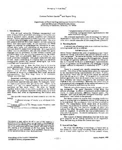
3.-. Gross Architecture: The Databases -Logically one can distinguish the following databasesin a plant designCAD system: * a project-wide approveddatabase; * several workaresdatabases: * a data dictionary and control database; * template and symbol databases; * master cataloguesand support databases; * constraint bases.
So far we have only talked generically about subdatabases. These are actually of three different types basedon their function:
The reasons for separating these databasesis the nature of the data and the kind of operations to be performedon them. We have to handle large amounts of data and of metadata; whether a databasecontains data or metadata is the first criterion for distinction among the databases that were listed above. Secondly, there is the temporality of data, and, finally, the usage patterns, i.e. read and write frequencies,number of users performing accesses, on-line vs. batch updating, archival needs, etc. In the remainder of this section we will analyse the function of each kind of databaseand their interplay. Figure 1 shows these databases and their interaction. 3 1 The project-wide approved database AThe project-wide database is a monotonically growing collection of approved data. In engineering terms, approved data means data that have undergone several levels of verification and authorization, usually by the designer, the group leader, the project manager and the client’s representative. Traditionally, data are always kept on documents and these are legally binding. Any change that is made to approveddata has to be recorded as a revision and the change has to be approvedby the same approval hierarchy. Since a design rarely jumps back and forth between versions it is acceptable that old versions be offloaded in order not to clutter the database. Data that have not reachedfull approval have to be marked so, in order that derived designs be also regarded as tentative and subject to the final approval of the data they were derived from. The sire of the schemais usually a problem, since it comprises of the order of 10,888 attributes. Even if there were no data-quality limitations to updating the full database, the sheer size of the schema and the data volume in a large project make it impossible to allow direct updates to the project-wide databaseother than the integration of final designs. 32 Local and workarea databases A-The length of interactive engineering transactions has been used before as argument for generating subdatabases (HASR82, LORR83). In addition to this rather powerful reason one should not forget the usage patterns of the data, since multiple applications have to accessthe same data. No single database can efficiently support the multiple access paths required. In an object-oriented system, physical clustering will be possible only accord-
106
* local databases; * workareadatabases; * scratchspaces. We have opted for naming them differently to clarify their different functions. However, it is possible to view them all just as workspaces. 3.2.1 Local databases.-
Local databases are extracts from the project-wide approveddatabaseand their content is defined by the application(s) a local database is intended for. The objects to be extracted are determined by the type of the application and by the instance of the application. For example, if a condenser has to be specified it is necessary to extract the already existing data for the heatexchanger(such as heat-duty generated in a processsimulation) and also context data, such as the physical properties of the fluids to be handled, local parameters (e.g. atmospheric pressure) and other project-related information. We call all the data required by an application its context. The local database will be physically restructured basedon access data kept in the data dictionary to optimire performance for a particular application. The local database is a stable copy from which other copies may be generatedthrough simple file copying on demand. This is much faster than carrying out a new extraction from the large project-wide database.Second, in the event a designer decides the design he/she has producedover the last hour is completely messedup, he/ she can start fresh from the stable local database and does not have to undo already committed changes.Finally, it is important to keep in mind the different levels of data quality and the verification process. Often it is easyest to verily a design by reexecuting the consolidated log of the designer’s transaction(s). The consolidated log is the log reducedto only those updateswhich have a lasting effect. If the supervisor discovers mistakes or has a better idea he can put on hold parts of the design he/she is checking. If this is done in the project-wide databaseit can causeserious disruptions. 3.2.2. The workarea databases.- Workarea databases are copies of the local database in which the designer executes the necessarydesign actions. It is possible that two or three designers work in parallel and they may want each their own workarea. Workareas have to be
I I I
1 I I
107
made compatible before integrating them into the project-wide database.
Another class of project specific templates, allthough these are strictly graphical, is the set of allowable symbols.
3.2.3. Scratchspaces.- Often a designer has a wild idea he/she wants to test. Since these ideas may depend on previously executed design actions which are already committed in the workarea,he/she may want to generate one or more ‘what-if’ copies to test different design alternatives. While workareas have to be compatible among them, scratchspacesare usually discarded and at most one is promotedas the correct solution.
Allthough the template databaseand the data dictionary both contain metadata,we consider it important to distinguish them conceptually: the metadata in the data dictionary are fairly stable and reflect an engineering company’s policies. Template data are project-specific and have to be customized for each of an engineering company’s clients. This distinction is important since a major engineering company can have tens of projects active at one time.
3.3 The data dictionary ---
Q Catalogue and support databases
The data dictionary has a double function: during the design of the CAD databasesand during the usageof the system. The database design support data should be readily available to the database designer through a databasedesign tool. However, once the databasedesign is completedthese data can be off-loaded and archived. During operation the data dictionary has to contain the information about data definition, for example units in which the data are stored, the data usageinformation to support the clustering algorithms which determine how the data should be clustered in the local and workarea databases,data mailing lists which are used to support the update propagationmechanismand indicate whether a user has to authorize an update or whether simple notification is enough. The data dictionary will also contain the data usage information about who has checked out what object in order to be able to notify the users of any changethat affects them.
In chemical process plant design one has to handle both one-of-a-kind components,such as the major pieces of equipment, and also standard components. The second class is common for piping components and structural items. For these standard engineering components there exist master catalogues, often produced by the corresponding professional societies. Out of this wealth of possible components it is common to select only a subset which is valid for a given project. This subset, called ‘piping specs’in the case of the piping components, is arrived at through negotiations between the client and the engineeringcompany and is, therefore, project specific. To save time it is also customary to tailor the specsof an old job to the client’s requirements. The piping or other specs are part of a design and can be viewed as value constraints for the standard components. These databases are both a help for the designerso that he can chose valid componentsfrom them and also a source of constraints for the validation mechanism.
u Template database
-3.6 Constraint bases
The lack of unique industry-wide standards forces an engineering company who is contracting for a specific client to adopt that client’s conventions when elaborating drawings or other documents.Each company has its own policy as to format of titleblocks (summary information about a piece of equipment which is included on a drawing), notes, labels, pipe-numbers, etc. This requires a special versatility of a CAD system and its database.A possible solution is through the use of metadata which define for each project the valid templates. These templates can be customixed from a more general template. For example, the titleblock for a pump may consist of an equipment number, an equipment name, a flowrate, the pressure difference between suction and discharge and the specific gravity of the fluid. Some companieswant all this information on a drawing, others prefer only equipment number and its service. If the flowrate is included there is a variety of possibleunits in which it can be displayed(ft**3/sec,gpm,bpd) which could be different from the units in which the data are stored in the database.
Constraint bases are the repositories for constraints and exceptions to these constraints. More detail will be given in Section 8 when we talk about constraint handling. Suffice it to say here that constraints are stored as strings. The string is the description of the constraint and, particularly for project specific cosntraints, the reference values can be taken from the valid support databases. &= Documents
Engineering design is carried through design documents. These documents, who are just different materializations of the data stored in the database have an existence in their own right and the document control information is an integral part of the project-wide database and the workareas. Documentsoften determine an application. For instance, a modification to a processsuch as the inclusion of a new
108
In 1~~~~841 four classes of molecular aggregates were identified and it was shown that all were needed in a complex CAD environment. The classes of molecular and recursive/ aggregates are disjoint/non-disjoint non-recursive. It appears important at this point to mention that non-disjointness can be of two types: a) within one type of molecular aggregate two instances may share an instance of a constituent object; and b) two different molecular aggregates may have the same object as a constituent. Both cases can be handled adequately with this formalism.
piece of equipment is done through the Process FlowSheet. Access control is best implemented through the documents. For control purposes the components of a drawing can be aggregated according to a variety of criteria, such as ‘all the pieces of equipment introduced through a document,‘, ‘all the instruments that appear on a drawing’, etc. Therefore, documents and all the other aggregations defined on them are considered as molecular objects. 52x Molecular
rKg,regation
Disjoint Molecular Aggregates: These occur when all links in a molecular aggregate are 1:N and no cycles are formed. The molecular aggregate is disjoint with respect to other aggregates if no constituent object forms part of another aggregate.
Molecular objects IBATD841 were introduced to allow easy manipulation of aggregates consisting of many, possibly heterogeneous objects. We shall call the basic, non-nested objects, atomic objects, and they are equivalent to the entities in the ER model. Molecular objects are objects of a higher degree of abstraction and can consist themselves either 01 atomic objects or other molecular objects of lesser degree of abstraction. The process by which molecular objects are formed is called molecular aggregation.
Non-Disjoint Molecular Aggregates: Internal non-disjointness occurs when at least one link is M:N; external non-disjointness occurs when at least one constituent object in the aggregate is also a constituent object of another aggregate.
In order to describe a schema adequately it is necessary to be able to express it in the form of a language. Therefore, a definition is needed that can easily be expressed as a language, as opposed to purely graphical structures. The DDL constructs will be presented elsewhere.
Recursive Molecular Aggregates: There exists at least one link that originates and ends with the same object LYPe. Non-Recursive Molecular Aggregates: There exists no link that originates and ends with the same object type.
A molecular aggregate can be defined with very few concepts: objects and links. We avoid the term ‘role’ consciously, although the links carry the semantics of the association, because the notion of object-role has a definite meaning in Falkenb-erg’s object-role model (FALE’IBJ. Molecular aggregates do not impose the limitations of the object-role model.
This simple but yet powerful definition of molecular aggregation leads us directly to an implementation model hased on binary relations.
6.- Implementation model for rsg(reKates The implementation model that underlies the discussion of the operators is quite simple: every record or atomic object (equivalent to entities in the ER sense) has its unique internal id. Aggregates are formed through binary relations of the internal ids of the records involved. The binary relations can be easily held in a B-tree and can also be compressed [BUCA831.
A molecular aggregate is the set, MA = { {objects},{links} } where the objects in the set of objects can be either atomic objects or molecular objects themselves. The links are the roles under which the objects are linked within that particular molecular aggregate. Then, a molecular aggregate will just be the set of triplets of the form (Mi,Oj,Lk). There exist situations in which L is the same for all triplets, for example, ‘component of’ relationships. fn other cases, different aggregation roles L can appear in the triplets that form a molecular aggregate. An example of this caseis a flowsheet-drawing for which we want to identify those pieces of equipment that were newly introduced to the design through this particular drawing and also want to specify all the pieces of equipment that appear on the drawing, regardless of whether they existed before or not. Molecular objects are layered and have one molecular reference level which can have its own aggregate attributes and the constituent objects.
This storage structure has definite advantages: no pointer space has to be reserved in advance, no foreign key attributes have to be defined, aggregates can be crested dynamically from already existing records. The use of binary relations also offers some distinct advan@es over n-ary relations: deep component hierarchies can be represented economically without repeating the id of the uppermost records, binary relations are easily COmpreSSd and no problems with null values arise in the linkage relations since a component object is only connected when it is instantiated or after the database has been populated. For the first implementation we are restricting OUR3dveS to binary relations because of their simplicity and
109
becausewe have already developedsoftware for efficient handling of binary relations. If irreducible n-ary relations are needed by the applications, then we can expand the system, but this means that some of the operatorswill have to be redefined. 7.- Operators
For a data model to be useful beyondthe highest level of conceptual modeling it is necessaryto specify operations that are permitted on the data structures. We shall discuss here operations for aggregation,i.e. the formation and population of molecular objects, insertion and deletion within a single database, and extraction and reintegration operationsamong the project-wide and workareadatabases specifiedin the overall architecture. 7J Aggreagtion operations Severalcasesof molecular aggregationcan be identified: 1) The definition of the molecular object exists and it is formed upon insertion of the instances of the componentobjects. 2) The definition of the molecular object exists in generic terms but it is only instantiated once the values for the aggregation criterion have been specified. Once the criterion has been specified, the molecular object is instantiated from already loadedinstancesof the componentobjects. 3) The definition of the molecular object does not exist and has to be created and registered first. Once it has been accepted by the system the molecular object can be instantiated according to the criteria of the previous case. 7.1.1 Aggregation upon insertion. This case requires that first the identifier for the molecular object be inserted (the attributes of the molecular object are optional). Then the mapping between the molecular level and the component objects is established for each triplet (molecule(i), object(j), link(k)) as a function of link(k). Two subcaseshave to be distinguished:
In addition to this automatic linking there is the needfor conditional linking at the moment of storage, for instance depending on an existence criterion. An example is the aggregationformed under the role ‘all the equipment first introduced through an application’. In this case, first the existence of the present instance of equipment has to be tested, if it fails, the aggregation proceeds and an id-pair is introduced in the binary relation representing the ‘first introduced’ role. If existence is true, no aggregationoccurs. This is rather an insertion operation. 7.1.2 Aggregation after loading. A posteriori population of a molecular object, is more interesting. Assume the databasehas already been populatedwith piecesof equipment, pipelines, valves, instruments, etc. during the design tasks leading up to the Piping and Instrumentation Diagram level. After the initial layout new units are created based on spatial boundaries and assigned to different designers. The generic criterion of subdivision is already known and used in the definition of the molecular objects representing these new units but the exact values are only providedlater. The actions to be taken are then: scanning of the instances of the component objects and insertion of id-pairs into the binary relation corresponding to the specifiedaggregationrole. 7.1.3 Dynamic definition of aggregates. This case is included for flexibility and can arise when a designer wants to group according to an aggregation role not contemplated before. An example could be the definition of the ‘cooling water network’ or any other criterion which may have only temporal validity. The actions to be taken are: definition of the new molecular object, instantiation of the molecule’s id, creation of a new binary relation representing the role of aggregation and then the actions of case 2. Should the necessarydata for the evaluation of the aggregation criterion not be available in the database, then manual linkage is possible. The proposedstorage structure supports this case since no external attributes have to be defined in the constituent records nor is it necessary to reserve additional pointer spacewithin the componentrecords. As a corollary one can postulate that a good database design will anticipate the required aggregations and, therefore, can define them in the schema and does not need a dynamic schema definition capability. However, since a database designer who is really conversant with the application seems to be rare, and because of the desirability to define non-essential but convenient aggregates dynamically, this option is supported since it is associatedwith little overheadin this model.
* The binary relation representing link(k) already exists, in which case only a new instance of the pair (Mid,Objectid)is inserted. * The binary relation representing link(k) does not exist already, in which case the binary relation is first instantiated and then the id-pair is inserted. An example of case 1 could be a drawing and every instance of an object used on it, like piecesof equipment, is automatically linked to the drawing.
110
Q Insertion
operations
Insertion can be of two kinds: insertion of atomic objects, in which case no further action has to be taken, or insertion of atomic objects belonging to a
to be issued. The actions here require that all molecular objects that include the object to be deleted be traced and receive a message, so that the object can be disconnected from those molecular objects. Once it is disconnected from all other molecular objects, then the one issuing the ‘intention to delete’ can actually proceed and drop it. At a first glance, this procedure appears to be cumbersome but it corresponds to engineering design practice and avoids that objects simply vanish and leave holes in other portions of the design, particularly in those cases were one object can have different representations. In addition, this procedure is mostly applicable at the project-wide database level. Within the workareas, where most deletions occur, this situation will arise rarely.
molecular object. In this case insertion consists of the actions described above under aggregation operations (automatic and conditional). Insertion is always carried out first in a workarea database which is an extraction from the project-wide database (see 7.4). If an object is to be inserted but it exists already, then the extraction mechanism can be invoked to avoid redundant insertions. ‘7.3 Deletion operations Deletion operations become difficult in the moment one accepts non-disjoint molecular objects. We distinguish three cases: 1) Elimination of 2) Elimination component of a 3) Elimination of
a free-standing atomic object. of an atomic object that is a molecular object. a
7.3.3 Elimination of a molecular object. Elimination of molecular objects can be of two types: the molecular object is not part of another molecular object, or it is part of another molecular object.
molecular object.
7.3.1 Elimination of free-standing atomic objects. This
The first case implies that the label portion of the molecular object be deleted as well as all the instances of id-pairs in which the id of the molecular object appears. Depending on the aggregation roles, this means that component objects with no existence of their own (weak entities) be deleted as well. An example of this case is the elimination of a pipeline. Eliminating the pipeline means also eliminating its components, such as valves, fittings, pieces of pipe, etc. However, it is important to realize that the necessary checks have to be performed in order not to leave other pipelines dangling or a pump discharging into the air.
operation is straightforward and consists only in eliminating an instance of the object. However, in order to know whether an object is a free-standing atomic object it is necessary to check in the dictionary the definitions of the molecular objects to see whether an atomic object is part of any molecular object. This information can either be held at the TM dictionary level or at the data dictionary level, whichever proves more efficient. Like any other deletion operation, freestanding atomic objects can only be eliminated through the application by which they were created.
The second case, elimination of a molecular object which is part of another molecular object, has to be treated first as if the molecular object was a component atomic object. Once the ‘intention to delete’ has cleared, then the case is reduced to the elimination of a noncomponent molecular object. The ‘intention to delete’ has to trigger the update propagation mechanism that alerts other users who may be affected. An example of this case is the deletion of a valve that is a component in a pipeline. The valve itself is a molecular object with its own components. The initial clearing process is used to alert the affected parties, that they may have to perform some adjustments manually. If the valve is eliminated at the piping and instrumentation level and the deletion is automatically propagated, it may leave a hole in the pipeline and it requires replacing two pieces of pipe and flanges explicitly by a new, single piece of pipe. These changes involve design decisions and should not be carried out automatically. There is no effect whether a molecular object is is recursive or non-recursive, since recursivity meaningful mostly for modeling purposes. For implementation we have distinct objects but of the same type.
7.3.2 Elimination of a component atomic object. This deletion operation has two subcases which have their nature in the way engineering design is done. For each design object there exists one responsible person or group, usually the one who introduced that object. Therefore, this person or group is the only one authorized to kill or eliminate that object from the database. Everybody else can use that object and manipulate it, some can update it or specify additional detail, but they cannot delete it from the database. Therefore the two subcases are: 1) Deletion of an object by a non-creator. 2) Deletion of an object by its creator. Deletion of an object by a non-creator of that object is strictly a disconnection from the molecular object that had this atomic object as a component. The action to be taken is the elimination of the corresponding id-pair from the binary relation representing that role. Deletion of an object by its creator means eventually the actual elimination from the database. However, this cannot occur without warning to those responsible for molecular objects that use the atomic object to be deleted. Therefore, first an ‘intention to delete’ has
111
parallel to semantic nets ILEVH791 and it is worthwile exploring how more complex operations can be integrated as programs.
7.4 Extraction -and Reintegration ..Extraction and reintegration are two operations that involve more than one database. We will use here the relationship that exists between the project-wide database and a local database.
&= Constmint
Hmdlin~
A large portion of a design engineer’s time is spent applying constmints. These constraints can take the form of design codes, such as TEMA for heakxchangers or ASME Section VIII for pressure vessels, passing through the constraints set down in the piping or structural specs to rather ill-defined rules of thumb and company or personal preferences. It is in these constraints were much of engineering knowledge is stored. It is safe to assume that it is impossible to specify all constraints up-front, i.e. during design and start-up of a CAD system. Therefore, we need a system that allows us to define constraints dynamically. Since constraint checking is rather time-consuming and often long response times disrupt a designer’s train of thought it is necessary that constraint checking operaks on request. In our proposed architecture the constraint verification will intervene at the local level when a designer wants to check his/her design, at the supervision stage during approval and at a global level upon reintegration of an object into the project-wide database. Another necessary capability is exception handling. Engineering design criteria consists in weighing contradictory often selecting a solution that may violate one or several constraints. The system must be able to register these exceptions and not block progress everytime it comes to that conscious constraint violation. However, at the approval stage it must flag any exception.
7.4.1 Extraction. The extraction operation allows us to establish a local database that contains all the necessary data to work on a specific application (or several of them if we specify them). The necessary data for an application is the context and was explained previously. It is kept as part of the data dictionary, were it should have been gathered during the database design phase. (Our database design tool jBUCA821 contains some basic information on data usage and we are expanding it to handle molecular aggregates.) The actions to be executed are: Given the context the follow specification in the data dictionary, necessary links and extract the required instances. Use the heuristics from the data dictionary to determine the best clustering for the application and genera& a new local database with the extracted data in the preferred clustering and with the necessary access paths. Mark all the objects in the project-wide database that were extracted, so that any update can be propagated. Extracted objects remain in the project-wide database and are available to other applications. Extraction has a variant that is invocated when we try to insert a new object. In order not to introduce objects into a workarea in duplicate form, the insertion process can verify first the existence of the object in the project-wide database. If it exists, then that object is extracted and inserted into the local and workarea databases.
A quick glance at the types of constraints we have to handle shows us that we can distiguish between: * * * * *
7.4.2 Reintegration. Reintegration is the process by which an object that was either modified or freshly inserted into a workarea database is transfered to the project-wide database after it has been approved.
type checking constraints; property inheritance constraints; range checking constmints; value matching constraints; consiskncy constraints.
Type checking is done in our environment at the TM language level, which serves as a homogeneous language for data definition, data manipulation and application programming. The language provides for class definition which may be of any complexity, allowing for nested objects. This type-checking mechanism can be applied here. The property inheritance constraints are also handled by the language’s class definition capability.
The actions to be executed are: First the inkntion to reintegrate is declared. This intention puts a lock on the object in the project-wide database, so that no new extractions can be carried out. Once the lock has been granted, the update is broadcast to those users in whose context that object appears while the update is queued waiting for the OK from affected users. Then the update is carried out in the database freeing the object again for new extractions.
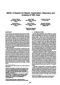
What we shall describe with some more detail is the constraint handling mechanism for range checking, value matching and consistency constraints. Figure 2 shows schematically the components of the constraint handling mechanism and their function. The constraint handling mechanism consists of the Constraint Handler, an Exception Definition Module and Constraint Bases for and Constraints Privak Constraints, Universal
7.5 Other operators -It is interesting to observe that in object-oriented systems like TM everything is an object. Programs can be grouped into classes which are themselves administered by an administrator. This is an interesting
112
Exceptions. Table 1 illustrates these constraints. For example, a universal range checking constraint would be (0 4 x 4 1) where x is a mole lrsction. On the other hand it is general practice that water be never allowed in a heatexchanger to exceed 120 degrees F (a universal constraint). However in a plant where the water has a high cardonate concentratibn it may be necessary to restrict the temperature to 100 degrees F to avoid scaling. This would be a private constraint that only applies to this project. An exception could be that in spite of the private constraint limiting temperatures to 100 degrees in Chat plant, for a certain application it is justifiable to allow 110 degrees F. Similarly, for value matching one can identify the universal constraint as all the pipe schedules available. A private constraint taken from the pipe spec may indicate that only pipes of schedule 40 and 80 are allowed. Consistency constraints involve two or more database attributes or objects and can be of any degree of complexity. Here we show only the consistency relationship between design and operating pressures.
Exceptions have both a new constraint value and a realm of
applicability.
For
instance,
we may change the
maximum water temperature to 110 degrees F (the new constraint) for a specific exchanger or an entire plant (the realm of applicability).
Table 1: Examples of Cons!raints
Constraints are associated with database objects. However, since the constraints are only to he invoked upon demand, we consider it useful Co keep the constraints in separate constraint bases. This has the added advantage, that we can substitute sets of constraints, particularly those that are project-specific. For example, a vessel can be designed according Co ASME Section VIII or according to DIN standards. In addition, a company may have its own design norms. The mechanism we are proposing allows us Co use for one project one code and for another project the other. In addition, we can specify more than one constraint base to be active at a given time. This mechanism permits to enforce the more restrictive set of norms on Cop of the industry-wide design norms. The constraint handler, if activated, will check first in the private constraint base, since this is the more restrictive. If no violation occurs the database action can proceed. If a violation occurs, the exception base is checked. If an exception exists and is fulfilled processing proceeds, if it does not exist the user is asked to define an exception which is then registered and stored or to change his action on the database. If no private constraint exists, the universal constraint base is checked following the same steps as in the previous case. This strategy reduces constraint base accesses CO a minimum.
Proj. Spec.
Tcm, < 100°F
Exception
T-1 < 1lO’F
t0n5:,. Honaltr
TM allows Chat an administrator receives a string which is interpreted and executed. This allows us to store constraints as strings. When the constraint handler gets it, he executes it, possibly invocating other administrators (i.e. the class code associated with a class of objects). For each constraint a particular action is required. This means that new constraints require new responses. The response-adding mechanism of TM, mentioned in Section 2 and explained in [GERM841, allows us to add new constraints and their responses dynamically.
113
4030
120,Plant A
PD> 1.1 Pop PD >1.05Pop
9.- Current ---w-P
Strtus rnd Future Work
The language TM is currently undergoing its third experimental implementation and work is underway to include necessarydatabase constructs. The CAD system outlined in this paper will serve as a test for the language and as a source for expansion of its capabilities. The database portion is in the design phase and work is proceeding in the definition 01 the DDL of molecular objects, storage structures for molecular objects, clustering criteria based on access patterns obtained from a database design tool, and the implementation of the constraint handler in primary storage only at this time. The present report is only a general overview and further work is neededin the areas listed above.
Modelling (FALE761Falkenberg,E.; ‘Concepts for Information’, in ‘Modeling in Data Base Management Systems’, G.M. Nijssen (ed.), North Holland Publ. Co., 1976. IGERM84)Gersso,J.M., Buchmann,A.P.; ‘TM - An Object Oriented Languagefor CAD and Required Database Capabilities’, IEEE Workshop on Languages for Automation, New Orleans,Nov. 1984. (HASR82)Haskins,R., Lorie,R.; ‘On Extending the Functions of a Relational Database System’, ACM SIGMOD 1982,pp 287-212. (LEEM78aJ.,eesley,M.E., Buchmann,A.P.; ‘Databases for Process Plant Design’, Prcc. CAD78 Brighton, England, March 1978.
Acknowledgements
(LEEM78bLeesley,M.E., Buchmann,A.P, Mulraney,D.D.; ‘An Approach to a Largely Integrated System for Process Plant Design’, Proc. International Conference on Contributions of Computers in Chemical Engineering,Paris, France, March 1978, Vol. E, p. 146-152.
Special thank is due to Mike Gerxso, the designer of the TM language. Gratitude is expressed to Autotrol and Michael Leesley Consulting Inc. There the interaction with Dan Radin, Rex McDonnel, Bob Donaldson,George Osborne and many others proved very useful. Many of the ideas for the architecture and insights into actual design practice stem from that interaction. The initial notions of molecular aggregation evolved out of long discussionswith Don Batory at the University of Texas. Last but not least thank is due to the membersof the CAD group at IIMAS, particularly Roland0 Carrera, for valuable input.
ILEEM82)Leesley,M.E. (ed); ‘CAD of Chemical Process Plants’, Gulf Publ. Co., Houston, 1982. lLEVH791Levesque,H.J., Mylopoulos,J.; ‘A procedural semanticsfor semantic networks’,in ‘Associative Networks’, N. Findler (ed.), pp 93-120,Academic Press,NewYork. ILORR831Lorie,R., Plouffe,W.; ‘Complex Objects and their Use in Design Transactions’ Proc. 1983 ACM Engineering Design Applications, San Jose,Cal., May 1963.
References
(RASH’IB]Rase,H.F.; ‘Project Engineering of Plants’, John Wiley, 1976.
IBATD84]Batory,D.S.,Buchmann,A.P.; ‘Molecular Objects, Abstract Data Types and Data Models: A Framework’, 10th Intl. Conf. on Very Large Data Bases,Singapore,Aug. 1984.
Process
IBUCA8OJBuchmmn,A.P.; ‘A Methodology for the Logical Design of Project Engineering Databases,PhD Thesis,The University of Texas, Austin, 1986. IBUCA821Buchmann,A.P.,Leesley,M.E., Dale,A.G.; ‘The Role, Structure and Design of a Database for Dissemination of Process Data during Plant Design’, Chem. Eng. Comm., Vol. 16, pp l-37, 1982. Permission to copy without fee all or part of thii material is granted provided that the copies are not made or distributed for direct commercial advantage, the VLDB copyright notice and the title of the publication and its date appear, and notice is given that copy ing is by permission of the Very Large Data Base Endowment. To copy otherwise, or to republish, requires a fee and/or special permission from the Endowment.
IBUCA85)Buchmann,A.P.,Gerrso,J.M.; ‘Handling HeterogeneouslyFormatted Data in an Object-Orientec Database Environment for CAD’, Compute: Graphics85, NCGA, Dallas, April 1985.
114