An Efficient Computation of Handle and Tunnel ... - Siggraph 2013 [PDF]
Recommend Documents
Jul 23, 2016 - 8:30 am - 3:30 pm. Center/SIGGRAPH .... 6 - 8 pm. FP F S EP E. VR Village noon - 5:30 pm. 10 am - 5:30 pm
May 27, 2004 - for design and construction. ... The construction of the tunnel, starting from the first design stage to the ..... Barton N., Lien R. and Lunde J., 1974.
Jul 23, 2016 - Course: The Quest for the Ray Tracing API. 9 am-5:30 pm ... Studio Workshop: Android VR. Development ....
Jul 29, 2016 - Compute Cloud for Rendering â Big Studio ...... the Android platform by adding advanced computer .....
Jul 29, 2016 - Many SIGGRAPH 2016 programs and events are assigned to focused areas of interest in ...... specifically f
Aug 27, 2014 - Research Article. An Efficient Computation of Effective Ground Range Using ... The effective ground range of a ballistic missile is an arc-length of a planner ...... missile defense,â Infrared Physics and Technology, vol. 42, no. 3â
Hai H. Dam, Kamran Shafi, Hussein A. Abbass. School of Info. Tech. and Electr. Eng. Univ. College, Univ. of New South Wales. ADFA, Canberra ACT 2600.
type represents a general curve that may be self-intersecting and can comprise ...... Pentium IV machine with 2 GB of RA
1 Introduction. Many applications such as topology repair of 3D models [Bischoff ... fit from automatic detection of loops on surfaces that are associated with features ... restriction on the class of input 3D models as in some of the earlier works.
a planar point, representing a curve endpoint or an intersection between two curves (or more), and ... 2See the CGAL pro
Connect with people from everywhere in the world who share your joy in the power of art and science. ...... Tangible and
Jul 29, 2017 - Adobe Systems Incorporated. Jonathan ...... facial AI deep learning, and advanced real-time ...... Brushe
nvFX: A New Shader-Effect Framework for OpenGL and OpenGL Compute and
other ... Books. - New Red Book (OpenGL Programming Guide) - March 2013.
Sep 12, 2015 - systems and found, for example, in grid services can hinder efficiency in service quality and ... https://ggus.eu/ws/ticket_info.php?ticket=8843 shows an example of ticket issued .... and that can support incremental computing.
Sep 11, 2006 - Pm(x) = x3 â mx2 â (m + 3)x + 1 and Pm(x) = x4 â mx3 â 6x2 + mx + 1. We give explicit formulas for powers of the Gaussian sums attached to ...
May 21, 2004 - INSTITUTE OF PHYSICS PUBLISHING ... Efficient computation of lead field bases and influence ... algorithms for their efficient computation.
Jul 21, 2011 - nates to compute efficiently the Castelnuovo-Mumford regularity of a homo- geneous ideal. ...... [3] David Bayer and Michael Stillman. A criterion ...
Apr 28, 2006 - We focus on systems with parts that have a significant rotational speed. An important ... in the case that gravitational forces can be neglected. ... turbines, compressors, pumps, helicopters, gyroscopic wheels and computer hard ... ai
computation of short addition chains. Our method is based upon continued fraction expansions. Most of the popular methods for the generation of addition ...
Apr 13, 2010 - order, and the remaining rows are each cyclic permutations of the last row. The eigenvectors of a circulant matrix of a given size are the ...
conciseness: Is the set of all substrings S(D) concise enough so as to be useful ..... $1 d a b. $2. 2, 1. 1, 1. 2, 2. 1, 2. 1, 0. 3, 1. 2, 0. 3, 0. $1 b a c b. $3. $2. $1.
Mar 3, 2015 - The analysis of complex systems frequently poses the challenge to distinguish correlation from causation. Statistical physics has inspired very ...
Jul 29, 2017 - Course: Applications of Visual Perception to. Virtual Reality ...... online and mobile apps for color ana
Courses ranges from an introduction to the foundations of computer graphics and interactive techniques for those new to
An Efficient Computation of Handle and Tunnel ... - Siggraph 2013 [PDF]
... 3D tessellation. This saves time considerably for large meshes making the algorithm ..... 3D graphics files, version control is commonly used to maintain multiple versions ...... sentation as an Adobe Illustrator plug-in that allows even inexperi-.
An Efficient Computation of Handle and Tunnel Loops via Reeb Graphs∗ Tamal K. Dey† The Ohio State University, U.S.A
Fengtao Fan‡ The Ohio State University, U.S.A
Yusu Wang§ The Ohio State University, U.S.A
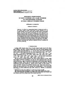
Figure 1: (a) – (d) shows the pipeline of our algorithm: (a) The height function on the input surface. (b) Reeb graph w.r.t. the height function. (c) Initial handle and tunnel loops. (d) Final handle / tunnel loops after geometric optimization. (e) The output is stable under noise.
Abstract A special family of non-trivial loops on a surface called handle and tunnel loops associates closely to geometric features of “handles” and “tunnels” respectively in a 3D model. The identification of these handle and tunnel loops can benefit a broad range of applications from topology simplification / repair, and surface parameterization, to feature and shape recognition. Many of the existing efficient algorithms for computing non-trivial loops cannot be used to compute these special type of loops. The two algorithms known for computing handle and tunnel loops provably have a serious drawback that they both require a tessellation of the interior and exterior spaces bounded by the surface. Computing such a tessellation of three dimensional space around the surface is a non-trivial task and can be quite expensive. Furthermore, such a tessellation may need to refine the surface mesh, thus causing the undesirable side-effect of outputting the loops on an altered surface mesh. In this paper, we present an efficient algorithm to compute a basis for handle and tunnel loops without requiring any 3D tessellation. This saves time considerably for large meshes making the algorithm scalable while computing the loops on the original input mesh and not on some refined version of it. We use the concept of the Reeb graph which together with several key theoretical insights on linking number provide an initial set of loops that provably constitute a handle and a tunnel basis. We further develop a novel strategy to tighten these handle and tunnel basis loops to make them geometrically relevant. We demonstrate the efficiency and effectiveness of our algorithm as well as show its robustness against noise, and other anomalies in the input. CR Categories: I.3.5 [Computer Graphics]: Computational Geometry and Object Modeling—Geometric algorithms, languages, and systems ∗ Omitted proofs can be found in a supplementary material available from
The computation of topologically non-trivial loops on a surface embedded in three dimensions appears as a sub-step in many geometry processing applications. These applications generally benefit greatly if the non-trivial loops encode geometric features such as ‘handles’ and ‘tunnels’ of the 3D model. The non-trivial loops that identify such features are of great interest in topology repair [Bischoff and Kobbelt 2005; Zhou et al. 2007]. If these features appear as spurious, it is desirable to eliminate them so that they do no interfere with further processing. In surface parameterization [Ben-Chen et al. 2008; Gu et al. 2002; Sheffer and Hart 2002], the input surface mesh needs to be cut along non-trivial loops into a flat disk. This again benefits from the detection of loops that are small around ‘handles’ and ‘tunnels” because the side-effect of boundary caused by cutting along such small features remains small. Feature recognition and shape correspondence [Biasotti et al. 2008; van Kaick et al. 2010] are key problems in various applications which clearly benefit from localizing the features to loops that are associated with ‘handles’ and ‘tunnels’ [Dey et al. 2008].
ACM Transactions on Graphics, Vol. 32, No. 4, Article 32, Publication Date: July 2013
Robust Inside-Outside Segmentation using Generalized Winding Numbers Alec Jacobson1
Ladislav Kavan2,1 1
Input mesh
ETH Zurich
Winding number in CDT
2
Olga Sorkine-Hornung1
University of Pennsylvania
Surface of segmented CDT Slice through volume
Refined tet mesh
Figure 1: The Big SigCat input mesh has 3442 pairs of intersecting triangles (bright red), 1020 edges on open boundaries (dark red), 344 non-manifold edges (purple) and 67 connected components (randomly colored). On top of those problems, a SIGGRAPH logo shaped hole is carved from her side.
Abstract Solid shapes in computer graphics are often represented with boundary descriptions, e.g. triangle meshes, but animation, physicallybased simulation, and geometry processing are more realistic and accurate when explicit volume representations are available. Tetrahedral meshes which exactly contain (interpolate) the input boundary description are desirable but difficult to construct for a large class of input meshes. Character meshes and CAD models are often composed of many connected components with numerous selfintersections, non-manifold pieces, and open boundaries, precluding existing meshing algorithms. We propose an automatic algorithm handling all of these issues, resulting in a compact discretization of the input’s inner volume. We only require reasonably consistent orientation of the input triangle mesh. By generalizing the winding number for arbitrary triangle meshes, we define a function that is a perfect segmentation for watertight input and is well-behaved otherwise. This function guides a graphcut segmentation of a constrained Delaunay tessellation (CDT), providing a minimal description that meets the boundary exactly and may be fed as input to existing tools to achieve element quality. We highlight our robustness on a number of examples and show applications of solving PDEs, volumetric texturing and elastic simulation. Keywords: winding number, tetrahedral meshing, inside-outside segmentation Links:
DL
PDF
W EB
V IDEO
physically-based simulation of a hippopotamus would look quite different (and unrealistic) if handled as a thin shell, rather than a solid. Since many operations in animation, simulation and geometry processing require an explicit representation of an object’s volume, for example for finite element analysis and solving PDEs, a conforming1 tetrahedral meshing of the surface is highly desired, as it enables volumetric computation with direct access to and assignment of boundary surface values. However, a wide range of “real-life” models, although they appear to describe the boundary of a solid object, are in fact unmeshable with current tools, due to the presence of geometric and topological artifacts such as self-intersections, open boundaries and non-manifold edges. As a consequence, processing is often limited to the surface, bounding volumetric grids [McAdams et al. 2011] or approximations with volume-like scaffolding [Zhou et al. 2005; Baran and Popovi´c 2007; Zhang et al. 2010]. The aforementioned artifacts are common in man-made meshes, as these are the direct output of human creativity expressed through modeling tools, which very easily allow such artifacts to appear. Sometimes they are even purposefully introduced by the designer: for example, character meshes will typically contain many overlapping components representing clothing, accessories or small features, many of which have open boundaries (see Figure 2). Modelers 1 Contrary to some authors’ use of “conforming” to mean that every mesh edge is locally Delaunay, we use it simply to mean that the volume mesh interpolates to the boundary description.
DATA
Input mesh
1
Slice in output volume
Introduction
A large class of surface meshes used in computer graphics represent solid 3D objects. Accordingly, many applications need to treat such models as volumetric objects: for example, the animation or
Figure 2: Each whisker, tooth and eye of the Big SigCat is a separate component that self-intersects the body. ACM Transactions on Graphics, Vol. 32, No. 4, Article 33, Publication Date: July 2013
Putting Holes in Holey Geometry: Topology Change for Arbitrary Surfaces Gilbert Louis Bernstein∗ University of Washington Stanford University
Chris Wojtan† IST Austria
Figure 1: This zombie model (a) has numerous open surfaces, non-manifold edges, and self-intersections, displayed in red here (b). Nonethe-less, using the technique described in this paper, we are able to (c) poke through the zombie’s chest and (d) create the desired tunnel/hole.
Abstract This paper presents a method for computing topology changes for triangle meshes in an interactive geometric modeling environment. Most triangle meshes in practice do not exhibit desirable geometric properties, so we develop a solution that is independent of standard assumptions and robust to geometric errors. Specifically, we provide the first method for topology change applicable to arbitrary non-solid, non-manifold, non-closed, self-intersecting surfaces. We prove that this new method for topology change produces the expected conventional results when applied to solid (closed, manifold, non-self-intersecting) surfaces—that is, we prove a backwardscompatibility property relative to prior work. Beyond solid surfaces, we present empirical evidence that our method remains tolerant to a variety of surface aberrations through the incorporation of a novel error correction scheme. Finally, we demonstrate how topology change applied to non-solid objects enables wholly new and useful behaviors. CR Categories: I.3.7 [Computer Graphics]: Computational Geometry and Object Modeling—Geometric algorithms, languages, and systems; Keywords: topology, intersections, deformations, sculpting, 3d modeling, non-manifold geometry Links:
1
DL
PDF
W EB
V IDEO
Programs for the 3d modeling of surfaces must support ways to change the topology of a surface or else be severely limited in their capabilities. For instance, without some way to edit or change the † e-mail:
While the ability to change topology is critical for all 3d modeling software, strategies vary widely depending on the representation of the surface and the modeling paradigm in use. For instance, in traditional CAD-derived modeling software like Maya [2013b], or 3DS Max [2013a], special tools allow the user to directly edit the connectivity of the polygons comprising the mesh. Sketch-based modelers in the vein of Teddy [Igarashi et al. 1999] incorporate special stroke gestures which allow users to add tunnels or handles to a surface. Meanwhile voxel-based modeling, exemplified by 3D Coat [2013] or the game Minecraft [2013], naturally incorporates changing topology as a by-product of the representation. In this paper we propose a novel method for supporting topology change in surface-deformation modeling software (e.g. Zbrush [2013b], Sculptris [2013a], Mudbox [2013c]). Like voxel modeling, we would like our topology change to be incidental, occurring as a natural side effect of using existing tools/brushes. In contrast, note that CAD-like and sketch-based modelers require specialized tools for topology change. By choosing incidental topology change over specialized tools, we can achieve greater parsimony (§8) in our modeling system.
C ODE
Introduction
∗ e-mail:
topology of a surface, it is impossible to model a donut starting from a sphere. The ability to model changes in topology is also critical for the assembly of surfaces from parts, as well as permitting surfaces to merge or split as they are manipulated, to name just a few more consequences.
ACM Reference Format Bernstein, G., Wojtan, C. 2013. Putting Holes in Holey Geometry: Topology Change for Arbitrary Surfaces. ACM Trans. Graph. 32, 4, Article 34 (July 2013), 11 pages. DOI = 10.1145/2461912.2462027 http://doi.acm.org/10.1145/2461912.2462027. Copyright Notice Permission to make digital or hard copies of all or part of this work for personal or classroom use is granted without fee provided that copies are not made or distributed for profit or commercial advantage and that copies bear this notice and the full citation on the first page. Copyrights for components of this work owned by others than the author(s) must be honored. Abstracting with credit is permitted. To copy otherwise, or republish, to post on servers or to redistribute to lists, requires prior specific permission and/or a fee. Request permissions from [email protected]. 2013 Copyright held by the Owner/Author. Publication rights licensed to ACM. 0730-0301/13/07-ART34 $15.00. DOI: http://dx.doi.org/10.1145/2461912.2462027
Having made the choice to incorporate topology change incidentally, a number of methods for topology change primarily used in the simulation literature are available to us [Wojtan et al. 2009; Brochu and Bridson 2009]. Unfortunately, these methods all require that the surface represents a solid object—one that can be faithfully represented by a voxel grid. Many surface models available in the wild (over 90% in our measurements §2.2) fail to meet this criterion. One simple example is a height-mapped or planar grid of quadrilaterals. In general, character models and other objects are built to function in 3d applications where skinning, animation, and visual appearance trump other concerns like solidity or physical manufacturability. Like a facade on the set of a spaghetti western, these models have been tailored to tell stories. Compounding this problem, most existing programs do not guarantee that exported models are “solid”. So, in order to design a modeling system which fully interoperates with the existing ecosystem, we have to handle all surfaces, not just the conveniently solid ones. To achieve the goal of topology change for arbitrary surfaces, we rely on one key observation: the motion of a surface during editing is sufficient to determine how the topology of that surface should ACM Transactions on Graphics, Vol. 32, No. 4, Article 34, Publication Date: July 2013
MeshGit: Diffing and Merging Meshes for Polygonal Modeling ∗
Jonathan D. Denning∗ Fabio Pellacini∗† † Dartmouth College Sapienza University of Rome
original
merged
derivative
merged with subdivision
derivative a
derivative b
original
Figure 1: Examples of diffing and merging polygonal meshes done automatically by MeshGit. Left: We visualize changes between two snapshots of the creation of a creature mesh as a two-way diff. The derivative mesh contains many changes, including significant changes in adjacency (red/green) and geometry (blue) of the gum line and tongue with many additional teeth (left inset) and an extra edge-loop and inset details on the shoulder ball (right inset). Right: We visualize changes performed between an original mesh and two derivatives as a three-way diff. Derivative a (left; light colors) adds fingernails, while derivative b (right; dark colors) adds an edge-loop across palm with reshaping. MeshGit automatically merges these two sets of non-conflicting edits, shown at the top. We show the merged mesh after applying Catmull-Clark subdivision rules to demonstrate that MeshGit maintains consistent face adjacencies.
1 Introduction
Abstract This paper presents MeshGit, a practical algorithm for diffing and merging polygonal meshes typically used in subdivision modeling workflows. Inspired by version control for text editing, we introduce the mesh edit distance as a measure of the dissimilarity between meshes. This distance is defined as the minimum cost of matching the vertices and faces of one mesh to those of another. We propose an iterative greedy algorithm to approximate the mesh edit distance, which scales well with model complexity, providing a practical solution to our problem. We translate the mesh correspondence into a set of mesh editing operations that transforms the first mesh into the second. The editing operations can be displayed directly to provide a meaningful visual difference between meshes. For merging, we compute the difference between two versions and their common ancestor, as sets of editing operations. We robustly detect conflicting operations, automatically apply non-conflicting edits, and allow the user to choose how to merge the conflicting edits. We evaluate MeshGit by diffing and merging a variety of meshes and find it to work well for all. Keywords: visualization Links:
DL
polygonal modeling, geometry, diff and merge, PDF
ACM Reference Format Denning, J., Pellacini, F. 2013. MeshGit: Diffing and Merging Meshes for Polygonal Modeling. ACM Trans. Graph. 32, 4, Article 35 (July 2013), 9 pages. DOI = 10.1145/2461912.2461942 http://doi.acm.org/10.1145/2461912.2461942. Copyright Notice Permission to make digital or hard copies of all or part of this work for personal or classroom use is granted without fee provided that copies are not made or distributed for profit or commercial advantage and that copies bear this notice and the full citation on the first page. Copyrights for components of this work owned by others than the author(s) must be honored. Abstracting with credit is permitted. To copy otherwise, or republish, to post on servers or to redistribute to lists, requires prior specific permission and/or a fee. Request permissions from [email protected]. 2013 Copyright held by the Owner/Author. Publication rights licensed to ACM. 0730-0301/13/07-ART35 $15.00. DOI: http://dx.doi.org/10.1145/2461912.2461942
When managing digital files, version control greatly simplifies the work of individuals and is indispensable for collaborative work. Version control systems such as Subversion and Git have a large variety of features. For text files, the features that have the most impact on workflow are the ability to store multiple versions of files, to visually compare, i.e., diff, the content of two revisions, and to merge the changes of two revisions into a final one. For 3D graphics files, version control is commonly used to maintain multiple versions of scene files, but artists are not able to diff and merge most scene data. We focus on polygonal meshes used in today’s subdivision and low-polygon modeling workflows, for which there is no practical approach to diff and merge. Text-based diffs of mesh files are unintuitive, and merging these files often breaks the models. Current common practice for diffing is simply to view meshes side-by-side, and merging is done manually. While this might be sufficient, albeit cumbersome, when a couple of artists are working on a model, version control becomes necessary as the number of artists increases and for crowd-sourcing efforts, just like text editing. Meshes used for subdivision tend to have relatively low face count, and both the geometry of the vertices and adjacencies of the faces have a significant impact on the subdivided mesh. Recent work has shown how to approximately find correspondences in complex meshes [Chang et al. 2011], and smoothly blend portion of them using remeshing techniques [Sharf et al. 2006]. These algorithms are unfortunately not directly applicable to our problem since we want diffs that captures all differences precisely and robust merges that do not alter the mesh adjacencies. [Doboˇs and Steed 2012] recently propose a version control system that works at the granularity of single object components, i.e., at the granularity of singular meshes in a scene graph. We are instead interested in determining differences of elements of each mesh, namely vertices and faces and their adjacency. ACM Transactions on Graphics, Vol. 32, No. 4, Article 35, Publication Date: July 2013
User-assisted Image Compositing for Photographic Lighting Ivaylo Boyadzhiev Cornell University
(a) Input images of a large indoor scene under different lighting (showing 16 of 112 images).
Sylvain Paris Adobe
Kavita Bala Cornell University
(b) Average image
(c) Lighting design by a novice user, exploring our system for 5 minutes
Figure 1: Cafe: (a) A large indoor scene lit with a light in various positions. Photographers usually spend hours selecting and blending desirable parts from different images to produce a final image. Possible solutions, like an average image (b) produce unappealing results. (c) We propose a set of basis lights and modifiers based on common photography goals that allow users to produce final results in a few minutes.
Abstract
Links:
1 Good lighting is crucial in photography and can make the difference between a great picture and a discarded image. Traditionally, professional photographers work in a studio with many light sources carefully set up, with the goal of getting a near-final image at exposure time, with post-processing mostly focusing on aspects orthogonal to lighting. Recently, a new workflow has emerged for architectural and commercial photography, where photographers capture several photos from a fixed viewpoint with a moving light source. The objective is not to produce the final result immediately, but rather to capture useful data that are later processed, often significantly, in photo editing software to create the final well-lit image.
This new workflow is flexible, requires less manual setup, and works well for time-constrained shots. But dealing with several tens of unorganized layers is painstaking, requiring hours to days of manual effort, as well as advanced photo editing skills. Our objective in this paper is to make the compositing step easier. We describe a set of optimizations to assemble the input images to create a few basis lights that correspond to common goals pursued by photographers, e.g., accentuating edges and curved regions. We also introduce modifiers that capture standard photographic tasks, e.g., to alter the lights to soften highlights and shadows, akin to umbrellas and soft boxes. Our experiments with novice and professional users show that our approach allows them to quickly create satisfying results, whereas working with unorganized images requires considerably more time. Casual users particularly benefit from our approach since coping with a large number of layers is daunting for them and requires significant experience.
DL
PDF
Introduction
Lighting is a key component of photography, on an equal footing with other aspects such as composition and content. In many cases, photographers actively illuminate their subject with a variety of lights to obtain a desired look. Lighting a scene is a challenging task that is the topic of many courses and books, e.g. [Hunter et al. 2011]. Not only the notion of “good” lighting is elusive and heavily relies on one’s subjectivity, but the traditional way to set up the lights itself is complex. Positioning and setting the power of each flash is a nontrivial and tedious task; further, most lights are accompanied by modifiers that also need to be adjusted, e.g., a snoot to restrict the lit area, or a diffuser to soften the shadows. While post-processing the result in photo editing software is common, this step has almost no effect on the lighting which essentially remains the same as what was captured at exposure time. Recently, a few photographers have introduced a new workflow to control lighting that relies a lot more on the editing stage. Instead of a single photo with many light sources, they take many photos with a single light located at different locations each time. Then, they load all the images as layers in photo editing software and carefully composite the images to produce the final image. There are several advantages to this workflow accounting for its increasing popularity. First, capture sessions are shorter, easier to set up, and require less equipment. Second, this workflow permits considerable control by enabling arbitrary layering and post-exposure adjustment over all the lights, allowing room for experimentation. For instance, one can easily control the region affected by a light source with a mask and
ACM Reference Format Boyadzhiev, I., Paris, S., Bala, K. 2013. User-assisted Image Compositing for Photographic Lighting. ACM Trans. Graph. 32, 4, Article 36 (July 2013), 11 pages. DOI = 10.1145/2461912.2461973 http://doi.acm.org/10.1145/2461912.2461973.
ACM Transactions on Graphics, Vol. 32, No. 4, Article 36, Publication Date: July 2013
Probabilistic Color-by-Numbers: Suggesting Pattern Colorizations Using Factor Graphs Sharon Lin∗ Stanford University
Input pattern
Daniel Ritchie∗ Stanford University
Matthew Fisher∗ Stanford University
Sampled colorings
Pat Hanrahan∗ Stanford University
Random colorings
Figure 1: Given the uncolored pattern templates shown on the left, we use a probabilistic factor graph model to generate the pattern colorings shown in the middle. The factor graph is trained on example patterns colored by human artists. For comparison, on the right we show randomized colorings of each template. The lightness information shown to visualize the input pattern is not used.
Abstract
1
We present a probabilistic factor graph model for automatically coloring 2D patterns. The model is trained on example patterns to statistically capture their stylistic properties. It incorporates terms for enforcing both color compatibility and spatial arrangements of colors that are consistent with the training examples. Using Markov Chain Monte Carlo, the model can be sampled to generate a diverse set of new colorings for a target pattern. This general probabilistic framework allows users to guide the generated suggestions via conditional inference or additional soft constraints. We demonstrate results on a variety of coloring tasks, and we evaluate the model through a perceptual study in which participants judged sampled colorings to be significantly preferable to other automatic baselines.
From graphic and web design, to fashion and fabrics, to interior design, colored patterns are everywhere. Web designers use them as main images, backgrounds, or repeating page elements, fashion designers print them on clothing and accessories, and interior designers employ them on upholstery, wallpaper, drapes, and more.
Keywords: Probabilistic modeling, factor graphs, colorization, graphic design, data-driven methods, Markov Chain Monte Carlo
While many people can easily distinguish patterns they find pleasing from those they do not, creating attractive pattern colorings takes much more time and effort. Because color appearance depends strongly on spatial arrangement, it can be difficult for both experienced artists and enthusiasts to anticipate how a specific coloring will appear. Thus, the coloring process involves much trialand-error color tweaking. Experienced artists often create quick thumbnail colorings to explore the state space before diving into their final work [Meier et al. 2004].
A colored pattern has two parts: a pattern template, which is a creative decomposition of space into regions, and a set of colors assigned to those regions. Additionally, pattern templates often define constraints on which regions must be assigned the same color: childrens’ color-by-numbers exercises and the patterns shared on the popular COLOURlovers1 website are two such examples. It is this color-by-numbers pattern format that we explore in this paper.
Can computation make this process easier for artists of all levels by automatically suggesting colorings? To be an effective creative support tool, a coloring suggestion system should adapt to different usage scenarios. First, it should output diverse suggestions automatically for uncertain users who want to explore the space of good 1 http://www.colourlovers.com/
ACM Transactions on Graphics, Vol. 32, No. 4, Article 37, Publication Date: July 2013
Optimizing Color Consistency in Photo Collections Yoav HaCohen Hebrew University
Eli Shechtman Adobe Research
Dan B Goldman Adobe Research
Dani Lischinski Hebrew University
Figure 1: Editing a photo collection with our method. First row: input images exhibiting inconsistent appearance. Red arrows indicate pairs of images that were detected to share content. Second row: automatically induced consistent appearance. Third row: after propagating user adjustment of the leftmost photo (photos with similar content are affected more strongly). Fourth row: propagation of an adjustment done to the sixth photo. Previous adjustment remains as constraint. (Note: adjustments are deliberately exaggerated in this example.)
Abstract With dozens or even hundreds of photos in today’s digital photo albums, editing an entire album can be a daunting task. Existing automatic tools operate on individual photos without ensuring consistency of appearance between photographs that share content. In this paper, we present a new method for consistent editing of photo collections. Our method automatically enforces consistent appearance of images that share content without any user input. When the user does make changes to selected images, these changes automatically propagate to other images in the collection, while still maintaining as much consistency as possible. This makes it possible to interactively adjust an entire photo album in a consistent manner by manipulating only a few images. Our method operates by efficiently constructing a graph with edges linking photo pairs that share content. Consistent appearance of connected photos is achieved by globally optimizing a quadratic cost function over the entire graph, treating user-specified edits as constraints in the optimization. The optimization is fast enough to provide interactive visual feedback to the user. We demonstrate the usefulness of our approach using a number of personal and professional photo collections, as well as internet collections.
CR Categories: I.4.3 [Image Proc. and Comp. Vision]: Enhancement; I.4.9 [Image Proc. and Comp. Vision]: Applications; Keywords: color consistency, collection editing, match graph Links:
1
DL
PDF
W EB
Introduction
The ease with which we are able to take digital photographs presents both an opportunity and a challenge. We capture dozens to hundreds of images – often from multiple cameras – during a single event such as a day hike or a dinner party. Many of these images could clearly benefit from adjustments to color and contrast, but manually adjusting each photo is hardly an option. Automatic enhancement tools exist, but they operate on each image independently, without attempting to ensure consistency of appearance between photographs depicting the same subject or scene. Inconsistent appearance of photos in a personal album may result from changes in lighting conditions, from different camera settings, or from different cameras altogether, where such inconsistencies become even more apparent. Professional photographers may avoid these issues by controlling the lighting, shooting with carefully calibrated, manually set fixed camera settings, and using manual darkroom post processing1 . However, these solutions require professional equipment, skill, and a significant amount of time for large photo albums. In this paper, we present a new method for automatically ensuring color consistency in typical real-world personal photo albums, where photographs depict some common content but may differ in color, lighting conditions, viewpoint and non-rigid geometric transformation of objects. Our method may be used to induce consistent 1 For
example, see discussions in the following photography forums: http://tinyurl.com/{cnnwfo6, cqzuln5, c76787o} ACM Transactions on Graphics, Vol. 32, No. 4, Article 38, Publication Date: July 2013
Example-Based Video Color Grading Nicolas Bonneel1∗
(a) Input segmented video
Kalyan Sunkavalli2 1 Harvard University
Sylvain Paris2 2 Adobe
(b) Model segmented video “Transformers”
Hanspeter Pfister1
(c) Our result
Figure 1: Color grading is the process of adjusting the color and tonal balance of a movie to achieve a specific look. This is a critical step of the movie editing pipeline. However, even with dedicated software, it remains a painstaking task that can be done only by skilled artists. We propose a new model-based approach that automatically transfers the look of a professionally edited sequence to another video. To produce sophisticated effects like the contrasted orange-teal look of this example, we use a user-provided foreground-background segmentation. This allows us to process the input sequence (a) to reproduce the characteristic visual style of “Transformers” (b) to convey a similar tense mood (c). Our approach produces results that are free from artifacts and temporally coherent, as can be seen in the companion video. Video credits: c Mike Lerner (input), “Transformers”(2007) Paramount Pictures (model).
Abstract
1
In most professional cinema productions, the color palette of the movie is painstakingly adjusted by a team of skilled colorists – through a process referred to as color grading – to achieve a certain visual look. The time and expertise required to grade a video makes it difficult for amateurs to manipulate the colors of their own video clips. In this work, we present a method that allows a user to transfer the color palette of a model video clip to their own video sequence. We estimate a per-frame color transform that maps the color distributions in the input video sequence to that of the model video clip. Applying this transformation naively leads to artifacts such as bleeding and flickering. Instead, we propose a novel differentialgeometry-based scheme that interpolates these transformations in a manner that minimizes their curvature, similarly to curvature flows. In addition, we automatically determine a set of keyframes that best represent this interpolated transformation curve, and can be used subsequently, to manually refine the color grade. We show how our method can successfully transfer color palettes between videos for a range of visual styles and a number of input video clips.
The color palette used in a movie often plays a critical role in establishing its visual look. It can be used to locate a movie in place and time – for example, the Coen Brothers’ 2000 film, O’ Brother, Where Art Thou? uses a sepia-tinted color scheme to evoke its setting of rural Mississippi during the time of the Great Depression1 . In other instances, the color scheme is manipulated to evoke certain emotions or reinforce a certain mood (as demonstrated by Jean-Pierre Jeunet’s use of rich, warm colors to reinforce the vibrant, happy mood of his 2001 film, Am´elie). Over time, certain looks have come to represent entire genres of movies – Film Noir’s use of low-key lighting and contrast between light and shadows is one such iconic visual style.
CR Categories: I.4.3 [Computing Methodologies]: Image Processing and Computer Vision—Enhancement; Keywords: color grading, color transfer, video, visual look Links:
ACM Reference Format Bonneel, N., Sunkavalli, K., Paris, S., Pfister, H. 2013. Example-Based Video Color Grading. ACM Trans. Graph. 32, 4, Article 39 (July 2013), 11 pages. DOI = 10.1145/2461912.2461939 http://doi.acm.org/10.1145/2461912.2461939. Copyright Notice Permission to make digital or hard copies of all or part of this work for personal or classroom use is granted without fee provided that copies are not made or distributed for profit or commercial advantage and that copies bear this notice and the full citation on the first page. Copyrights for components of this work owned by others than the author(s) must be honored. Abstracting with credit is permitted. To copy otherwise, or republish, to post on servers or to redistribute to lists, requires prior specific permission and/or a fee. Request permissions from [email protected]. 2013 Copyright held by the Owner/Author. Publication rights licensed to ACM. 0730-0301/13/07-ART39 $15.00. DOI: http://dx.doi.org/10.1145/2461912.2461939
Introduction
This relationship between visual styles and the process of storytelling [Oldenborg 2006] makes color management a critical part of film production. The visual style of a movie is often carefully devised by the cinematographer, and executed by a team of skilled colorists who manipulate the colors of the movie footage – through a process known as color grading – to match his or her vision. While in the past color grading was done using photo-chemical processing, most modern post-production pipelines digitize the movie footage and use a combination of hardware and software tools to digitally color grade the movie [Selan 2012]. Today, color grading tools are even part of popular video processing software such as After Effects and Final Cut Pro. However, in spite of the range of tools available today, color grading is still a tedious process that requires a skill level and time budget that puts it out of the reach of amateur video enthusiasts. The goal of our work is to make it possible for amateur users to apply popular color grading styles to their own home videos with minimal user interaction. We achieve this using an example-based approach; users are asked to specify a model video (or image) that represents the color grading style they like, and our technique transfers the color palette of this model video to their clip. This approach offers two advantages; first, it allows users to specify the visual style they would like in an intuitive manner, and second, it allows us to leverage the 1 The
short documentary Painting with Pixels: O’ Brother, Where Art Thou? offers a fascinating perspective into this process. ACM Transactions on Graphics, Vol. 32, No. 4, Article 39, Publication Date: July 2013
Online Modeling For Realtime Facial Animation Sofien Bouaziz⇤ EPFL
Yangang Wang† EPFL / Tsinghua University
Mark Pauly‡ EPFL
Figure 1: Realtime tracking and retargeting of the facial expressions of the user (inset) captured with an RGB-D sensor.
Abstract
1
We present a new algorithm for realtime face tracking on commodity RGB-D sensing devices. Our method requires no user-specific training or calibration, or any other form of manual assistance, thus enabling a range of new applications in performance-based facial animation and virtual interaction at the consumer level. The key novelty of our approach is an optimization algorithm that jointly solves for a detailed 3D expression model of the user and the corresponding dynamic tracking parameters. Realtime performance and robust computations are facilitated by a novel subspace parameterization of the dynamic facial expression space. We provide a detailed evaluation that shows that our approach significantly simplifies the performance capture workflow, while achieving accurate facial tracking for realtime applications.
Recent advances in realtime performance capture have brought within reach a new form of human communication. Capturing dynamic facial expressions of a user and retargeting these expressions to a digital character in realtime allows enacting arbitrary virtual avatars with live feedback. Compared to communication via recorded video streams that only offer limited ability to alter one’s appearance, such technology opens the door to fascinating new applications in computer gaming, social networks, television, training, customer support, or other forms of online interactions.
CR Categories: I.3.6 [Computer Graphics]: Methodology and Techniques—Interaction techniques; I.3.7 [Computer Graphics]: Three-Dimensional Graphics and Realism—Animation; Keywords: markerless performance capture, face animation, realtime tracking, blendshape animation Links:
Successfully deploying such a technology at a large scale puts high demands on performance and usability. Facial tracking needs to be accurate and fast enough to create plausible and responsive animations that faithfully match the performance of the captured user. Ease-of-use affects both hardware and system handling. Markerbased systems, multi-camera capture devices, or intrusive scanners commonly used in high-end animation production are not suitable for consumer-level applications. Equally inappropriate are methods that require complex calibration or necessitate extensive manual assistance to setup or operate the system. Several realtime methods for face tracking have been proposed that require only a single video camera [Chai et al. 2003; Amberg et al. 2009; Saragih et al. 2011] or consumer-level RGB-D camera, such as the Microsoft Kinect [Weise et al. 2011; Baltruˇsaitis et al. 2012]. Video-based methods typically track a few facial features and often lack fine-scale detail, which limits the quality of the resulting animations. Tracking performance can also degrade in difficult lighting situations that commonly occur in a home environment, for example. Additionally exploiting 3D depth information obtained by active IR sensing improves tracking accuracy and robustness. This is commonly achieved using a 3D template model [Bradley et al. 2010; Valgaerts et al. 2012] or building a dynamic 3D expression model (DEM) that represents the 3D geometry of the individual facial expressions of the user [Weise et al. 2011]. The DEM allows formulating facial tracking as a non-rigid registration problem in a low-dimensional parameter space, thus facilitating robust and efficient tracking. ACM Transactions on Graphics, Vol. 32, No. 4, Article 40, Publication Date: July 2013
3D Shape Regression for Real-time Facial Animation Chen Cao∗ ∗
Yanlin Weng∗
Stephen Lin†
State Key Lab of CAD&CG, Zhejiang University
†
Kun Zhou∗ Microsoft Research Asia
Abstract We present a real-time performance-driven facial animation system based on 3D shape regression. In this system, the 3D positions of facial landmark points are inferred by a regressor from 2D video frames of an ordinary web camera. From these 3D points, the pose and expressions of the face are recovered by fitting a user-specific blendshape model to them. The main technical contribution of this work is the 3D regression algorithm that learns an accurate, userspecific face alignment model from an easily acquired set of training data, generated from images of the user performing a sequence of predefined facial poses and expressions. Experiments show that our system can accurately recover 3D face shapes even for fast motions, non-frontal faces, and exaggerated expressions. In addition, some capacity to handle partial occlusions and changing lighting conditions is demonstrated. CR Categories: I.3.6 [Computer Graphics]: Methodology and Techniques—Interaction techniques I.3.7 [Computer Graphics]: Three-Dimensional Graphics and Realism—Animation; Keywords: face tracking, monocular video tracking, 3D avatars, facial performance, user-specific blendshapes Links:
1
DL
PDF
Introduction
Performance-based modeling provides an essential means of generating realistic facial animations, as detailed facial motions and expressions are often difficult to synthesize convincingly without natural examples. This approach has commonly been used in film and game production to better convey emotions and feelings through virtual characters. This form of non-verbal communication could also play an important role in personal interactions via avatars, which have been growing in popularity through online games and video chats. For such applications there is a need for performancedriven facial animation that can operate in real-time with common imaging devices. Facial performance capture is a challenging problem that is made more manageable in many techniques by using special equipment, such as facial markers [Williams 1990; Huang et al. 2011], camera arrays [Bradley et al. 2010; Beeler et al. 2011], and structured light projectors [Zhang et al. 2004; Weise et al. 2009]. Towards a ∗ Contact:
Figure 1: Our real-time facial animation system using a web camera. The camera records 640 × 480 images at 30 fps. Our system runs at over 24 fps on a PC. more practical solution for ordinary users, Weise et al. [2011] presented a real-time method that utilizes depth maps and video from Microsoft’s Kinect camera. While compelling results have been demonstrated with their system, a method based instead on conventional web cameras would be more broadly practical because of their widespread availability with PCs as well as on tablets and smartphones. Face animation methods have also been designed for basic video input [Essa et al. 1996; Pighin et al. 1999; Chai et al. 2003; Vlasic et al. 2005], but their heavy reliance on optical flow or feature tracking can lead to instability, especially in cases of rapid head or facial motions, or changes in the lighting/background. In this paper, we propose a robust approach for real-time performance-based facial animation using a single web camera (see Fig. 1). As a setup for the system, the user acts out a set of standard facial expressions, the images of which are used to train a userspecific regressor that maps 2D image appearance to 3D shape. At run time, this 3D shape regressor is used in tracking the 3D positions of facial landmarks from a 2D video stream. The head’s rigid transformation and facial expression parameters are calculated from the 3D landmark positions, and they are then transferred to a digital avatar to generate the corresponding animation. Our main technical contribution is a novel 3D shape regression algorithm for accurate 3D face alignment. Regression modeling serves as an effective tool for learning a predictive relationship between input variables (e.g., a 2D face image) and an output response (e.g., the corresponding 3D facial shape) from a set of training data. To facilitate modeling, suitable training data for our regressor is efficiently constructed using the predefined setup images of the user and simple manual adjustments to automatic face alignment results on those images. From this data our 3D shape regressor learns an effective prediction model through an inherent encoding of the geometric relationships that the user’s data contains. This user-specific regression modeling approach is experimentally shown to surpass previous appearance-based tracking methods that fit a generic 3D face model to 2D images. Our facial animation system is highly practical because of its following properties: • Ease of use: requires just an ordinary web camera and no facial markers; involves a simple one-time setup step. ACM Transactions on Graphics, Vol. 32, No. 4, Article 41, Publication Date: July 2013
Realtime Facial Animation with On-the-fly Correctives Hao Li∗
Jihun Yu†
Yuting Ye‡
Chris Bregler§
Industrial Light & Magic
input depth map & 2D features
data-driven tracking
data-driven retargeting
our tracking
our retargeting
Figure 1: Our adaptive tracking model conforms to the input expressions on-the-fly, producing a better fit to the user than state-of-the-art data driven techniques [Weise et al. 2011] which are confined to learned motion priors and generate plausible but not accurate tracking.
Abstract
Links:
1 We introduce a real-time and calibration-free facial performance capture framework based on a sensor with video and depth input. In this framework, we develop an adaptive PCA model using shape correctives that adjust on-the-fly to the actor’s expressions through incremental PCA-based learning. Since the fitting of the adaptive model progressively improves during the performance, we do not require an extra capture or training session to build this model. As a result, the system is highly deployable and easy to use: it can faithfully track any individual, starting from just a single face scan of the subject in a neutral pose. Like many real-time methods, we use a linear subspace to cope with incomplete input data and fast motion. To boost the training of our tracking model with reliable samples, we use a well-trained 2D facial feature tracker on the input video and an efficient mesh deformation algorithm to snap the result of the previous step to high frequency details in visible depth map regions. We show that the combination of dense depth maps and texture features around eyes and lips is essential in capturing natural dialogues and nuanced actor-specific emotions. We demonstrate that using an adaptive PCA model not only improves the fitting accuracy for tracking but also increases the expressiveness of the retargeted character.
CR Categories: I.3.6 [Computer Graphics]: Methodology and Techniques—Interaction techniques I.3.7 [Computer Graphics]: Three-Dimensional Graphics and Realism—Animation;
The essence of high quality performance-driven facial animation is to capture every trait and characteristic of an actor’s facial and verbal expression and to reproduce those on a digital double or creature. Even with the latest 3D scanning and motion capture technology, the creation of realistic digital faces in film and game production typically involves a very complex pipeline requiring intensive manual intervention. Long turn-around times are usually required for generating compelling results, resulting in high production costs. Consequently, the exploration of real-time facial performance capture as pre-visualization has gained increasing attention to help directors plan shots more carefully, animators quickly experiment with face models, and actors get into their characters when driving a virtual avatar. For all these applications, it is desirable to use a low impact and easily deployable acquisition setup, since performance capture often needs to be on-location, in an everyday environment, or even at an animator’s desk. While 2D video systems are often considered the most common and flexible solution, real-time 3D sensors such as Microsoft’s Kinect have the ability to capture dense depth input data, while being robust to illumination changes and occlusions. For real-time facial tracking, linear models such as blendshapes or PCA models are often preferred due to their level of expressiveness and their compact representation for efficient processing. However, creating a linear model that can span the full spectrum of facial expressions for a specific person would require a large collection of expression measurements [Ekman and Friesen 1978] or a lengthy training session [Weise et al. 2009]. To improve deployability, data-driven
ACM Transactions on Graphics, Vol. 32, No. 4, Article 42, Publication Date: July 2013
Video-based Hand Manipulation Capture Through Composite Motion Control Yangang Wang∗ Jianyuan Min† Jianjie Zhang† Yebin Liu∗ ∗ ∗ Feng Xu Qionghai Dai Jinxiang Chai† ∗ Tsinghua University † Texas A&M University
Figure 1: Modeling high-fidelity dexterous manipulation data from videos: (top) observed image data; (bottom) reconstructed motion.
Abstract
1
This paper describes a new method for acquiring physically realistic hand manipulation data from multiple video streams. The key idea of our approach is to introduce a composite motion control to simultaneously model hand articulation, object movement, and subtle interaction between the hand and object. We formulate videobased hand manipulation capture in an optimization framework by maximizing the consistency between the simulated motion and the observed image data. We search an optimal motion control that drives the simulation to best match the observed image data. We demonstrate the effectiveness of our approach by capturing a wide range of high-fidelity dexterous manipulation data. We show the power of our recovered motion controllers by adapting the captured motion data to new objects with different properties. The system achieves superior performance against alternative methods such as marker-based motion capture and kinematic hand motion tracking.
Creating realistic animations of the human hand performing a dexterous task, such as “grasping the cup handle and spinning a magic cube with fingers”, is one of the grand challenges in computer graphics. Data-driven approaches, where sets of example motions are available for editing, retargeting, interpolation and composition, are promising for manipulation, as there are many commonalities in how the hand manipulates similar objects. However, capturing high-fidelity hand grasping and manipulation data is extremely hard because it requires reconstructing not only delicate hand articulation and object movement but also subtle interaction and contact phenomena between the hand and object.
CR Categories: I.3.7 [Computer Graphics]: Three-Dimensional Graphics and Realism—animation Keywords: Hand grasping and manipulation, motion capture, motion control, hand tracking, physics-based simulation Links:
Decades of research in computer graphics and vision have explored a number of approaches to capturing hand grasping and manipulation data, including marker-based motion capture, glovebased systems, and image-based systems. Despite the efforts, acquiring high-fidelity hand manipulation data remains a challenging task. For example, marker-based motion capture systems (e.g. Vicon [2012]) often produce ambiguous solutions because of significant self-occlusions or the occlusions caused by the object. Glovebased systems such as CyberGlove [2012] are free of occlusions but recorded motion data is often noisy, thereby failing to capture delicate hand articulation. In addition, neither approach thus far has demonstrated that they can capture subtle interaction between the hand and object. Image-based systems offer an appealing alternative to hand manipulation capture because they require no markers, no gloves, or no sensors and thereby do not impede the subject’s ability to perform the motion. However, current image-based mocap techniques suffer from three major limitations. First, they are vulnerable to ambiguities caused by significant occlusions and a lack of discernible features on a hand. Second, they often focus on hand articulation alone and completely ignore interaction and constraints between the hand and object. Lastly and most importantly, they do not consider ACM Transactions on Graphics, Vol. 32, No. 4, Article 43, Publication Date: July 2013
Femto-Photography: Capturing and Visualizing the Propagation of Light Andreas Velten1∗ Di Wu1† Adrian Jarabo2 Belen Masia1,2 Christopher Barsi1 1‡ 1 3 2 Chinmaya Joshi Everett Lawson Moungi Bawendi Diego Gutierrez Ramesh Raskar1 1
MIT Media Lab
2
3
Universidad de Zaragoza
MIT Department of Chemistry
Figure 1: What does the world look like at the speed of light? Our new computational photography technique allows us to visualize light in ultra-slow motion, as it travels and interacts with objects in table-top scenes. We capture photons with an effective temporal resolution of less than 2 picoseconds per frame. Top row, left: a false color, single streak image from our sensor. Middle: time lapse visualization of the bottle scene, as directly reconstructed from sensor data. Right: time-unwarped visualization, taking into account the fact that the speed of light can no longer be considered infinite (see the main text for details). Bottom row: original scene through which a laser pulse propagates, followed by different frames of the complete reconstructed video. For this and other results in the paper, we refer the reader to the video included in the supplementary material.
Abstract We present femto-photography, a novel imaging technique to capture and visualize the propagation of light. With an effective exposure time of 1.85 picoseconds (ps) per frame, we reconstruct movies of ultrafast events at an equivalent resolution of about one half trillion frames per second. Because cameras with this shutter speed do not exist, we re-purpose modern imaging hardware to record an ensemble average of repeatable events that are synchronized to a streak sensor, in which the time of arrival of light from the scene is coded in one of the sensor’s spatial dimensions. We introduce reconstruction methods that allow us to visualize the propagation of femtosecond light pulses through macroscopic scenes; at such fast resolution, we must consider the notion of time-unwarping between the camera’s and the world’s space-time coordinate systems to take into account effects associated with the finite speed of light. We apply our femto-photography technique to visualizations of very different scenes, which allow us to observe the rich dynamics of time-resolved light transport effects, including scattering, specular reflections, diffuse interreflections, diffraction, caustics, and subsurface scattering. Our work has potential applications in artistic, educational, and scientific visualizations; industrial imaging to analyze material properties; and medical imaging to reconstruct subsurface elements. In addition, our time-resolved technique may motivate new forms of computational photography. ∗ Currently at Morgridge Institute for Research, University of Wisconsin at Madison. † Currently at Tsinghua University. ‡ Currently at College of Engineering, Pune.
Forward and inverse analysis of light transport plays an important role in diverse fields, such as computer graphics, computer vision, and scientific imaging. Because conventional imaging hardware is slow compared to the speed of light, traditional computer graphics and computer vision algorithms typically analyze transport using low time-resolution photos. Consequently, any information that is encoded in the time delays of light propagation is lost. Whereas the joint design of novel optical hardware and smart computation, i.e, computational photography, has expanded the way we capture, ana-
ACM Reference Format Velten, A., Wu, D., Jarabo, A., Masia, B., Barsi, C., Joshi, C., Lawson, E., Bawendi, M., Gutierrez, D., Raskar, R. 2013. Femto-Photography: Capturing and Visualizing the Propagation of Light. ACM Trans. Graph. 32, 4, Article 44 (July 2013), 8 pages. DOI = 10.1145/2461912.2461928 http://doi.acm.org/10.1145/2461912.2461928. Copyright Notice Permission to make digital or hard copies of all or part of this work for personal or classroom use is granted without fee provided that copies are not made or distributed for profit or commercial advantage and that copies bear this notice and the full citation on the first page. Copyrights for components of this work owned by others than the author(s) must be honored. Abstracting with credit is permitted. To copy otherwise, or republish, to post on servers or to redistribute to lists, requires prior specific permission and/or a fee. Request permissions from [email protected]. 2013 Copyright held by the Owner/Author. Publication rights licensed to ACM. 0730-0301/13/07-ART44 $15.00. DOI: http://dx.doi.org/10.1145/2461912.2461928
ACM Transactions on Graphics, Vol. 32, No. 4, Article 44, Publication Date: July 2013
Low-budget Transient Imaging using Photonic Mixer Devices Matthias B. Hullin∗ James Gregson The University of British Columbia
Wolfgang Heidrich
Time in ns
Felix Heide∗
0 1 2 3 4 5 6 7 8 9 10 11 12 13 14 15 16
Figure 1: Left: Our capture setup for transient images (from left: computer, signal generator, power supply, modulated light source, PMD camera). Middle: A disco ball with many mirrored facets. Right: The same sphere as seen by our transient imager when illuminated from the left, colored according to the time offset of the main intensity peak.
Abstract Transient imaging is an exciting a new imaging modality that can be used to understand light propagation in complex environments, and to capture and analyze scene properties such as the shape of hidden objects or the reflectance properties of surfaces. Unfortunately, research in transient imaging has so far been hindered by the high cost of the required instrumentation, as well as the fragility and difficulty to operate and calibrate devices such as femtosecond lasers and streak cameras. In this paper, we explore the use of photonic mixer devices (PMD), commonly used in inexpensive time-of-flight cameras, as alternative instrumentation for transient imaging. We obtain a sequence of differently modulated images with a PMD sensor, impose a model for local light/object interaction, and use an optimization procedure to infer transient images given the measurements and model. The resulting method produces transient images at a cost several orders of magnitude below existing methods, while simultaneously simplifying and speeding up the capture process. CR Categories: I.3.3 [Computer Graphics]: Picture/Image Generation—Digitizing and scanning Keywords: computational photography, transient imaging Links:
1
DL
PDF
W EB
Introduction and Related Work
Transient imaging refers to a recent imaging modality in which short pulses of light are observed “in flight” as they traverse a ∗ Joint
first authors
ACM Reference Format Heide, F., Hullin, M., Gregson, J., Heidrich, W. 2013. Low-Budget Transient Imaging using Photonic Mixer Devices. ACM Trans. Graph. 32, 4, Article 45 (July 2013), 10 pages. DOI = 10.1145/2461912.2461945 http://doi.acm.org/10.1145/2461912.2461945. Copyright Notice Permission to make digital or hard copies of all or part of this work for personal or classroom use is granted without fee provided that copies are not made or distributed for profit or commercial advantage and that copies bear this notice and the full citation on the first page. Copyrights for components of this work owned by others than the author(s) must be honored. Abstracting with credit is permitted. To copy otherwise, or republish, to post on servers or to redistribute to lists, requires prior specific permission and/or a fee. Request permissions from [email protected]. 2013 Copyright held by the Owner/Author. Publication rights licensed to ACM. 0730-0301/13/07-ART45 $15.00. DOI: http://dx.doi.org/10.1145/2461912.2461945
scene and before the light distribution achieves a global equilibrium. Specifically, a transient image is a rapid sequence of images representing the impulse response of a scene. The original idea behind transient imaging goes back to work performed in the late 70s by Abramson [1978; 1983] under the name “light-in-flight recording”. Abramson created holographic recordings of scenes illuminated by picosecond lasers, from which it was possible to optically reconstruct an image of the wavefront at a specific time. While the scene complexity was limited by technical constraints of the holographic setup, other researchers already used this approach for tasks such as shape measurements (e.g. [Nilsson and Carlsson 1998]). Recently, interest in transient imaging has been rekindled by the development of ultra-fast camera technologies [Velten et al. 2011], which allow for simplified setups compared to the holographic approach, and significantly more general scene geometries. This new imaging technology has many exciting applications. Starting with the introduction of an image formation model [Smith et al. 2008] and the pilot experiments by Kirmani et al. [2009], there have been several proposals to use transient images as a means of reconstructing 3D geometry that is not directly visible to either the camera or the light sources [Pandharkar et al. 2011; Velten et al. 2012], to capture surface reflectance [Naik et al. 2011], or simply to visualize light transport in complex environments to gain a better understanding of optical phenomena [Velten et al. 2013]. Wu et al. [2012] recently proposed to use transient images together with models of light/object interaction to factor the illumination into direct and indirect components. Unfortunately, transient imaging currently relies on expensive custom hardware, namely a femtosecond laser as a light source, and a streak camera [Velten et al. 2011] for the image capture. Together, these components amount to hundreds of thousands of dollars worth of equipment that is bulky, extremely sensitive, difficult to operate, potentially dangerous to the eye, and slow. For example, a streak camera measures only a single scanline of a transient image in each measurement. To obtain a full transient image it is therefore necessary to mechanically scan the scene. Due to the very limited amount of light in a femtosecond pulse, averaging of multiple measurements and complicated calibration and noise suppression algorithms are required to obtain good image quality. All in all, capture times of an hour or more have been reported for a single transient image. In our work, we seek to replace this complex setup with a modified, but simple, photonic mixer device (PMD). PMD sensors are commonly used in time-of-flight cameras, and can be obtained for ACM Transactions on Graphics, Vol. 32, No. 4, Article 45, Publication Date: July 2013
Compressive Light Field Photography using Overcomplete Dictionaries and Optimized Projections Kshitij Marwah1 1
Gordon Wetzstein1 MIT Media Lab
2
Yosuke Bando2,1 Toshiba Corporation
Ramesh Raskar1
Figure 1: Light field reconstruction from a single coded projection. We explore sparse reconstructions of 4D light fields from optimized 2D projections using light field atoms as the fundamental building blocks of natural light fields. This example shows a coded sensor image captured with our camera prototype (upper left), and the recovered 4D light field (lower left and center). Parallax is successfully recovered (center insets) and allows for post-capture refocus (right). Even complex lighting effects, such as occlusion, specularity, and refraction, can be recovered, being exhibited by the background, dragon, and tiger, respectively.
Abstract
1
Light field photography has gained a significant research interest in the last two decades; today, commercial light field cameras are widely available. Nevertheless, most existing acquisition approaches either multiplex a low-resolution light field into a single 2D sensor image or require multiple photographs to be taken for acquiring a high-resolution light field. We propose a compressive light field camera architecture that allows for higher-resolution light fields to be recovered than previously possible from a single image. The proposed architecture comprises three key components: light field atoms as a sparse representation of natural light fields, an optical design that allows for capturing optimized 2D light field projections, and robust sparse reconstruction methods to recover a 4D light field from a single coded 2D projection. In addition, we demonstrate a variety of other applications for light field atoms and sparse coding, including 4D light field compression and denoising.
Since the invention of the first cameras, photographers have been striving to capture moments on film. Today, camera technology is on the verge of a new era. With the advent of mobile digital photography, consumers can easily capture, edit, and share moments with friends online. Most recently, light field photography was introduced to the consumer market as a technology facilitating novel user experiences, such as digital refocus, and 3D imaging capabilities, thereby capturing moments in greater detail. The technological foundations of currently available light field cameras, however, are more than a century old and have not fundamentally changed in that time. Most currently available devices trade spatial resolution for the ability to capture different views of a light field, oftentimes reducing the final image resolution by orders of magnitude compared to the raw sensor resolution. Unfortunately, this trend directly counteracts increasing resolution demands of the industry—the race for megapixels being the most significant driving factor of camera technology in the last decade.
CR Categories: I.4.1 [Image Processing and Computer Vision]: Digitization and Image Capture—Sampling, Reconstruction Keywords: computational photography, compressive sensing Links:
DL
PDF
W EB
V IDEO
DATA
C ODE
ACM Reference Format Marwah, K., Wetzstein, G., Bando, Y., Raskar, R. 2013. Compressive Light Field Photography using Overcomplete Dictionaries and Optimized Projections. ACM Trans. Graph. 32, 4, Article 46 (July 2013), 12 pages. DOI = 10.1145/2461912.2461914 http://doi.acm.org/10.1145/2461912.2461914. Copyright Notice Permission to make digital or hard copies of all or part of this work for personal or classroom use is granted without fee provided that copies are not made or distributed for profit or commercial advantage and that copies bear this notice and the full citation on the first page. Copyrights for components of this work owned by others than the author(s) must be honored. Abstracting with credit is permitted. To copy otherwise, or republish, to post on servers or to redistribute to lists, requires prior specific permission and/or a fee. Request permissions from [email protected]. 2013 Copyright held by the Owner/Author. Publication rights licensed to ACM. 0730-0301/13/07-ART46 $15.00. DOI: http://dx.doi.org/10.1145/2461912.2461914
Introduction
We propose a computational light field camera architecture that allows for high resolution light fields to be reconstructed from a single coded camera image. This is facilitated by exploring the co-design of camera optics and compressive computational processing; we give three key insights into both optical and computational camera design parameters. First, the fundamental building blocks of natural light fields—light field atoms—can be captured in dictionaries that represent such high-dimensional signals more sparsely than previous representations. Second, this sparsity is directly exploited by nonlinear sparse coding techniques that allow high-resolution light fields to be reconstructed from a single coded projection. Third, the optical system can be optimized to provide incoherent measurements, thereby optically preserving the information content of light field atoms in the recorded projections and improving the reconstruction process. ACM Transactions on Graphics, Vol. 32, No. 4, Article 46, Publication Date: July 2013
A Reconfigurable Camera Add-On for High Dynamic Range, Multispectral, Polarization, and Light-Field Imaging Alkhazur Manakov1∗ John F. Restrepo1∗ Oliver Klehm2 Ramon Heged¨us2 Elmar Eisemann3 Hans-Peter Seidel2 Ivo Ihrke1,2,4 1
Saarland University
2
MPI Informatik
Multi-Spectral
3
Delft University of Technology
High Dynamic Range
420nm
450nm
480nm
510nm
560nm
575nm
600nm
630nm
700nm
4
INRIA
Light Field
Figure 1: Exemplary applications of our camera add-on: Left: Multispectral imaging: unprocessed output (top left), a spectral stack of images after processing (bottom), a neutral image relit with a flat spectrum (top right). Middle: High Dynamic Range Imaging: unprocessed output (top left), a simulated exposure sweep of contrast ratio 100 : 1 (bottom), a tone-mapped version of the HDR image (top right). Right: Light-field imaging: unprocessed output (top left), virtual refocussing on foreground (bottom) and background (top right).
Abstract
1
We propose a non-permanent add-on that enables plenoptic imaging with standard cameras. Our design is based on a physical copying mechanism that multiplies a sensor image into a number of identical copies that still carry the plenoptic information of interest. Via different optical filters, we can then recover the desired information. A minor modification of the design also allows for aperture subsampling and, hence, light-field imaging. As the filters in our design are exchangeable, a reconfiguration for different imaging purposes is possible. We show in a prototype setup that high dynamic range, multispectral, polarization, and light-field imaging can be achieved with our design. CR Categories: I.4.1 [Image Processing and Computer Vision]: Digitization and Image Capture
Imaging dimensions of the plenoptic function [Adelson and Bergen 1991] has been a long-standing goal of the imaging community even before its formal definition by Adelson and Bergen. Access to the full properties of the incident light on a sensor has a large number of applications in scientific imaging, industrial quality control, remote sensing, computer vision, and computer graphics.
Numerous specialized devices, ranging from space-borne imagers to microscope cameras, exist for classic multi-spectral and polarization imaging. More recently, dynamic range restrictions of sensors (high dynamic range imaging) and directional variation of light (light-field capture) have become a major focus in computer graphics. In order to gain access to these physical dimensions of an image, the light integration has to be adapted. The three major approaches are i) temporal multiplexing where an image stack is recorded and different filters are placed in the light path of different exposures. This approach can only be applied to static or quasistatic scenes. The latter requires a registration of the individual images which is a difficult problem in itself. The second approach is ii) hardware parallel acquisition, where the optical image is multiplied by means of a beam-splitter arrangement and projected onto different sensor units that are spatially de-localized. Different optical pre-filters can be inserted into the different optical light paths. This arrangement allows for dynamic scenes to be imaged. It comes, however, at the price of large, expensive, and bulky setups that have to be custom built. Further, synchronization and radiometric calibration of the different sensors with respect to each other is another problematic aspect. The third approach is iii) spatial multiplexing. Here, a single sensor unit is being employed where every pixel is associated with a different optical pre-filter. This design avoids synACM Transactions on Graphics, Vol. 32, No. 4, Article 47, Publication Date: July 2013
Super Space Clothoids Romain Casati
Florence Bertails-Descoubes
INRIA and Laboratoire Jean Kuntzmann (Grenoble University, CNRS), France∗
Figure 1: Many physical strands exhibit a smooth curled geometry with affine-like curvature profile, which is captured and deformed accurately thanks to our new 3D dynamic primitive. From left to right, three examples of real strands whose shapes are synthesized and virtually deformed in real-time using a very low number of 3D clothoidal elements: a vine tendril (4 elements), a hair ringlet (2 elements), and a curled paper ribbon (1 single element). Left photograph courtesy of Jon Sullivan, pdphoto.org.
Abstract
1
Thin elastic filaments in real world such as vine tendrils, hair ringlets or curled ribbons often depict a very smooth, curved shape that low-order rod models — e.g., segment-based rods — fail to reproduce accurately and compactly. In this paper, we push forward the investigation of high-order models for thin, inextensible elastic rods by building the dynamics of a G2 -continuous piecewise 3D clothoid: a smooth space curve with piecewise affine curvature. With the aim of precisely integrating the rod kinematic problem, for which no closed-form solution exists, we introduce a dedicated integration scheme based on power series expansions. It turns out that our algorithm reaches machine precision orders of magnitude faster compared to classical numerical integrators. This property, nicely preserved under simple algebraic and differential operations, allows us to compute all spatial terms of the rod kinematics and dynamics in both an efficient and accurate way. Combined with a semi-implicit time-stepping scheme, our method leads to the efficient and robust simulation of arbitrary curly filaments that exhibit rich, visually pleasing configurations and motion. Our approach was successfully applied to generate various scenarios such as the unwinding of a curled ribbon as well as the aesthetic animation of spiral-like hair or the fascinating growth of twining plants. CR Categories: I.3.7 [Computer Graphics]: Three-Dimensional Graphics and Realism—Animation Keywords: 3D Euler spiral, thin elastic rod, power series Links:
A key motivation in Computer Graphics is the creation of digital shapes and motions which capture or even enhance the visual complexity and beauty of nature. Long and thin flexible structures, often called strands [Pai 2002], are well-spread in plants (foliage, stems), animals (hair, coral) and human-made objects (ropes, ribbons). Due to their smooth curved shape and complex way of deforming, characterized by many instabilities, strands largely participate to the world’s visual richness and aesthetics. In this paper we aim at deriving an accurate, efficient and robust computational model to simulate the mechanics of strand-like structures, with a particular interest for curled geometries. The nonlinear mechanical behavior of inextensible and unshearable strands is well-described by the Kirchhoff theory of thin elastic rods, set up more than a century ago [Dill 1992]. However, the governing equations of motion, consisting of stiff partial differential equations of fourth order in space, are known to be difficult to discretize and thus delicate to simulate in both a faithful and stable way. In particular, inextensibility and bending forces, which are the main sources of numerical stiffness, need to be treated carefully. Most previous methods, relying on a nodal displacement formulation of strands, lead to sparse equations but require considerable refinement to account for curved geometries. Furthermore, handling the inextensibility constraint and discretizing the nonlinear bending forces in a stable way is challenging. In contrast, here we seek for high-order rod elements whose shape compactly and faithfully approximates large portions of real, arbitrarily bendy strands, with a reduced parametrization adapted to the kinematics of the rod. In that vein, the super-helix model, relying on deformable, perfectly inextensible helical elements, and yielding linear bending forces, was a first approach towards this goal [Bertails et al. 2006]. However, this model still lacks one order of continuity (only G1 -continuous junctions) for capturing visually pleasing smoothness properties (at least G2 continuity). More generally, it turns out that in the real world, most strands exhibit a continuous curvature profile (see Figure 1), much closer to a piecewise linear profile rather than a piecewise constant one. Reinforced by this observation, we design a new rod element whose centerline takes the form of a 3D clothoid or 3D Euler spiral — a space curve characterized by linearly varying curvature and torsion (see e.g., [Harary and Tal 2012])1 . Our new super space clothoid rod model, stable and per1 The centerline of our rod element is actually more general as it corresponds to linear material curvatures and twist — the entire class of so-called 3D Euler spirals being obtained by cancelling the first material curvature.
ACM Transactions on Graphics, Vol. 32, No. 4, Article 48, Publication Date: July 2013
Thin Skin Elastodynamics Duo Li
Shinjiro Sueda*
Debanga R. Neog
Dinesh K. Pai
University of British Columbia
(a)
(b)
(c)
(d)
(g)
(f)
(e)
Figure 1: The skin of a character (a) can be significantly distorted using standard techniques (b), but moves realistically with our method (c). Flexing a hand (d) realistically moves the skin, along with skin properties like normal maps (e). Our method can also be applied to skin-tight clothes (f) and animal skin (g).
Abstract We present a novel approach for simulating thin hyperelastic skin. Real human skin is only a few millimeters thick. It can stretch and slide over underlying body structures such as muscles, bones, and tendons, revealing rich details of a moving character. Simulating such skin is challenging because it is in close contact with the body and shares its geometry. Despite major advances in simulating elastodynamics of cloth and soft bodies for computer graphics, such methods are difficult to use for simulating thin skin due to the need to deal with non-conforming meshes, collision detection, and contact response. We propose a novel Eulerian representation of skin that avoids all the difficulties of constraining the skin to lie on the body surface by working directly on the surface itself. Skin is modeled as a 2D hyperelastic membrane with arbitrary topology, which makes it easy to cover an entire character or object. Unlike most Eulerian simulations, we do not require a regular grid and can use triangular meshes to model body and skin geometry. The method is easy to implement, and can use low resolution meshes to animate high-resolution details stored in texture-like maps. Skin movement is driven by the animation of body shape prescribed by an artist or by another simulation, and so it can be easily added as a post-processing stage to an existing animation pipeline. We provide several examples simulating human and animal skin, and skin-tight clothes. CR Categories: I.6.8 [Simulation and Modeling]: Types of Simulation—Combined
* Now at Disney Research Boston
ACM Reference Format Li, D., Sueda, S., Neog, D., Pai, D. 2013. Thin Skin Elastodynamics. ACM Trans. Graph. 32, 4, Article 49 (July 2013), 9 pages. DOI = 10.1145/2461912.2462008 http://doi.acm.org/10.1145/2461912.2462008. Copyright Notice Permission to make digital or hard copies of all or part of this work for personal or classroom use is granted without fee provided that copies are not made or distributed for profit or commercial advantage and that copies bear this notice and the full citation on the first page. Copyrights for components of this work owned by others than the author(s) must be honored. Abstracting with credit is permitted. To copy otherwise, or republish, to post on servers or to redistribute to lists, requires prior specific permission and/or a fee. Request permissions from [email protected]. 2013 Copyright held by the Owner/Author. Publication rights licensed to ACM. 0730-0301/13/07-ART49 $15.00. DOI: http://dx.doi.org/10.1145/2461912.2462008
Beauty, in computer animation, is often skin deep. It is the motion of skin that is finally seen in an animation and a poor skin model can ruin important details of movement. For example, consider the animation shown in Fig. 1a in which a character’s surface mesh is carefully animated to look up and swallow. If one directly applies detailed skin textures to the mesh, the skin near the base of the neck does not move when the head is raised, and stretches unrealistically when the character’s Adam’s apple moves up to swallow, destroying the illusion of reality (Fig. 1b). Perhaps because of this problem, important details such as hairs, pores, veins, scars, and tattoos are often not included in the skin textures of moving characters. Using the method proposed here, the skin on the neck moves much more realistically (Fig. 1c). Part of the problem is that the term “skin” in computer graphics is usually used to refer to the shape of a character’s external surface, and all soft tissues beneath. To avoid confusion, we will refer to subcutaneous soft tissues such as muscles, fat, and tendons that give a character its 3D shape as the “body” and reserve the word “skin” to refer to the thin anatomical skin that covers the body. This anatomical skin in humans and animals is a thin membrane, 2-3 mm thick in most areas, and is especially thin on visible areas such as the face and hands. Skin has evolved to be in close contact with the body and yet not impede movement by sliding and stretching over the body with little resistance. Our goal is to capture these essential features of skin in an efficient and robust simulation. However, the close contact between skin and body presents serious difficulties for the usual methods used for simulating cloth and other thin structures. These methods discretize the thin structure into a mesh that has to interact with a separate mesh representing the body, presenting significant challenges for detecting and handling contact between these intimately osculating meshes. We avoid all these problems by using a single mesh to represent ACM Transactions on Graphics, Vol. 32, No. 4, Article 49, Publication Date: July 2013
Embedded Thin Shells for Wrinkle Simulation Olivier R´emillard School of Computer Science McGill University
Paul G. Kry School of Computer Science McGill University
Abstract We present a new technique for simulating high resolution surface wrinkling deformations of composite objects consisting of a soft interior and a harder skin. We combine high resolution thin shells with coarse finite element lattices and define frequency based constraints that allow the formation of wrinkles with properties matching those predicted by the physical parameters of the composite object. Our two-way coupled model produces the expected wrinkling behavior without the computational expense of a large number of volumetric elements to model deformations under the surface. We use C 1 quadratic shape functions for the interior deformations, allowing very coarse resolutions to model the overall global deformation efficiently, while avoiding visual artifacts of wrinkling at discretization boundaries. We demonstrate that our model produces wrinkle wavelengths that match both theoretical predictions and high resolution volumetric simulations. We also show example applications in simulating wrinkles on passive objects, such as furniture, and for wrinkles on faces in character animation. CR Categories: I.3.5 [Computer Graphics]: Computational Geometry and Object Modeling—Physically based modeling Keywords: finite elements, shells, shape functions, constraints Links:
1
DL
PDF
Introduction
Wrinkles are important visual details that appear on the surface of deformable objects. If an object has a thin surface layer with elastic properties that are stiffer than those of the underlying volume, then wrinkles will form when the object is under compression. This is because the skin, being thin and stiff, will more easily undulate in order to accommodate the compression. This occurs naturally with human skin where the epidermis and dermis layers have varied thickness and elastic properties which are different from the subcutaneous tissue, fascia, and underlying muscles [Danielson 1973]. The phenomenon is also observed in other examples of composite materials at various scales, from dried fruit to mountain formation [Genzer and Groenewold 2006]. In computer graphics, many different approaches are used to model and animate wrinkling. There has been a lot of research focusing on physically based simulation of thin shells and clothing. Much of this work is relevant, and the wrinkling is similar; however, our focus is on the situation where the skin is physically attached to
Figure 1: An example of wrinkles produced by our technique.
its foundation while clothing is typically draped or worn with intermittent collisions and contact providing the driving forces. In other work focusing on interactive solutions, procedural models have been proposed for creating wrinkles, for instance, within skinning techniques. Wrinkle maps are likewise a common approach for procedurally adding visual details to faces, clothes, or to show muscle activations. When the wrinkles always form in exactly the same places, these techniques perform well. But there are many situations where it is preferable to have a simulation, for example, in wrinkling due to arbitrary contacts with the environment. In the context of embedded meshes, the high resolution details of a surface mesh are visible, but the low number of degrees of freedom in the mechanical lattice prevents any new wrinkles from forming. While biomechanical simulations of faces and physically based skinning techniques have pushed the sheer number of elements to incredible numbers, these methods still fall short of the necessary amount of degrees of freedom to produce fine wrinkling. Our technique builds upon the embedded mesh approach, recognizing that bulk deformations have much lower spatial frequencies in situations involving wrinkling. Our model replaces the embedded mesh with a thin shell and unites both systems with position constraints. By designing the constraints to act smoothly only at lower frequencies, we ensure that they do not interfere with wrinkle formation or large deformation. We identify the frequency cut-off using a model of wrinkle wavelength that takes as parameters the skin thickness and the elastic properties of both the skin and the interior. Furthermore, we use quadratic shape functions to model interior deformation, which allows the number of interior elements that we need to be kept to a minimum while avoiding C 0 artifacts that linear shape functions produce at element boundaries. Whereas the quadratic shape functions associate more degrees of freedom to each element, it is still straightforward to build a dynamic model lattice with superimposed elements and node duplication that properly take into account the underlying mesh connectivity. Our solver produces static solutions for the shell (which is thin and light and will not typically exhibit visual dynamics), and we let the shell deformations contribute forcing on the dynamics of the interior. Figure 1 shows a preview of the results. ACM Transactions on Graphics, Vol. 32, No. 4, Article 50, Publication Date: July 2013
Folding and Crumpling Adaptive Sheets Rahul Narain
Tobias Pfaff
James F. O’Brien
University of California, Berkeley
Figure 1: Crumpling a sheet of paper is a challenging process to simulate as it produces geometry with both sharp creases and smooth areas. We efficiently resolve the emerging detail in the material through adaptive remeshing.
Abstract We present a technique for simulating plastic deformation in sheets of thin materials, such as crumpled paper, dented metal, and wrinkled cloth. Our simulation uses a framework of adaptive mesh refinement to dynamically align mesh edges with folds and creases. This framework allows efficient modeling of sharp features and avoids bend locking that would be otherwise caused by stiff in-plane behavior. By using an explicit plastic embedding space we prevent remeshing from causing shape diffusion. We include several examples demonstrating that the resulting method realistically simulates the behavior of thin sheets as they fold and crumple. Keywords: Cloth simulation, paper, thin sheets, plastic deformation, bending CR Categories: I.3.7 [Computer Graphics]: Three-Dimensional Graphics—Animation; I.6.8 [Simulation and Modeling]: Types of Simulation—Animation. Links:
1
DL
PDF
V IDEO
W EB
C ODE
Introduction
When subjected to deforming forces, thin sheets of stiff materials such as paper or sheet metal tend to crumple, forming distinctive patterns characterized by networks of sharp folds and cone singularities. These patterns form due to the interaction between low bending resistance and high in-plane stiffness. The high in-plane stiffness prevents the materials from smoothly deforming into nondevelopable configurations with non-zero Gaussian curvature, but the low bending resistance makes the material prone to buckling. As buckling occurs, ridges form intersecting structures that concentrate curvature at cone singularities and narrow folds, as can be seen in
Figure 1. In some materials, this process may be further enhanced if significant bending causes damage, locally reducing the material’s resistance to further deformation. Although mathematical models of deformation and bending in thin sheets and shells have been developed extensively (e.g. [Bridson et al. 2003; Grinspun et al. 2003; Kilian et al. 2008]), efficiently modeling the formation of sharp folds remains a difficult problem. Realistic representation of the appearance and behavior of these near-singular features requires a very high-resolution discretization, but only in a localized area. Away from these features, the material is typically smooth and attempting to use the high resolution globally would be infeasibly inefficient. Further, even if high resolution can be concentrated at sharp features, stiff in-plane behavior causes the linear-basis triangle elements often used in graphics applications to exhibit locking. This phenomenon manifests for thin sheets as artificial resistance to bending when the edges of the discretization are not aligned with the bending direction. In this paper, we describe extensions to the adaptive remeshing scheme of Narain et al. [2012] that accommodate crumpling and folding behaviors in sheets formed of stiff materials. Our contributions include the following. • We describe a formulation for bending plasticity that accounts for damage and that preserves shape during remeshing (Section 3). • To avoid excessive mesh refinement, we modify buckling anticipation to account for rib-stiffening (Section 4.1), and we provide a way for combining individual terms of the sizing metric that avoids excessive refinement (Section 4.2). • Finally, we describe a simple post-remeshing projection step that eliminates the jittering that would otherwise occur when the discretization of stiff materials is modified (Section 4.3). With these improvements, dynamic anisotropic remeshing can be applied to stiff sheets, automatically concentrating detail where folds form and aligning mesh edges along the folds to avoid undesirable locking artifacts, such as those shown in Figure 2.
ACM Reference Format Narain, R., Pfaff, T., O’Brien, J. 2013. Folding and Crumpling Adaptive Sheets. ACM Trans. Graph. 32, 4, Article 51 (July 2013), 8 pages. DOI = 10.1145/2461912.2462010 http://doi.acm.org/10.1145/2461912.2462010.
2
Copyright Notice Permission to make digital or hard copies of all or part of this work for personal or classroom use is granted without fee provided that copies are not made or distributed for profit or commercial advantage and that copies bear this notice and the full citation on the first page. Copyrights for components of this work owned by others than the author(s) must be honored. Abstracting with credit is permitted. To copy otherwise, or republish, to post on servers or to redistribute to lists, requires prior specific permission and/or a fee. Request permissions from [email protected]. 2013 Copyright held by the Owner/Author. Publication rights licensed to ACM. 0730-0301/13/07-ART51 $15.00. DOI: http://dx.doi.org/10.1145/2461912.2462010
Thin sheet dynamics In the graphics literature, there has been a large amount of work on the simulation of cloth and other thin sheets of flexible material, for example [Baraff and Witkin 1998; Bridson et al. 2002; Choi and Ko 2002; Bridson et al. 2003; Grinspun et al. 2003; Narain et al. 2012], but these techniques usually do not consider plastic effects such as persistent wrinkles. Materials with
Related Work
ACM Transactions on Graphics, Vol. 32, No. 4, Article 51, Publication Date: July 2013
Adaptive Fracture Simulation of Multi-Layered Thin Plates Oleksiy Busaryev∗ The Ohio State University
Tamal K. Dey∗ The Ohio State University
Huamin Wang∗ The Ohio State University
Figure 1: A metal ball tearing a paper sheet. We use FEM to simulate paper and a 2D constrained Delaunay triangulation to adaptively refine the mesh near the potential crack boundary. This allows us to provide more fracture details with an affordable computational cost.
Abstract The fractures of thin plates often exhibit complex physical behaviors in the real world. In particular, fractures caused by tearing are different from fractures caused by in-plane motions. In this paper, we study how to make thin-plate fracture animations more realistic from three perspectives. We propose a stress relaxation method, which is applied to avoid shattering artifacts after generating each fracture cut. We formulate a fracture-aware remeshing scheme based on constrained Delaunay triangulation, to adaptively provide more fracture details. Finally, we use our multi-layered model to simulate complex fracture behaviors across thin layers. Our experiment shows that the system can efficiently and realistically simulate the fractures of multi-layered thin plates. Keywords: Adaptive remeshing, FEM, thin plates, fracture simulation, layers. CR Categories: I.3.7 [Computer Graphics]: Three-Dimensional Graphics—Animation. Links:
1
DL
PDF
Introduction
The separation of an object into multiple pieces, known as fracture, is a common phenomenon in the real world and an important topic in computer animation research. Fracture happens when the stress (or the strain) of an object grows beyond its material strength. To animate 3D fractures, O’Brien and his collaborators [1999; 2002] ∗ e-mail:
described the stress on each vertex using a 3D separation tensor, and compared its largest eigenvalue with a fracture threshold. Since a thin-plate object has a small thickness and little deformation in its thickness direction, a straightforward way to animate its fracture is to consider the planar stress only. While this is a reasonable assumption for stiff and homogenous thin plates as Gingold and colleagues [2004] showed, compliant thin plates in the real world often have more complex fracture behaviors, in which the separation effect in the thickness direction cannot be ignored. One such example is shown in Figure 2. When a piece of paper is stretched in its 2D plane, no separation exists in the thickness direction as Figure 2a shows. However, when it is torn, one layer gets peeled from another as Figure 2b shows. This is largely due to the fact that many thin plates are made of multiple layers. The tearing motion produces a large tensile stress in the thickness direction, causing separations in both the 2D plane and the thickness direction. Examples of such compliant thin-plate materials include paper, leather, leaf, plywood, and composite cloth. An immediate approach to simulate multi-layered thin plates is to define the layers separately and model their interactions using short, adhesive inter-layer springs. However, this can be computationally expensive, not only because of more triangles used to model more layers, but also due to intensive collision handling among the layers. Ideally, layers can share the same triangulation until their separation happens. Since collision tests are usually the bottleneck in collision handling, how to minimize them in fracture simulation is another interesting problem that we would like to study. The fractures of real-world thin plates often exhibit fine details on their cuts. Most existing techniques form a fracture cut by splitting a triangle into two triangles. As a result, the resolution of the fracture details depends on the resolution of the initial mesh. To generate a highly detailed fracture animation without knowing the fracture path ahead of time, the whole initial mesh needs to be in high resolution. This is a waste of both memory and computational time, since most triangles will not be involved in fracture. We propose an adaptive approach to efficiently and realistically simulate the fractures of multi-layered thin plates. In this approach, we made the following contributions. • We propose a stress relaxation method to handle multiple fracture cuts in a single time step. By calculating local stress ACM Transactions on Graphics, Vol. 32, No. 4, Article 52, Publication Date: July 2013
Handwriting Beautification Using Token Means C. Lawrence Zitnick∗ Microsoft Research
Figure 1: (left) Several examples of handwritten text and shapes before and after beautification. The beautified results are found by shifting the strokes closer to means of token clusters. Notice how the beautified results are more consistent and easier to read, yet they still have the variation and style of the original writings. (right) Example tokens generated from writing “SIGGRAPH.”
Abstract
1
In this paper, we propose a general purpose approach to handwriting beautification using online input from a stylus. Given a sample of writings, drawings, or sketches from the same user, our method improves a user’s strokes in real-time as they are drawn. Our approach relies on one main insight. The appearance of the average of multiple instances of the same written word or shape is better than most of the individual instances. We utilize this observation using a two-stage approach. First, we propose an efficient real-time method for finding matching sets of stroke samples called tokens in a potentially large database of writings from a user. Second, we refine the user’s most recently written strokes by averaging them with the matching tokens. Our approach works without handwriting recognition, and does not require a database of predefined letters, words, or shapes. Our results show improved results for a wide range of writing styles and drawings.
For thousands of years handwritten documentation has been a primary method for communication. The common use of paper and pencil provides an intuitive and simple user interface for creating a wide variety of artifacts from everyday notes to technical documents and even artistic illustrations. While pencil and paper have proven to be very versatile, it takes numerous years of study to learn how to write legibly. Even after significant schooling many people’s notes are still difficult to read without being carefully and slowly written.
Recently, there has been an increase in interest in the tablet form factor for computers, which was lead by an associated interest in alternative methods for user interaction beyond a keyboard and mouse. These include the use of multi-touch and stylus input. The use of a stylus with a tablet computer closely mirrors that of pencil and paper, while providing the ability to re-imagine and improve the experience. In this paper, we propose a novel approach to beautifying handwritten notes using a tablet and stylus. Our approach relies on one main insight. The average of multiple instances of a handwritten word or shape is in general better than the individual instances. For example, Figure 1 shows several examples of words or shapes being written multiple times. Notice the significant variation in each instance. If we pull the strokes towards the mean, a more consistent and pleasing result is achieved. Furthermore, when averaging is preformed throughout a document variation in the writing is reduced, which increases its overall readability and visual quality. Thus we gain back some of the benefits of typed text, while still maintaining the versatility and ease of use of stylus-based input. Our approach possesses several critical properties. First, the end result are notes in the user’s handwriting. That is we do not perform handwriting recognition followed by replacing the user’s handwritten text with typed text. In fact, we do not perform handwriting recognition at all. Second, we improve the appearance of many ACM Transactions on Graphics, Vol. 32, No. 4, Article 53, Publication Date: July 2013
Real-time Drawing Assistance through Crowdsourcing Alex Limpaecher† , Nicolas Feltman† , Adrien Treuille† , and Michael Cohen∗ †
Carnegie Mellon University
Crowdsourced Database
∗
Microsoft Research
Raw Strokes
Corrected Strokes
Figure 1: Left: twelve examples of drawings of Angelina Jolie, created by DrawAFriend players. Right: our algorithm automatically corrects new drawings in real-time based on a consensus of the drawings by previous players.
Abstract We propose a new method for the large-scale collection and analysis of drawings by using a mobile game specifically designed to collect such data. Analyzing this crowdsourced drawing database, we build a spatially varying model of artistic consensus at the stroke level. We then present a surprisingly simple stroke-correction method which uses our artistic consensus model to improve strokes in realtime. Importantly, our auto-corrections run interactively and appear nearly invisible to the user while seamlessly preserving artistic intent. Closing the loop, the game itself serves as a platform for large-scale evaluation of the effectiveness of our stroke correction algorithm. Keywords: Interactive Drawings, Crowdsourcing, CR Categories: I.3.3 [Computer Graphics]: Line and curve generation—; J.5 [Arts and Humanities]: Fine arts—. Links:
1
DL
PDF
V IDEO
W EB
Introduction
Drawing as a means of communication dates to well before other forms of recorded history. Today, drawing remains a vital form of artistic expression and an important window into human perception. However, the central challenge to further scientific analysis
ACM Reference Format Limpaecher, A., Feltman, N., Treuille, A., Cohen, M. 2013. Real-time Drawing Assistance through Crowdsourcing. ACM Trans. Graph. 32, 4, Article 54 (July 2013), 8 pages. DOI = 10.1145/2461912.2462016 http://doi.acm.org/10.1145/2461912.2462016. Copyright Notice Permission to make digital or hard copies of all or part of this work for personal or classroom use is granted without fee provided that copies are not made or distributed for profit or commercial advantage and that copies bear this notice and the full citation on the first page. Copyrights for components of this work owned by others than the author(s) must be honored. Abstracting with credit is permitted. To copy otherwise, or republish, to post on servers or to redistribute to lists, requires prior specific permission and/or a fee. Request permissions from [email protected]. 2013 Copyright held by the Owner/Author. Publication rights licensed to ACM. 0730-0301/13/07-ART54 $15.00. DOI: http://dx.doi.org/10.1145/2461912.2462016
of drawing is data scarcity. Although search engines index a huge collection of line drawings, these images are stored in raster format with little or no useful metadata. Ideally, a drawing corpus would contain precise stroke-level data for each image, including timing information. We would also like semantic metadata identifying artists and subjects. Even more ambitiously, we would like to glean perceptual information, such as which strokes contributed most to image recognition. Finally, for statistical purposes, we would like a large dataset, with many drawings by the same artist and many drawings of the same subject by different artists. To address this challenge, we developed DrawAFriend, an iPhone game specifically designed to collect drawing data, including all of the information described above. We currently focus on face portraits. Faces are exceedingly difficult to draw by hand, and even more so using a touch interface on a small mobile device. To aid users and to collect multiple drawings of the same subject, we allow players to trace over existing photographs. In its first week of release DrawAFriend generated over 1,500 images per day. We believe that this large and continuously growing drawing database will enable a rich stream of future research in graphics. As a first application, we demonstrate how the DrawAFriend corpus can be mined to provide a self-correcting touch-based drawing interface on mobile devices. We observe that drawing with a touch device often suffers from the “fat finger” problem. We conceptually factor this issue into two elements: (1) the “intent” of the artist in drawing a stroke, and (2) an additional random noise component caused by inaccuracy in the touch interface. We therefore hypothesize that if we can determine a consensus of strokes (in an appropriate sense) over a sufficiently large database of drawings, then we can cancel out the noise and recover the artist’s original intent. We analyze the drawing corpus to compute a correction vector field that for any location, points towards a nearby consensus of strokes. This allows us to develop a real-time self-correcting touch interface: as players draw, we essentially clean up their drawings by using data from previous drawings of the same subject. We further introduce a surprisingly simple method to correct strokes based on this consensus while maintaining the stylistic choices of the artist. The interface requires no new user interaction paradigms; in other ACM Transactions on Graphics, Vol. 32, No. 4, Article 54, Publication Date: July 2013
Style and Abstraction in Portrait Sketching Itamar Berger1,2 1
Ariel Shamir1,2
The Interdisciplinary Center Herzliya
Moshe Mahler2 2
Elizabeth Carter2,3
Disney Research Pittsburgh
3
Jessica Hodgins2,3
Carnegie Mellon University
Figure 1: By analyzing sketch data gathered from artists in various levels of abstraction (top: two examples from one artist), we can synthesize a sketch portrait from a photograph. Our analysis of both shape and strokes supports the process of generating a sketch in this artist’s unique style at different levels of abstraction. We follow this artist’s style both in terms of the stroke appearance and in terms of the shape – drawing larger jaws and moving the eyes higher.
Abstract
1
We use a data-driven approach to study both style and abstraction in sketching of a human face. We gather and analyze data from a number of artists as they sketch a human face from a reference photograph. To achieve different levels of abstraction in the sketches, decreasing time limits were imposed – from four and a half minutes to fifteen seconds. We analyzed the data at two levels: strokes and geometric shape. In each, we create a model that captures both the style of the different artists and the process of abstraction. These models are then used for a portrait sketch synthesis application. Starting from a novel face photograph, we can synthesize a sketch in the various artistic styles and in different levels of abstraction.
Visual abstraction has been used throughout history as a technique to communicate information more effectively and more efficiently – highlighting specific visual features while downplaying others. For example, in one of the most famous examples of abstraction, Pablo Picasso (1881-1973) created a suite named ‘bull’ containing eleven lithographs presenting gradual visual abstractions of a bull through progressive analysis of its form. Understanding the process of abstraction is not only interesting from an artistic point of view, but it can also assist in designing better artificial drawing tools and rendering programs by informing us about how information can be most effectively presented.
Links:
A general study of visual abstraction is too broad as every piece of art uses some level of abstraction to depict its subject, and there are endless methods and styles in art. We focus our study on a simple, yet important, domain: sketches of the human face. More specifically, we use a data-driven approach to study the process of abstraction, by gathering and analyzing sketches of faces at various levels of abstraction from seven artists. We asked them to sketch a portrait of a face from a reference photograph using time intervals decreasing from four and a half minutes to fifteen seconds.
The data gathered conveys a progression from more realistic to more abstract sketches as time decreases (Figure 1 and 2). However, it also contains clear differences in the style of different artists. In fact, the data expresses a multi-dimensional space spanned by the abstraction level, the style of the artists, and the different subject faces (i.e. the ‘content’ itself). Using such data, we are able to study and build models describing both the process of abstraction and the elements of style. Although both are very intuitive to grasp perceptually, they are extremely difficult to define algorithmically. ACM Transactions on Graphics, Vol. 32, No. 4, Article 55, Publication Date: July 2013
Interpreting Concept Sketches Tianjia Shao1,2 1
Wilmot Li3
Univ. College London
drawing 1
2
Kun Zhou4 3
Tsinghua Univ.
Weiwei Xu5
Adobe
4
Zhejiang Univ.
Baining Guo6 5
Niloy J. Mitra1
Hangzhou Normal Univ.
6
MSRA
drawing 2
fixed hinge slide
proxies 1
proxies 2
slide slide
global junction-graph
junction arrows
animated transitions
Figure 1: We present a system to interpret concept sketches. Starting from input sketches (drawings 1 and 2) and rough geometry proxies, we automatically extract consistent proxy correspondence across the views and a global junction-graph encoding inter-proxy connections. The user can then interactively change view and/or manipulate junctions (based on arrow handles), or browse through animated transition sequences. The key observation is that consistent inter-part relations can be inferred even based on largely inconsistent geometry information.
Abstract
1
Concept sketches are popularly used by designers to convey pose and function of products. Understanding such sketches, however, requires special skills to form a mental 3D representation of the product geometry by linking parts across the different sketches and imagining the intermediate object configurations. Hence, the sketches can remain inaccessible to many, especially non-designers. We present a system to facilitate easy interpretation and exploration of concept sketches. Starting from crudely specified incomplete geometry, often inconsistent across the different views, we propose a globally-coupled analysis to extract part correspondence and inter-part junction information that best explain the different sketch views. The user can then interactively explore the abstracted object to gain better understanding of the product functions. Our key technical contribution is performing shape analysis without access to any coherent 3D geometric model by reasoning in the space of inter-part relations. We evaluate our system on various concept sketches obtained from popular product design books and websites.
Creating concept sketches that show the form and function of potential designs is an essential part of the product design process. Such sketches typically represent the product from one or more viewpoints to convey important geometric features of the object and its constituent parts. Often, the function of a product involves moving or reconfigurable parts, and in this case, designers usually sketch all the relevant part configurations (e.g., the collapsed and expanded states of a folding chair). Concept sketches serve two primary purposes. Designers often gain a better understanding of the design space for a product by considering how the geometry and functional behavior of its constituent parts can vary, and sketching candidate designs can help reveal what types of variations are interesting or appropriate. More importantly, designers often use concept sketches to communicate ideas to their collaborators (product engineers, marketers, other designers within the same creative team, etc.) as well as external clients. For example, designers at IDEO often discuss ideas with clients on a weekly basis during a project, and concept sketches play an important role in such meetings.
CR Categories: I.3.5 [Computer Graphics]: Three-Dimensional Graphics and Realism—Computational Geometry and Object Modeling
However, interpreting the form and function of an object from static concept sketches can be difficult (see Figure 2). Constructing a mental representation of the product geometry requires viewers to first understand the spatial relationships between the viewpoints of multiple sketches and then establish correspondences between parts across the views. This is especially difficult for products with moving parts, where both the viewpoint and part configuration can change between two sketches. Furthermore, since the relative positions and orientations of parts can vary, viewers must interpret how parts are connected to each other and how they move between
Figure 2: Concept sketch illustrating stages of a lock mechanism. ACM Transactions on Graphics, Vol. 32, No. 4, Article 56, Publication Date: July 2013
Stereoscopic 3D Line Drawing Yongjin Kim POSTECH
Yunjin Lee Ajou University
(a)
Henry Kang University of Missouri at St. Louis
(b)
(c)
(d)
Seungyong Lee POSTECH
(e)
Figure 1: Stereo line drawing. (a) each-eye-based lines, (b) our lines, (c) each-eye-based stylization, (d) our stylization, (e) our result combined with toon shading. Binocular rivalry occurs in several regions (e.g., wrinkles) in (a) and (c), whereas our method eliminates such artifacts in (b) and (d) by using stereo-coherent lines and stylization. Stereo images in this paper can be viewed using red/cyan 3D glasses.
Abstract This paper discusses stereoscopic 3D imaging based on line drawing of 3D shapes. We describe the major issues and challenges in generating stereoscopic 3D effects using lines only, with a couple of relatively simple approaches called each-eye-based and centereye-based. Each of these methods has its shortcomings, such as binocular rivalry and inaccurate lines. We explain why and how these problems occur, then describe the concept of stereo-coherent lines and an algorithm to extract them from 3D shapes. We also propose a simple method to stylize stereo lines that ensures the stereo coherence of stroke textures across binocular views. The proposed method provides viewers with unique visual experience of watching 2D drawings popping out of the screen like 3D. CR Categories: I.3.3 [Computer Graphics]: Picture/Image Generation—Display algorithms Keywords: non-photorealism, line drawing, line stylization, stereoscopy, binocular rivalry, stereo coherence Links:
1
DL
PDF
W EB
V IDEO
Introduction
Stereoscopic 3D imaging is a way to provide a compelling 3D visual experience with just two images obtained from the respective viewpoints representing our left and right eyes. The stereo anaglyph (fusion) of these two images, when observed through 3D glasses, generates stereoscopic 3D view of the scene as the binocular disparity between the two images activates 3D depth perception. This causes the characters and objects in the scene to seemingly pop
out of or sink into the screen, creating a more immersive environment for the audience. With the rapid advances of the stereo capture/display devices, stereo imaging is now ubiquitous in a variety of areas such as movies (e.g., Avatar), video games, scientific visualization, medical imaging, and remote operations. Most of the research on stereo imaging has been limited to generating photorealistic 3D effects. Indeed, a fusion of photorealistic stereo image pair could help make the viewing experience feel even more real. On the other hand, if the source images are nonphotorealistic, such as paintings, the stereoscopic fusion should create an illusion of being in a non-realistic, painted world [Northam et al. 2012]. Now, what if the stereo image pair consists solely of lines? It is well known that human brain has a powerful mechanism to reconstruct the original 3D shapes from just a small number of lines [Rusinkiewicz et al. 2008], but little is known about how to deal with lines in a stereoscopic setting. In this paper, we address the problem of stereo line drawing, that is, stereoscopic 3D line drawing of objects. We discuss the unique challenges of stereo line drawing, then present tailored solutions to meet them. We also show that the fusion of stereo line drawings provides viewers with surreal visual experience of being in a hand-drawn, stereoscopic 3D world. Stereo line drawing naturally combines the benefits of both line drawing and stereo imaging, i.e., concise depiction of shapes and immersive 3D effects. Stereo line drawing may also help facilitate stereoscopic extension of other non-photorealistic rendering (NPR) styles, such as toon shading [Lake et al. 2000], as the stereoscopic contours can guide 3D perception of object interiors. Combining the two principles however is not a trivial task due to the largely view-dependent nature of line drawing. Line drawing of smooth objects typically involves view-dependent lines such as contours and suggestive contours [DeCarlo et al. 2003], whose surface points called line generators vary across views. This means that stereo line drawing must deal with two different viewdependent line generators for left and right eyes (Fig. 2). However, with lines being the sole source of information, it is essential that these line generators be stereo-coherent, meaning each line segment from one view has a fusible counterpart in the other view. Otherwise it may suffer from the stereoscopic artifact known as binocular rivalry [Alais and Blake 2005; Blake and Tong 2008]. We demonstrate this with a couple of straightforward methods for stereo line drawing; each-eye-based and center-eye-based. Eacheye-based approach separately extracts line generators from each ACM Transactions on Graphics, Vol. 32, No. 4, Article 57, Publication Date: July 2013
Perception of Perspective Distortions in Image-Based Rendering Peter Vangorp 1, 2, 3 1
REVES/INRIA Sophia-Antipolis
(a)
Christian Richardt 1 Martin S. Banks 4 2
Emily A. Cooper 4 George Drettakis 1 3
University of Giessen
MPI Informatik
(b)
Gaurav Chaurasia 1 4
University of California, Berkeley
(c)
(d)
Figure 1: (a–b) Two images of street-level image-based navigation, using a single captured panorama: both views are away from the original position of the photo. View (a) is most likely perceived as not distorted, while view (b) is perceived to be very distorted. We extended vision science theories on picture perception to predict perceived distortion for such scenes. We designed and ran an experiment (c) to measure perceived distortion. The results are used in an interactive application (d) to predict the quality of images: blue zones in the inset are regions in which the user can navigate without seeing distortions. Capture cameras are represented by black icons, virtual cameras by blue icons.
Abstract Image-based rendering (IBR) creates realistic images by enriching simple geometries with photographs, e.g., mapping the photograph of a building fac¸ade onto a plane. However, as soon as the viewer moves away from the correct viewpoint, the image in the retina becomes distorted, sometimes leading to gross misperceptions of the original geometry. Two hypotheses from vision science state how viewers perceive such image distortions, one claiming that they can compensate for them (and therefore perceive scene geometry reasonably correctly), and one claiming that they cannot compensate (and therefore can perceive rather significant distortions). We modified the latter hypothesis so that it extends to street-level IBR. We then conducted a rigorous experiment that measured the magnitude of perceptual distortions that occur with IBR for fac¸ade viewing. We also conducted a rating experiment that assessed the acceptability of the distortions. The results of the two experiments were consistent with one another. They showed that viewers’ percepts are indeed distorted, but not as severely as predicted by the modified vision science hypothesis. From our experimental results, we develop a predictive model of distortion for street-level IBR, which we use to provide guidelines for acceptability of virtual views and for capture camera density. We perform a confirmatory study to validate our predictions, and illustrate their use with an application that guides users in IBR navigation to stay in regions where virtual views yield acceptable perceptual distortions. CR Categories: I.3.7 [Computer Graphics]: Three-Dimensional Graphics and Realism
Keywords: Image-based rendering, perception, human vision Links:
1
DL
PDF
W EB
Introduction
Image-based rendering (IBR) provides realistic 3D imagery with a few photographs as input [Shum et al. 2006], thus avoiding the manual and time-consuming content creation pipeline of traditional computer graphics. Recent street-level navigation systems (e.g., Google Maps Street View™ [Vincent 2007], Bing Maps Streetside™, or Mappy Urban Dive™) use a simple form of IBR consisting of a panorama and piecewise planar approximations of the ground and building fac¸ades. Despite their simplicity, such systems create reasonably compelling 3D experiences: we will refer to these as street-level IBR. However, the resulting images are only correct when viewed from where the original photographs were taken; when moving away from this point, distortions can become quite large, as shown in Fig. 1(b). Because of this, such systems typically restrict viewers to be near one of the capture points. Two terms are important for understanding the images created in street-level IBR and users’ perceptions of those images. Image distortion refers to retinal images (in picture viewing) that are not the same as the images created when viewing the original 3D scenes. Such distortions can occur because the displayed image is distorted and/or because the viewer is not positioned at the center of projection (COP). Perceptual outcome refers to the viewer’s perception derived from the retinal image. A key insight in our work is to make the link between distortions in street-level IBR and what studies of human vision tell us about the resulting perceptual outcomes. The vision science literature provides two useful hypotheses concerning the perception of pictures: the scene hypothesis and the retinal hypothesis. The scene hypothesis states that viewers compensate for incorrect viewing position, so the perceptual outcome is much closer to the original 3D scene than dictated by the distorted retinal image. To understand this, note that the viewer must be positioned at the picture’s center of projection for the retinal image to be a faithful copy of the image that would be created by viewing the original 3D scene. The retinal hypothesis, on the other hand, states that viewers do not compensate for incorrect position; rather the perceptual outcome is dictated by the distorted ACM Transactions on Graphics, Vol. 32, No. 4, Article 58, Publication Date: July 2013
Globally Optimal Direction Fields Felix Knöppel TU Berlin
Keenan Crane Caltech
Ulrich Pinkall TU Berlin
Peter Schröder Caltech
Abstract We present a method for constructing smooth n-direction fields (line fields, cross fields, etc.) on surfaces that is an order of magnitude faster than state-of-the-art methods, while still producing fields of equal or better quality. Fields produced by the method are globally optimal in the sense that they minimize a simple, well-defined quadratic smoothness energy over all possible configurations of singularities (number, location, and index). The method is fully automatic and can optionally produce fields aligned with a given guidance field such as principal curvature directions. Computationally the smoothest field is found via a sparse eigenvalue problem involving a matrix similar to the cotanLaplacian. When a guidance field is present, finding the optimal field amounts to solving a single linear system. CR Categories: I.3.5 [Computer Graphics]: Computational Geometry and Object Modeling—Geometric algorithms, languages, and systems Keywords: discrete differential geometry, digital geometry processing, direction fields, curvature lines, singularities Links:
1
DL
PDF
Introduction
A direction field ϕ of degree n ∈ � associates a collection of n evenly spaced unit tangent vectors to each point of a surface. For instance, n = 1, 2 and 4 correspond to direction, line, and cross fields, respectively (Fig. 2). In general such fields must have singularities, i.e., isolated points where the field fails to vary smoothly. At first glance, computing the smoothest n-direction field appears to be a difficult combinatorial optimization problem for two reasons. First, we must determine the optimal number, placement, and indices of singularities. Second, we must identify directions that differ in angle by integer multiples of 2π/n. For a fixed configuration of singularities, Crane et al. [2010] demonstrate that an optimal solution can be found by solving a pair of sparse linear systems. In many situations, however, it is desirable to place singularities automatically. Historically this task has been formulated in terms of difficult nonconvex optimization problems where little can be said about global optimality (Sec. 1.1). In this paper we describe a simple quadratic smoothness energy that easily admits a global minimum with respect to all possible configurations of singularities. Fig. 1 shows one example.
Figure 1: Smoothest unit vector field on the Stanford bunny over all possible configurations of singularities, computed by solving a single eigenvector problem. Red and blue spheres indicate positive and negative singularities, respectively. (471ms, |T | = 28k) Our method has two key ingredients. First, we represent ndirection fields by storing the nth power of a complex number at each vertex, together with an arbitrary (but fixed) tangent basis direction. Optimizing the smoothness of such a field does not require period jumps or trigonometric functions as in previous methods (Sec. 1.1). Second, we measure the smoothness of an n-direction field using the ground state energy of an appropriate Schrödinger operator. Unlike many methods, this formulation does not require a nonconvex unit-norm constraint on each vector, and is well-defined even for singular n-direction fields (Sec. 3). In addition, we introduce a continuum of “geometryaware” smoothness energies that provide a tradeoff between the straightness of field lines and the total number of singularities. Finally, we allow a tradeoff between smoothness and alignment with a guidance field, which in the case of principal curvature alignment leads to a simple, automatic scheme without the need for careful tuning of parameters.
Figure 2: Left to right: examples of n-direction fields for n = 1 (direction), n = 2 (line), and n = 4 (cross), near singularities of index +1, + 12 , and + 14 , respectively. ACM Transactions on Graphics, Vol. 32, No. 4, Article 59, Publication Date: July 2013
Weighted Averages on Surfaces Daniele Panozzo1 1
ETH Zurich
Ilya Baran2,3,4 2
Belmont Technology, Inc.
Olga Diamanti1 3
Adobe Research
Olga Sorkine-Hornung1 4
Disney Research, Zurich
Figure 1: Interactive control for various geometry processing and modeling applications made possible with weighted averages on surfaces. From left to right: texture transfer, decal placement, semiregular remeshing and Laplacian smoothing, splines on surfaces.
Abstract We consider the problem of generalizing affine combinations in Euclidean spaces to triangle meshes: computing weighted averages of points on surfaces. We address both the forward problem, namely computing an average of given anchor points on the mesh with given weights, and the inverse problem, which is computing the weights given anchor points and a target point. Solving the forward problem on a mesh enables applications such as splines on surfaces, Laplacian smoothing and remeshing. Combining the forward and inverse problems allows us to define a correspondence mapping between two different meshes based on provided corresponding point pairs, enabling texture transfer, compatible remeshing, morphing and more. Our algorithm solves a single instance of a forward or an inverse problem in a few microseconds. We demonstrate that anchor points in the above applications can be added/removed and moved around on the meshes at interactive framerates, giving the user an immediate result as feedback. Keywords: surface geometry, weighted averages, correspondence Links:
1
DL
PDF
W EB
V IDEO
Introduction
Computing weighted averages, or affine combinations of points in Euclidean space is a fundamental operation. Given n anchor points and corresponding weights, their weighted average can be easily computed by coordinate-wise weighted averaging. In this paper, we explore a generalization of weighted averages to points on triangulated surfaces (meshes) and develop a fast method for finding them. The natural way to generalize weighted averages to an arbitrary metric space is the Fr´echet mean [Cartan 1929; Fr´echet
1948]: it is defined as the point that minimizes the sum of weighted squared distances to the anchors. How to find this point, however, is not obvious from the definition, and this task has so far received little attention in the literature. The Fr´echet mean is typically studied with Riemannian metrics, such as geodesic distance. Computing geodesic distance between two arbitrary points on a triangle mesh, even despite the latest advancements, is relatively expensive. We therefore focus on a different class of metrics, which we call Euclidean-embedding metrics, that are derived by embedding the mesh in a (possibly highdimensional) Euclidean space and computing Euclidean distance in that space. A number of known metrics, such as diffusion distance, commute-time distance and biharmonic distance [Lipman et al. 2010] are Euclidean-embedding metrics. We adapt the construction of Rustamov and colleagues [2009] to obtain a Euclideanembedding metric that mimics geodesic distance. We show that for a Euclidean-embedding metric, the Fr´echet mean takes a special form: it is the result of taking the Euclidean weighted average of the points in the embedding space and projecting it (i.e., finding the closest point) onto the embedded mesh. However, the embedded mesh is not a smooth surface, and the Euclidean projection operator exhibits discontinuities near mesh edges. The Fr´echet mean therefore also behaves discontinuously. We introduce a new projection operator which can be seen as a generalization of Phong projection [Kobbelt et al. 1999] to Euclidean spaces of dimension higher than three, and use this operator instead of the Euclidean projection. We show experimentally that our Phong projection behaves in a qualitatively similar way to Euclidean projection onto a smooth surface, although no smooth surface is actually constructed. Armed with this Phong projection operator, we develop fast algorithms for computing the forward problem and the inverse problem. The forward problem is to find the weighted average of several anchors, given the anchors and the weights. The inverse problem is to compute weights for a given set of anchors, such that the weighted average is a given target point. In the Euclidean space, the inverse problem is known as generalized barycentric coordinates. Unlike the forward problem, the inverse problem has been previously studied from a computational point of view for geodesic distances [Rustamov 2010], and we give a solution for our setup. Weighted averages are a fundamental building block that can be used for a variety of tasks in computer graphics and geometric modeling. Using the forward problem, we construct splines on meshes ACM Transactions on Graphics, Vol. 32, No. 4, Article 60, Publication Date: July 2013
Robust Fairing via Conformal Curvature Flow Keenan Crane Caltech
Ulrich Pinkall TU Berlin
Peter Schröder Caltech
Abstract We present a formulation of Willmore flow for triangulated surfaces that permits extraordinarily large time steps and naturally preserves the quality of the input mesh. The main insight is that Willmore flow becomes remarkably stable when expressed in curvature space – we develop the precise conditions under which curvature is allowed to evolve. The practical outcome is a highly efficient algorithm that naturally preserves texture and does not require remeshing during the flow. We apply this algorithm to surface fairing, geometric modeling, and construction of constant mean curvature (CMC) surfaces. We also present a new algorithm for length-preserving flow on planar curves, which provides a valuable analogy for the surface case. CR Categories: I.3.5 [Computer Graphics]: Computational Geometry and Object Modeling—Geometric algorithms, languages, and systems Keywords: digital geometry processing, discrete differential geometry, geometric modeling, surface fairing, shape spaces, conformal geometry, quaternions, spin geometry Links:
1
DL
PDF
Introduction
At the most basic level, a curvature flow produces successively smoother approximations of a given piece of geometry (e.g., a curve or surface), by reducing a fairing energy. Such flows have far-ranging applications in fair surface design, inpainting, denoising, and biological modeling [Helfrich 1973; Canham 1970]; they are also the central object in mathematical problems such as the Willmore conjecture [Pinkall and Sterling 1987]. Numerical methods for curvature flow suffer from two principal difficulties: (I) a severe time step restriction, which often yields unacceptably slow evolution and (II) degeneration of mesh elements, which necessitates frequent remeshing or other corrective devices. We circumvent these issues by (I) using a curvaturebased representation of geometry, and (II) working with conformal transformations, which naturally preserve the aspect ratio of triangles. The resulting algorithm stably integrates time steps orders of magnitude larger than existing methods (Figure 1), resulting in substantially faster real-world performance (Section 6.4.2).
Figure 1: A detailed frog flows to a round sphere in only three large, explicit time steps (top). Meanwhile, the quality of the triangulation (bottom) is almost perfectly preserved.
The success of our method results from a judiciously-chosen change of variables: instead of positions, we work with a quantity called mean curvature half-density. Not surprisingly, curvaturebased energies become easier to minimize when working directly with curvature itself! However, we must now understand the precise integrability conditions under which curvature variables remain valid, i.e., when can curvature be integrated to recover position? Kamberov et al. [1998] and later Crane et al. [2011] investigate this question for topological spheres; we complete the picture by establishing previously unknown integrability conditions for surfaces of arbitrary topological type. In this paper we focus on curvature flow, providing a drop-in replacement for applications involving surface fairing and variational surface modeling – in particular, we show how to express Willmore flow via gradient descent on a quadratic energy subject to simple linear constraints. These insights are not specific to curvature flow, however, and can be applied to any geometry processing application where preservation of the texture or mesh is desirable.
2 Preliminaries We adopt two essential conventions from Crane et al. [2011]. First, we interpret any surface in R3 (e.g., a triangle mesh) as the image of a conformal immersion (Section 2.2.1). Second, we interpret three-dimensional vectors as imaginary quaternions (Section 2.3). Proofs in the appendix make use of quaternionvalued differential forms; interested readers may benefit from the material in [Kamberov et al. 2002; Crane 2013].
Figure 2: Our flow gracefully preserves the appearance of texture thoughout all stages of the flow. ACM Transactions on Graphics, Vol. 32, No. 4, Article 61, Publication Date: July 2013
Subspace Fluid Re-Simulation Theodore Kim∗ Media Arts and Technology Program University of California, Santa Barbara
John Delaney† Media Arts and Technology Program University of California, Santa Barbara
Figure 1: An efficient subspace re-simulation of novel fluid dynamics. This scene was generated an order of magnitude faster than the original. The solver itself, without velocity reconstruction (§5), runs three orders of magnitude faster.
Abstract We present a new subspace integration method that is capable of efficiently adding and subtracting dynamics from an existing highresolution fluid simulation. We show how to analyze the results of an existing high-resolution simulation, discover an efficient reduced approximation, and use it to quickly “re-simulate” novel variations of the original dynamics. Prior subspace methods have had difficulty re-simulating the original input dynamics because they lack efficient means of handling semi-Lagrangian advection methods. We show that multi-dimensional cubature schemes can be applied to this and other advection methods, such as MacCormack advection. The remaining pressure and diffusion stages can be written as a single matrix-vector multiply, so as with previous subspace methods, no matrix inversion is needed at runtime. We additionally propose a novel importance sampling-based fitting algorithm that asymptotically accelerates the precomputation stage, and show that the Iterated Orthogonal Projection method can be used to elegantly incorporate moving internal boundaries into a subspace simulation. In addition to efficiently producing variations of the original input, our method can produce novel, abstract fluid motions that we have not seen from any other solver. CR Categories: I.3.5 [Computer Graphics]: Computational Geometry and Object Modeling—Physically based modeling Keywords: fluid simulation, subspace integration, cubature Links: DL PDF ∗ [email protected] † [email protected]
1
Introduction
Fluid simulation methods have made great recent progress, but working with high-resolution fluids can still be a time-consuming process. Once a large-scale simulation has completed, the results are usually considered static; obtaining new results involves launching another long-running simulation. However, having already paid the cost of simulating a sequence, can we somehow analyze its dynamics and use the results to efficiently re-simulate sequences that are similar to the existing one? Such a method would afford users considerable freedom when tuning parameters, as each tweak would not trigger hours of simulation. A single simulation could also be used to quickly generate high-quality effects libraries where many similar versions of the same element are needed, such as a collection of steam elements for a kitchen scene [Shah 2007]. We use subspace integration to construct an efficient fluid resimulator, because it has been known to yield large simulation accelerations. This acceleration is realized by analyzing the results of previous N -dimensional simulations, extracting an r-dimensional basis, and simulating within this rank-r reduced basis. In general, r N , so large speedups can be realized. These methods are also
ACM Reference Format Kim, T., Delaney, J. 2013. Subspace Fluid Re-Simulation. ACM Trans. Graph. 32, 4, Article 62 (July 2013), 11 pages. DOI = 10.1145/2461912.2461987 http://doi.acm.org/10.1145/2461912.2461987. Copyright Notice Permission to make digital or hard copies of all or part of this work for personal or classroom use is granted without fee provided that copies are not made or distributed for profit or commercial advantage and that copies bear this notice and the full citation on the first page. Copyrights for components of this work owned by others than the author(s) must be honored. Abstracting with credit is permitted. To copy otherwise, or republish, to post on servers or to redistribute to lists, requires prior specific permission and/or a fee. Request permissions from [email protected]. 2013 Copyright held by the Owner/Author. Publication rights licensed to ACM. 0730-0301/13/07-ART62 $15.00. DOI: http://dx.doi.org/10.1145/2461912.2461987
ACM Transactions on Graphics, Vol. 32, No. 4, Article 62, Publication Date: July 2013
A New Grid Structure for Domain Extension Bo Zhu∗ Stanford University
Wenlong Lu∗ Stanford University
Matthew Cong∗ Stanford University Industrial Light + Magic
Byungmoon Kim† Adobe Systems Inc.
Ronald Fedkiw∗ Stanford University Industrial Light + Magic
Figure 1: Our far-field grid structure provides an extended domain for fluid simulations of smoke, fire, and water. (Left) A fine grid follows the sphere in order to resolve the fine scale details of the smoke due to object interaction while the extended grid allows the smoke to rise until it is off camera – see Figure 5. (Center) A torch that moves through a large extent of the domain uses a fine grid to track the torch motion while grid extension allows for larger camera angles – see Figure 6. (Right) A large advantage of our extended grid is that it allows outgoing waves to avoid reflecting off of grid boundaries thus allowing for a large amount of detail and grid resolution near the region of interest without reflected waves.
1
Abstract We present an efficient grid structure that extends a uniform grid to create a significantly larger far-field grid by dynamically extending the cells surrounding a fine uniform grid while still maintaining fine resolution about the regions of interest. The far-field grid preserves almost every computational advantage of uniform grids including cache coherency, regular subdivisions for parallelization, simple data layout, the existence of efficient numerical discretizations and algorithms for solving partial differential equations, etc. This allows fluid simulations to cover large domains that are often infeasible to enclose with sufficient resolution using a uniform grid, while still effectively capturing fine scale details in regions of interest using dynamic adaptivity. CR Categories: I.3.3 [Computer Graphics]: Three-Dimensional Graphics and Realism—Animation Keywords: fluid simulation, grids, boundary conditions Links: ∗ e-mail: † e-mail:
Computer graphics researchers have utilized a number of interesting data structures for fluid simulation including run-length encoded (RLE) grids [Houston et al. 2006; Irving et al. 2006; Chentanez and M¨uller 2011], octrees [Losasso et al. 2004], particlebased discretizations [Adams et al. 2007; Solenthaler and Pajarola 2009; Solenthaler and Gross 2011], velocity-vorticity domain decompositions [Golas et al. 2012], tetrahedral meshes [Feldman et al. 2005; Klingner et al. 2006], and Voronoi diagrams [Sin et al. 2009; Brochu et al. 2010]. However, uniform grids still remain a mainstay because of a number of advantages: a cache coherent memory layout, regular domain subdivisions suitable for parallelization, fast iterative solvers such as preconditioned conjugate gradient for solving partial differential equations, higher-order interpolation schemes which are are often difficult and computationally costly to generalize to unstructured data, and the ability to accelerate ray tracing algorithms for axis-aligned voxel data. Techniques such as adaptive mesh refinement (AMR) [Berger and Oliger 1984; Berger and Colella 1989; Sussman et al. 1999] and chimera grids [Benek et al. 1983; Benek et al. 1985; Dobashi et al. 2008] have remained prevalent because they use a number of Cartesian uniform grids. Similarly, the FLIP and PIC methods [Zhu and Bridson 2005; Losasso et al. 2008] use a background uniform grid for projection. We focus on a single uniform grid structure as opposed to the multiple uniform grid structures used in AMR and chimera grid methods noting that for a variety of applications the added computational cost and complexity of many grids is unwarranted. However, there are many applications where one would want to use multiple uniform grids. Considering a single uniform grid, one could still add generality by changing the physical layout of the grid to be a modification of computational grid along the lines of curvilinear grids [Anderson et al. 1997]. Typically, a uniform grid exists in computational space and is mapped in some complex way to the physical domain where it can be boundary-fitted, stretched, compressed, etc., and Jacobians of the mapping are stored throughout the grid. ACM Transactions on Graphics, Vol. 32, No. 4, Article 63, Publication Date: July 2013
Mesh Denoising via L0 Minimization Lei He Texas A&M University
Scott Schaefer Texas A&M University
Figure 1: From left to right: initial surface, surface corrupted by Gaussian noise in random directions with standard deviation σ = 0.4le (le is the mean edge length), bilateral filtering [Fleishman et al. 2003], prescribed mean curvature flow [Hildebrandt and Polthier 2004], mean filtering [Yagou et al. 2002], bilateral normal filtering [Zheng et al. 2011], our method. The wireframe shows folded triangles as red edges.
Abstract We present an algorithm for denoising triangulated models based on L0 minimization. Our method maximizes the flat regions of the model and gradually removes noise while preserving sharp features. As part of this process, we build a discrete differential operator for arbitrary triangle meshes that is robust with respect to degenerate triangulations. We compare our method versus other anisotropic denoising algorithms and demonstrate that our method is more robust and produces good results even in the presence of high noise. CR Categories: I.3.5 [Computer Graphics]: Computational Geometry and Object Modeling—Geometric algorithms, languages, and systems Keywords: mesh denoising, L0 minimization Links:
1
DL
PDF
Introduction
Mesh denoising is an important tool in geometry processing. Surfaces obtained through a scanning process [Levoy et al. 2000] or other reconstruction algorithm are inevitably noisy, even when using high-fidelity scanners. Hence, these surfaces may need to be denoised both for aesthetic reasons and for further geometry processing. However, mesh denoising is inherently challenging as it can be difficult to distinguish features from noise. This problem is
especially problematic in the presence of sharp features, which represent high frequency information, and retaining such features can be difficult when high levels of noise are present. A wide variety of mesh denoising algorithms already exist. While most early work focused on isotropic algorithms that ignore sharp features, recent methods are anisotropic and attempt to preserve sharp features in the data. These methods can be divided into two approaches. The first approach are methods based on prescribed differential information, such as mean curvature. The second approach is to extend the bilateral filter from 2D signal processing to arbitrary 3D meshes in various different fashions. Contributions In this paper, we take a different approach to mesh denoising using L0 minimization. In our context, we use the L0 norm, which directly measures sparsity, to preserve sharp features and smooth the remainder of the surface. However, the L0 norm can be difficult to optimize due to its discrete, combinatorial nature. We base our approach on recent work on L0 minimization for images [Xu et al. 2011]. Doing so requires extending various elements of the minimization from 2D grids of pixels to unstructured triangle meshes representing two-manifolds in R3 . Moreover, our goal is not to create piecewise constant functions as was done for images, but to minimize the curvature of the surface except at sharp features. The benefit of L0 minimization is that our method handles large amounts of noise and produces higher quality results than current algorithms. In particular, we • show how to extend L0 minimization from images to surfaces; • develop a discrete differential operator to measure planarity of the surface that is robust to poor meshes including those with degenerate triangles;
• integrate a fairing term into the L0 minimization that improves mesh quality and reduces folded triangles.
2
Related Work
Most early surface smoothing methods are isotropic, which means the filter is independent of surface geometry. Laplacian smoothACM Transactions on Graphics, Vol. 32, No. 4, Article 64, Publication Date: July 2013
L1 -Medial Skeleton of Point Cloud Hui Huang?∗ Shihao Wu?† Daniel Cohen-Or‡ Minglun Gong§ Hao Zhang> Guiqing Li† Baoquan Chen?∗ ? † Shenzhen VisuCA Key Lab / SIAT South China University of Technology ‡ § > Tel-Aviv University Memorial University of Newfoundland Simon Fraser University
Abstract We introduce L1 -medial skeleton as a curve skeleton representation for 3D point cloud data. The L1 -median is well-known as a robust global center of an arbitrary set of points. We make the key observation that adapting L1 -medians locally to a point set representing a 3D shape gives rise to a one-dimensional structure, which can be seen as a localized center of the shape. The primary advantage of our approach is that it does not place strong requirements on the quality of the input point cloud nor on the geometry or topology of the captured shape. We develop a L1 -medial skeleton construction algorithm, which can be directly applied to an unoriented raw point scan with significant noise, outliers, and large areas of missing data. We demonstrate L1 -medial skeletons extracted from raw scans of a variety of shapes, including those modeling high-genus 3D objects, plant-like structures, and curve networks. CR Categories: I.3.5 [Computer Graphics]: Computational Geometry and Object Modeling—[Curve, surface, solid, and object representations] Keywords: curve skeleton, point cloud, L1 -median, regularization Links:
1
DL
PDF
W EB
V IDEO
DATA
C ODE
Introduction
L1 -median is a simple and powerful statistical tool that extends the univariate median to the multivariate setting [Weber 1909]. It represents a unique global center of a given set of points [Daszykowski et al. 2007], with the prominent property that it is robust to outliers and noise. In this paper, we make the key observation that adapting L1 -medians locally, instead of globally, to a set of points representing a geometric shape, gives rise to a one-dimensional structure. The structure can be seen as a localized center of the shape, i.e., a medial curve skeleton. We introduce such a structure which we call the L1 -medial skeleton; it amounts to a spatially localized version of the L1 -median with conditional regularization. Given an unorganized and unoriented set of points Q = {qj }j∈J ⊂ R3 , we investigate the following definition for L1 -medial skeletons that leads to an optimal set of projected points X = {xi }i∈I : XX argmin kxi − qj kθ(kxi − qj k) + R(X), (1) X
Figure 1: Given an unorganized, unoriented, and incomplete raw scan with noise and outliers, our L1 -medial skeleton algorithm is able to extract a complete and quality curve skeleton.
where the first term is a localized L1 -median of Q, the second term R(X) regularizes the local point distribution of X, I indexes the set of projected points X, and J indexes the set of input points Q. 2 2 The weight function θ(r) = e−r /(h/2) is a fast decaying smooth function with support radius h defining the size of the supporting local neighborhood for L1 -medial skeleton construction. The main advantage of our definition (1) is that it does not place strong requirements on the quality of the set of points representing the input shape. In particular, it can be directly applied to a raw point cloud acquired by a range scanner and the use of L1 -medians leads to robustness against various imperfections of the data. This is in contrast to the majority of existing methods for curve skeleton computation, which require the input shape to be complete, watertight or represented by fine tessellations [Chung et al. 2000; Dey and Sun 2006; Au et al. 2008; Hassouna and Farag 2009; Tagliasacchi et al. 2012; Willcocks and Li 2012]. Extracting a skeletal representation from a 3D shape is known to be an effective means for shape abstraction and consequently an effective tool for shape analysis and manipulation [Cornea et al. 2007]. Analyzing clean and well-represented shapes is important in its own right. However, there are also interests in directly processing raw point clouds which can be noisy, outlier-ridden, and even incomplete. An immediate application of curve skeletons extracted from a raw scan is surface reconstruction [Tagliasacchi et al. 2009]. In this context, it would be especially desirable if the skeletonization method does not rely on having accurate point normals since they are often unavailable or difficult to obtain from a raw point scan [Mullen et al. 2010]. Our L1 -medial skeletons have been designed to operate on raw point data directly, as shown in Figure 1. Among the few works that have been proposed for curve skeleton extraction from point data, the method of Tagliasacchi et al. [2009] is the most notable and represents the state of the art. Their definition of a curve skeleton relies on a notion of generalized rotational symmetry axis (ROSA) and as such it assumes the input shape to be predominantly cylindrical. Correspondingly, the construction of each skeletal point requires a search for a 2D local neighborhood, namely a circular cross section. This highlights the key difference ACM Transactions on Graphics, Vol. 32, No. 4, Article 65, Publication Date: July 2013
Semantic Decomposition and Reconstruction of Residential Scenes from LiDAR Data Hui Lin∗1
Jizhou Gao∗1 1
Yu Zhou2
University of Kentucky
2
Guiliang Lu2
Nanjing University
Mao Ye1 3
Chenxi Zhang1
Ligang Liu3
Ruigang Yang1
University of Science and Technology of China
Figure 1: Our reconstruction pipeline. From left to right: (a) semantically labeled 3D point cloud; (b) reconstructed objects using categoryspecific methods, including billboard trees, replaced common objects, and a building. The color-code on the building shows recognized different building parts; (c) textured 3D models on a ground plane, and (d) an overview of an automatically reconstructed large-scale scene.
Abstract We present a complete system to semantically decompose and reconstruct 3D models from point clouds. Different than previous urban modeling approaches, our system is designed for residential scenes, which consist of mainly low-rise buildings that do not exhibit the regularity and repetitiveness as high-rise buildings in downtown areas. Our system first automatically labels the input into distinctive categories using supervised learning techniques. Based on the semantic labels, objects in different categories are reconstructed with domain-specific knowledge. In particular, we present a novel building modeling scheme that aims to decompose and fit the building point cloud into basic blocks that are blockwise symmetric and convex. This building representation and its reconstruction algorithm are flexible, efficient, and robust to missing data. We demonstrate the effectiveness of our system on various datasets and compare our building modeling scheme with other state-of-the-art reconstruction algorithms to show its advantage in terms of both quality and speed. Keywords: residential scenes, hierarchical representation, decomposition and reconstruction, symmetric blocks Links:
1
DL
PDF
W EB
V IDEO
Introduction
3D reconstruction and modeling of urban environment, due to its vast applications in many areas, have long been an active topic in many research communities, from computer graphics, computer vi∗ The
first two authors contributed equally to this work.
sion, photogrammetry, to remote sensing. Based on the type of input data (2D vs 3D), the reconstruction scale (single building vs. block/city), and the output models (facade, 2.5D, or full 3D), many algorithms and systems have been developed, enabling the production of 3D models better and faster. Even though much progress has been made, as pointed out by a recent survey paper by Musialski et al. [2012], “automatic large-scale reconstruction remains an open problem.” Existing methods either use airborne LiDAR data to generate 2.5D models that lack streetlevel details (e.g., [Poullis and You 2009a; Lafarge and Mallet 2011; Zhou and Neumann 2012]) or use ground-level images or LiDAR for street-side modeling only (e.g., [Xiao et al. 2009; Frahm et al. 2010]). While fusion of ground-and-airborne data can produce the most complete model (e.g., [Frueh and Zakhor 2003]), the fidelity of the model could be improved. In addition, the output models from existing approaches are usually a set of polygons (sometimes per building) with little semantic labeling. Editing models is difficult. In this paper, we present a comprehensive system to reconstruct detailed 3D models with semantic labels. Starting with LiDAR data with registered color images, we first segment the unorganized 3D points into distinctive categories including houses, plants, street lights, etc. Then for each category we develop unique solutions to reconstruct its 3D model, taking advantage of the prior information about this particular category. For example, common objects, such as street lights, are replaced by similar 3D models found on the Internet. Plants are modeled with billboard techniques, which are known to be visually convincing. Special emphasis is put on the reconstruction of houses. The typical properties of buildings, such as piece-wise planar structures, convexity, and symmetry, are used to develop an efficient reconstruction algorithm that can deal with incomplete data. The outcome of our system is a set of visually complete 3D models consisting of common static objects in an urban scene, including not only houses, but also plants, street lights, mailboxes, etc. Each object has its own semantic labeling. The primary target of our system is residential areas. Many of existing modeling approaches, in particular those generating models with high details and rich textures, deal almost exclusively with multiple-story or high-rise buildings (e.g. [M¨uller et al. 2006; Nan et al. 2010]). These buildings are typically found in downtown and highly populated urban areas. The structural details are repetitive and regular, from which user-defined grammar rules can be used to ACM Transactions on Graphics, Vol. 32, No. 4, Article 66, Publication Date: July 2013
A Two-Continua Approach to Eulerian Simulation of Water Spray Michael B. Nielsen∗
Ole Østerby†
Aarhus University
Abstract Physics based simulation of the dynamics of water spray - water droplets dispersed in air - is a means to increase the visual plausibility of computer graphics modeled phenomena such as waterfalls, water jets and stormy seas. Spray phenomena are frequently encountered by the visual effects industry and often challenge state of the art methods. Current spray simulation pipelines typically employ a combination of Lagrangian (particle) and Eulerian (volumetric) methods - the Eulerian methods being used for parts of the spray where individual droplets are not apparent. However, existing Eulerian methods in computer graphics are based on gas solvers that will for example exhibit hydrostatic equilibrium in certain scenarios where the air is expected to rise and the water droplets fall. To overcome this problem, we propose to simulate spray in the Eulerian domain as a two-way coupled two-continua of air and water phases co-existing at each point in space. The fundamental equations originate in applied physics and we present a number of contributions that make Eulerian two-continua spray simulation feasible for computer graphics applications. The contributions include a Poisson equation that fits into the operator splitting methodology as well as (semi-)implicit discretizations of droplet diffusion and the drag force with improved stability properties. As shown by several examples, our approach allows us to more faithfully capture the dynamics of spray than previous Eulerian methods. CR Categories: I.3.5 [Computer Graphics]: Computational Geometry and Object Modeling—Physically based modeling
Figure 1: Water droplets fall from a height of 100m and together with the air form a spray that interacts with a moving obstacle. Simulated using the Eulerian method proposed in this paper.
Keywords: animation, physics based animation, fluid simulation, multiphase flow, water spray simulation Links:
1
DL
PDF
Introduction
The problem of realistically and efficiently simulating water and air is of great importance to visual effects for feature films and video games. However, this problem continues to challenge researchers and practitioners in the computer graphics field. The sizable magnitude of the challenge is rooted partly in the wide range of scales at which water phenomena appear in nature - from deep water waves in the ocean to tiny droplets dispersed in the air. In computer graphics, specialized mathematical models and algorithms are applied to distinct phenomena to achieve the final fluid animation: from linear ∗ e-mail:[email protected] † e-mail:[email protected]
models of deep water waves synthesized in Fourier space to nonlinear models of turbulent topologically complex water, foam and spray simulated using a combination of Eulerian (volumetric) and Lagrangian (particle) methods. Water spray - water droplets dispersed in air - occurs in nature as part of a wide range of phenomena: waterfalls, water jets, air interacting with waves and splashes to mention a few (Figure 2). The animation and visual effects industries are frequently faced with the challenge of modeling spray phenomena digitally and as such the problem of properly simulating spray is of great interest to the graphics community. However, simulating water spray turns out to be complex due to the large number of droplets, the variation in droplet size, and the fact that both the air and water phases must be accounted for to obtain the proper behavior. To accommodate this, several state of the art spray pipelines in the visual effects industry employ a combination of techniques [Geiger et al. 2006; Froemling et al. 2007]: Lagrangian particles are used for parts of the spray where individual droplets - or agglomerates thereof - are apparent, Eulerian grid methods are used for regions that do not exhibit a particulate look, and heuristic algorithms create plausible transitions between the two. Thus, often the qualitative (as opposed to quantitative) aspects will determine the choice between an Eulerian and Lagrangian method for modeling a particular spray phenomenon. Even though Eulerian spray simulation is an important part of industry water simulation pipelines, it typically requires a fair amount of tweaking to obtain visually plausible results in practice. In fact, Eulerian spray is currently simulated using gas solvers [Takahashi ACM Transactions on Graphics, Vol. 32, No. 4, Article 67, Publication Date: July 2013
Liquid Surface Tracking with Error Compensation Morten Bojsen-Hansen∗ IST Austria
(a) Original simulation
Chris Wojtan∗ IST Austria
(b) Smoothed
(c) Our smoothing
(d) Our dynamics
Figure 1: Our method permits high-resolution tracking of a low-resolution fluid simulation, without any visual or topological artifacts. The original simulation (a) exhibits sharp details and low-resolution banding artifacts. Smoothing the surface tracker (b) hides the artifacts but corrodes important surface features. We propose a smoothing technique (c) that preserves sharp details while selectively removing surface tracking artifacts, and a force generation method (d) that removes visual artifacts with strategically placed surface waves. Our algorithms are general and apply to both level sets as well as mesh-based surface tracking techniques.
Abstract
1
Our work concerns the combination of an Eulerian liquid simulation with a high-resolution surface tracker (e.g. the level set method or a Lagrangian triangle mesh). The naive application of a high-resolution surface tracker to a low-resolution velocity field can produce many visually disturbing physical and topological artifacts that limit their use in practice. We address these problems by defining an error function which compares the current state of the surface tracker to the set of physically valid surface states. By reducing this error with a gradient descent technique, we introduce a novel physics-based surface fairing method. Similarly, by treating this error function as a potential energy, we derive a new surface correction force that mimics the vortex sheet equations. We demonstrate our results with both level set and mesh-based surface trackers.
This paper addresses the problem of tracking a liquid surface in an Eulerian fluid simulation. Within the field of computer graphics, Eulerian fluid simulation has become commonplace, with standard methods relying on a rectilinear grid or tetrahedral mesh for solving the Navier-Stokes equations [Bridson 2008]. The problem becomes significantly more complicated when we wish to simulate a free surface, such as when animating liquid. Correct treatment of this free surface requires special boundary conditions as well as some additional computational machinery called a surface tracker, such as the level set method [Osher and Fedkiw 2003] or a moving triangle mesh [Wojtan et al. 2011].
CR Categories: I.3.7 [Computer Graphics]: Three-Dimensional Graphics and Realism—Animation; I.3.5 [Computer Graphics]: Computational Geometry and Object Modeling—Physically based modeling Keywords: liquid simulation, surface tracking, surface fairing, vortex sheets, level set method, triangle mesh Links:
When animating a free surface, almost all of the visual detail is directly dependent on this surface tracker, because the surface is often the only visible part of the resulting fluid simulation. In order to make a simulation as detailed and visually rich as possible, we must add detail to the surface tracker. The computational cost of solving the Navier-Stokes equations scales with the volume of the simulation. Therefore, adding details to the surface by simply increasing the number of computational elements quickly becomes intractable. The problem can be somewhat alleviated by speeding up computational bottlenecks like the pressure projection step [Lentine et al. 2010; McAdams et al. 2010], but ultimately the volumetric complexity remains an obstacle. On the other hand, the costs of surface tracking only scales with the surface area, so the immediate temptation here is to increase the resolution of the surface tracker while keeping the fluid simulation resolution fixed. This strategy of only increasing the surface resolution has produced some beautiful results in the past [Goktekin et al. 2004; Bargteil et al. 2006; Heo and Ko 2010; Kim et al. 2009; Wojtan et al. 2009], but it introduces visual and topological errors that limit its usefulness with extremely detailed surfaces (Figure 2). To see where these errors come from, we consider the relationship between the surface tracker and the fluid simulation. While the surface tracker certainly acts as the source of visual detail, it is also responsible for communicating the location of the free surface to ACM Transactions on Graphics, Vol. 32, No. 4, Article 68, Publication Date: July 2013
Co-Hierarchical Analysis of Shape Structures Oliver van Kaick∗ Kai Xu† Hao Zhang∗ Yanzhen Wang† Shuyang Sun∗ Ariel Shamir‡ ∗ † ‡ Simon Fraser Univ. HPCL, Nat. Univ. of Defense Tech. Interdisciplinary Center
Daniel Cohen-Or§ Tel Aviv Univ.
§
Figure 1: Structural co-hierarchical analysis of a set of velocipedes (bicycles, tricycles and four-cycles). The resulting co-hierarchy (center) is illustrated by a single sample shape from the set, where each node represents a part assembly. Two of the nodes (highlighted in blue and green) are expanded to show the insight gained by the analysis which relates parts with rather different geometries but similar functions.
Abstract We introduce an unsupervised co-hierarchical analysis of a set of shapes, aimed at discovering their hierarchical part structures and revealing relations between geometrically dissimilar yet functionally equivalent shape parts across the set. The core problem is that of representative co-selection. For each shape in the set, one representative hierarchy (tree) is selected from among many possible interpretations of the hierarchical structure of the shape. Collectively, the selected tree representatives maximize the within-cluster structural similarity among them. We develop an iterative algorithm for representative co-selection. At each step, a novel cluster-and-select scheme is applied to a set of candidate trees for all the shapes. The tree-to-tree distance for clustering caters to structural shape analysis by focusing on spatial arrangement of shape parts, rather than their geometric details. The final set of representative trees are unified to form a structural co-hierarchy. We demonstrate co-hierarchical analysis on families of man-made shapes exhibiting high degrees of geometric and finer-scale structural variabilities. CR Categories: I.3.5 [Computer Graphics]: Computational Geometry and Object Modeling—Geometric algorithms, languages, and systems. Keywords: Structural shape analysis, co-hierarchical analysis, part correspondence, representative co-selection Links:
1
DL
PDF
Introduction
One of the most fundamental shape analysis problems is to infer the part structure of a shape. Shape understanding, especially one at the
structural or functional level, goes beyond decomposition of a shape into its constituent parts [Shamir 2008]. A higher-level organization of the parts, in particular, a hierarchy, is often more structurerevealing [Shapira et al. 2010; Wang et al. 2011; Jain et al. 2012]. The coarse-to-fine organization provided by a hierarchy expresses the functional structure or semantics of a shape more informatively than a mere enumeration of the shape’s parts, while placing less emphasis on geometric details. It is generally believed that human perception of shapes and structures is hierarchical [Palmer 1977; Hoffman and Richards 1984]. Moreover, a top-down part organization of an object tends to better reflect its one or many functions [Carlson-Radvansky et al. 1999]. The expressive power of hierarchical models becomes more critical when a related but diverse set of shapes is analyzed together. These shapes loosely belong to the same family, implying a consistence in the composition of their major functional components. However, the shapes may exhibit a high degree of geometric variability as well as variation in their finer-scale structures, e.g., consider sets of chairs or velocipedes (Figure 1). A unified explanation of the part structures within such a set is necessarily coarse-to-fine, which again suggests that a hierarchical representation is vital. In this paper, we study structural hierarchy extraction from 3D shapes. We argue that shape understanding cannot be reliably acquired from a single example. Our approach is based on the key observation that objects designed to serve similar functions are often structurally similar; this assumption tends to hold at least at the coarse scale and with respect to the major functional components of the objects, although functionality often involves semantic aspects that cannot be derived from the geometry alone. The structural semantics of such a set of objects can be learned via a co-analysis of the set which exploits the underlying structural similarity. The analysis algorithm we develop performs unsupervised analysis on a given set of shapes to learn the similarity as well as variability among the part structures of the shapes in the set. The result is a new structural representation, the structural co-hierarchy, which is a binary tree structure providing a unified representation of the learned shape structures. In particular, it provides the correspondences between geometrically dissimilar yet functionally equivalent shape parts across the set; see Figure 1. Structural co-hierarchies enable applications such as hierarchical segmentation, attribute transfer, and shape-aware editing [Wang et al. 2011], and any application of co-analysis is also applicable to co-hierarchies. ACM Transactions on Graphics, Vol. 32, No. 4, Article 69, Publication Date: July 2013
Learning Part-based Templates from Large Collections of 3D Shapes Vladimir G. Kim1
Wilmot Li2 1 Princeton
Niloy J. Mitra3
University
2 Adobe
Siddhartha Chaudhuri1 Research
Abstract As large repositories of 3D shape collections continue to grow, understanding the data, especially encoding the inter-model similarity and their variations, is of central importance. For example, many data-driven approaches now rely on access to semantic segmentation information, accurate inter-model point-to-point correspondence, and deformation models that characterize the model collections. Existing approaches, however, are either supervised requiring manual labeling; or employ super-linear matching algorithms and thus are unsuited for analyzing large collections spanning many thousands of models. We propose an automatic algorithm that starts with an initial template model and then jointly optimizes for part segmentation, point-to-point surface correspondence, and a compact deformation model to best explain the input model collection. As output, the algorithm produces a set of probabilistic part-based templates that groups the original models into clusters of models capturing their styles and variations. We evaluate our algorithm on several standard datasets and demonstrate its scalability by analyzing much larger collections of up to thousands of shapes. CR Categories: I.3.5 [Computer Graphics]: Computational Geometry and Object Modeling—Geometric algorithms, languages, and systems; Keywords: shape analysis, model collections, part-based template, segmentation, correspondence Links:
1
DL
PDF
W EB
DATA
C ODE
Introduction
With the increasing number and diversity of 3D polygonal models in online repositories, there is a growing need for automated algorithms that can derive structural and semantic relationships from large model collections. For example, the Trimble 3D Warehouse contains millions of 3D models in many different classes and thus should be a valuable resource for data-driven solutions to common geometry processing problems, including surface reconstruction [Kim et al. 2012b], model completion [Shen et al. 2012], model-based object recognition [Shapira et al. 2010; Nan et al. 2012], shape synthesis [Kalogerakis et al. 2012; Zheng et al. 2013], etc. In addition, analyzing the diversity of shapes in this database could yield insights about the geometric variations of real-world objects. Unfortunately, most Web-based repositories, including the Trimble 3D Warehouse, do not contain the necessary structural and semantic information required to support such applications. They
Figure 1: Analysis results for a collection of 36 chairs. Starting from an initial template (top left), we capture the main modes of variations within the collection by the final templates (top row). In this example, the algorithm extracted template clusters for chairs without arms and with arms; a cluster for wide benches; and a cluster for tall chairs. By jointly solving for model deformations, part segmentation, and inter-model correspondence, our algorithm achieves higher accuracy for each individual task. have little semantic tagging, no consistent part decompositions, and no information about how surfaces on different objects relate to one another. As a result, it is difficult to get an overarching view of what types of models are in the repository, how models correspond to and differ from each other, and whether they contain necessary information for a given application. We provide an analysis tool to derive structure from large, unorganized, diverse collections of 3D polygonal models (e.g., thousands of shapes within the same general object class, like chairs). By structure, we refer to how objects correspond to each other, how they are segmented into semantic parts, and how the parts deform and change across the models. This allows us to group the models into clusters with similar structure; to learn a part-based deformable model of the shape variations within each such cluster; to provide consistent segmentations for all models with similar parts; and to provide correspondences between semantically equivalent points across all models in the collection. Our analysis results can then be directly used for many data-driven geometric acquisition, analysis, processing, and modeling tasks. For example, it enables the use of Trimble 3D Warehouse collections for assembly-based synthesis of new models by combining parts of existing models, which previously has only been demonstrated with much smaller model collections that require significant manual annotation [Kalogerakis et al. 2012]. Existing efforts on analyzing collections of polygonal models consider segmentation, deformation, and correspondence separately. For example, recent work on surface correspondence establishes links between related points on different surfaces while ignoring the part structure of objects [Kim et al. 2012a]; consistent segmentation algorithms decompose polygonal models into consistent sets of ACM Transactions on Graphics, Vol. 32, No. 4, Article 70, Publication Date: July 2013
Qualitative Organization of Collections of Shapes via Quartet Analysis Shi-Sheng Huang1∗, Ariel Shamir3 , Chao-Hui Shen1 , Hao Zhang4 , Alla Sheffer5 , Shi-Min Hu1 , Daniel Cohen-Or2 1 TNList, Tsinghua University, Beijing, 2 Tel-Aviv University, 3 The Interdisciplinary Center 4 Simon Fraser University, 5 University of British Columbia
Figure 1: A heterogeneous collection of shapes is organized in a hierarchical categorization tree (middle) via quartet-based qualitative analysis. Every quartet (left) defines a topological relation between two pairs of shapes that must be maintained by the categorization tree: note the embedding of the relations of the red and green quartet examples in the tree. Based on this organization, the collection can be dynamically reordered around a given shape by their Degree of Separation (right). Far shapes (beyond the red circle) are the ones whose paths to the given shape pass through the top level of the categorization tree.
Abstract We present a method for organizing a heterogeneous collection of 3D shapes for overview and exploration. Instead of relying on quantitative distances, which may become unreliable between dissimilar shapes, we introduce a qualitative analysis which utilizes multiple distance measures but only in cases where the measures can be reliably compared. Our analysis is based on the notion of quartets, each defined by two pairs of shapes, where the shapes in each pair are close to each other, but far apart from the shapes in the other pair. Combining the information from many quartets computed across a shape collection using several distance measures, we create a hierarchical structure we call categorization tree of the shape collection. This tree satisfies the topological (qualitative) constraints imposed by the quartets creating an effective organization of the shapes. We present categorization trees computed on various collections of shapes and compare them to ground truth data from human categorization. We further introduce the concept of degree of separation chart for every shape in the collection and show the effectiveness of using it for interactive shapes exploration.
CR Categories: I.3.5 [Computer Graphics]: Computational Geometry and Object Modeling—Geometric algorithms, languages, and systems;
ACM Transactions on Graphics, Vol. 32, No. 4, Article 71, Publication Date: July 2013
Map-Based Exploration of Intrinsic Shape Differences and Variability Raif M. Rustamov1 1
Maks Ovsjanikov2
Stanford University
Omri Azencot3 2
Mirela Ben-Chen3
LIX, École Polytechnique
3
Technion
Frédéric Chazal4 4
Leonidas Guibas1
Geometrica, INRIA
Figure 1: The notion of shape difference defined in this paper provides a way to compare deformations between shape pairs. This allows us to recognize similar expressions of shape A (top row) to those of shape B (bottom row), without correspondences between A and B and without any prior learning process.
Abstract
1
We develop a novel formulation for the notion of shape differences, aimed at providing detailed information about the location and nature of the differences or distortions between the two shapes being compared. Our difference operator, derived from a shape map, is much more informative than just a scalar global shape similarity score, rendering it useful in a variety of applications where more refined shape comparisons are necessary. The approach is intrinsic and is based on a linear algebraic framework, allowing the use of many common linear algebra tools (e.g, SVD, PCA) for studying a matrix representation of the operator. Remarkably, the formulation allows us not only to localize shape differences on the shapes involved, but also to compare shape differences across pairs of shapes, and to analyze the variability in entire shape collections based on the differences between the shapes. Moreover, while we use a map or correspondence to define each shape difference, consistent correspondences between the shapes are not necessary for comparing shape differences, although they can be exploited if available. We give a number of applications of shape differences, including parameterizing the intrinsic variability in a shape collection, exploring shape collections using local variability at different scales, performing shape analogies, and aligning shape collections.
Comparing shapes is a fundamental operation in shape analysis and geometry processing, with many applications to computer graphics, including interactive shape design, shape search, and the organization of shape collections. Most approaches to comparing shapes reduce the comparison to a single number, a shape similarity score or distance. These distances can be computed either by establishing correspondences between the shapes (and therefore being able to compare the geometry at a finer scale) or by computing certain global shape descriptors and then estimating a distance in descriptor space.
ACM Reference Format Rustamov, R., Ovsjanikov, M., Azencot, O., Ben-Chen, M., Chazal, F., Guibas, L. 2013. Map-Based Exploration of Intrinsic Shape Differences and Variability. ACM Trans. Graph. 32, 4, Article 72 (July 2013), 12 pages. DOI = 10.1145/2461912.2461959 http://doi.acm.org/10.1145/2461912.2461959. Copyright Notice Permission to make digital or hard copies of all or part of this work for personal or classroom use is granted without fee provided that copies are not made or distributed for profit or commercial advantage and that copies bear this notice and the full citation on the first page. Copyrights for components of this work owned by others than the author(s) must be honored. Abstracting with credit is permitted. To copy otherwise, or republish, to post on servers or to redistribute to lists, requires prior specific permission and/or a fee. Request permissions from [email protected]. 2013 Copyright held by the Owner/Author. Publication rights licensed to ACM. 0730-0301/13/07-ART72 $15.00. DOI: http://dx.doi.org/10.1145/2461912.2461959
Introduction and Rationale
In many settings, however, we may desire a more detailed understanding of how two shapes differ that goes beyond a single similarity score. Shapes can be complex objects and the very plethora of shape distances that have been proposed is testimony to the fact that no single scalar metric is able to satisfy all applications. For example, we may be interested in where two shapes are different and in how they are different. Such finer comparisons have long been important in other fields, such as industrial metrology to assess the quality of manufacturing processes, or in computational anatomy, to separate normal organ variability from disease forms for diagnostic purposes. In computer graphics, as shape collections are getting larger and larger with more objects in each category, these finer and more detailed shape comparisons are becoming important – and difficult to handle by coarse traditional techniques. When computing maps or correspondences between shapes (including shape parametrization) the minimization of measures of shape distortion has long been used as a key optimization criterion. Yet once the map is computed, the distortion information is not stored, analyzed, or compared to that of other maps. In this paper we reverse this process. Starting from a map between two shapes, we propose a novel notion of shape differences as seen by this map, one that provides detailed information about how the shapes differ. Thus our work leverages the recent flurry of activity in algorithms for mapping shapes. The main contribution of this paper is to give a rigorous mathematical formulation of the concept of a shape difference under a map and show how such shape differences can be computed, analyzed, and compared – thus making shape differences concrete, tangible objects that can be manipulated just like the shapes themACM Transactions on Graphics, Vol. 32, No. 4, Article 72, Publication Date: July 2013
Scene Reconstruction from High Spatio-Angular Resolution Light Fields Changil Kim1,2
Henning Zimmer1,2 1
Yael Pritch1
Alexander Sorkine-Hornung1 2
Disney Research Zurich
Markus Gross1,2
ETH Zurich
Figure 1: Our method reconstructs accurate depth from light fields of complex scenes. The images on the left show a 2D slice of a 3D input light field, a so called epipolar-plane image (EPI), and two out of one hundred 21 megapixel images that were used to construct the light field. Our method computes 3D depth information for all visible scene points, illustrated by the depth EPI on the right. From this representation, individual depth maps or segmentation masks for any of the input views can be extracted as well as other representations like 3D point clouds. The horizontal red lines connect corresponding scanlines in the images with their respective positions in the EPI.
Abstract This paper describes a method for scene reconstruction of complex, detailed environments from 3D light fields. Densely sampled light fields in the order of 109 light rays allow us to capture the real world in unparalleled detail, but efficiently processing this amount of data to generate an equally detailed reconstruction represents a significant challenge to existing algorithms. We propose an algorithm that leverages coherence in massive light fields by breaking with a number of established practices in image-based reconstruction. Our algorithm first computes reliable depth estimates specifically around object boundaries instead of interior regions, by operating on individual light rays instead of image patches. More homogeneous interior regions are then processed in a fine-to-coarse procedure rather than the standard coarse-to-fine approaches. At no point in our method is any form of global optimization performed. This allows our algorithm to retain precise object contours while still ensuring smooth reconstructions in less detailed areas. While the core reconstruction method handles general unstructured input, we also introduce a sparse representation and a propagation scheme for reliable depth estimates which make our algorithm particularly effective for 3D input, enabling fast and memory efficient processing of “Gigaray light fields” on a standard GPU. We show dense 3D reconstructions of highly detailed scenes, enabling applications such as automatic segmentation and image-based rendering, and provide an extensive evaluation and comparison to existing image-based reconstruction techniques.
CR Categories: I.4.8 [Image Processing and Computer Vision]: Scene Analysis—Depth Cues; I.4.10 [Image Processing and Computer Vision]: Image Representation—Multidimensional; Keywords: light fields, image-based scene reconstruction Links:
1
DL
PDF
W EB
DATA
Introduction
Scene reconstruction in the form of depth maps, 3D point clouds or meshes has become increasingly important for digitizing, visualizing, and archiving the real world, in the movie and game industry as well as in architecture, archaeology, arts, and many other areas. For example, in movie production considerable efforts are invested to create accurate models of the movie sets for post-production tasks such as segmentation, or integrating computer-generated and realworld content. Often, 3D models are obtained using laser scanning. However, because the sets are generally highly detailed, meticulously designed, and cluttered environments, a single laser scan suffers from a considerable amount of missing data at occlusions [Yu et al. 2001]. It is not uncommon that the manual clean-up of hundreds of merged laser scans by artists takes several days before the model can be used in production. Compared to laser scanning, an attractive property of passive, imagebased stereo techniques is their ability to create a 3D representation solely from photographs and to easily capture the scene from different viewing positions to alleviate occlusion issues. Unfortunately, despite decades of continuous research efforts, the majority of stereo algorithms seem not well suited for today’s challenging applications, e.g., in movie production [Sylwan 2010], to efficiently cope with higher and higher resolution images1 while at the same time producing sufficiently accurate and reliable reconstructions. For specific objects like human faces stereo-based techniques have matured and achieve very high reconstruction quality (e.g., [Beeler et al. 2010]), 1 Digital
cinema and broadcasting are in the process of transitioning from 2k to 4k resolution (∼2 megapixels to ∼9 megapixels). ACM Transactions on Graphics, Vol. 32, No. 4, Article 73, Publication Date: July 2013
Image-based Reconstruction and Synthesis of Dense Foliage Derek Bradley1 1
Derek Nowrouzezahrai1,2
Disney Research Zurich
2
Paul Beardsley1
Universit´e de Montr´eal
Figure 1: Multi-view stereo combined with a data-driven leaf synthesis approach can produce realistic reconstructions of dense foliage.
Abstract
1
Flora is an element in many computer-generated scenes. But trees, bushes and plants have complex geometry and appearance, and are difficult to model manually. One way to address this is to capture models directly from the real world. Existing techniques have focused on extracting macro structure such as the branching structure of trees, or the structure of broad-leaved plants with a relatively small number of surfaces. This paper presents a finer scale technique to demonstrate for the first time the processing of densely leaved foliage - computation of 3D structure, plus extraction of statistics for leaf shape and the configuration of neighboring leaves. Our method starts with a mesh of a single exemplar leaf of the target foliage. Using a small number of images, point cloud data is obtained from multi-view stereo, and the exemplar leaf mesh is fitted non-rigidly to the point cloud over several iterations. In addition, our method learns a statistical model of leaf shape and appearance during the reconstruction phase, and a model of the transformations between neighboring leaves. This information is useful in two ways - to augment and increase leaf density in reconstructions of captured foliage, and to synthesize new foliage that conforms to a user-specified layout and density. The result of our technique is a dense set of captured leaves with realistic appearance, and a method for leaf synthesis. Our approach excels at reconstructing plants and bushes that are primarily defined by dense leaves and is demonstrated with multiple examples.
This paper describes the 3D capture, modeling and synthesis of dense foliage. Digital modeling of the real world is everyday technology. For example, Google Street View is a standard way to browse cities online, Google Earth extends this to 3D, while a latebreaking concept like the IllumiRoom1 uses a model of an indoor environment to achieve custom projection. But much of the existing work has focused on structured man-made environments, and the modeling of flora has had relatively little attention. Some reasons for this have been the lower commercial potential of modeling flora in the first waves of research on modeling the real world, and the acceptability of utilizing a small set of generic plant models for some applications e.g. for architectural design. There is additionally the technical hurdle - the complexity, diversity and non-rigidity of flora mean that there are fundamental research problems to address, and techniques that work for structured environments do not always readily extend.
Capture of flora enables multiple new applications. Firstly, games and movies continue to demand more sophisticated digital environments. In the games domain, Pure2 has extensive, realistic natural environments. Content such as this is created manually which is time-consuming and costly. In the movie industry, Avatar3 illustrated breathtaking flora environments but again required intensive and expensive manual work. Accurate flora models will enable new educational tools such as immersive reality [Wilson 2009] and provide an archiving method for natural environments. In the scientific community, tools to do quantitative analysis of flora imagery, such as estimation of carbon sequestration [Ahrends et al. 2009], have started to appear but there is great potential for future research plus crossover to the fields of vision and graphics. The concept of “Citizen’s Observatories” [COBWEB 2013] proposes that citizens use regular hand-held devices to capture their natural environment, to build a massive online database which is both a public resource and a valuable source of data for researchers. Such databases of the biosphere require new ways to analyze, visualize and mine the data. One of the ways in which the capture of flora differs from structured environments is that it poses a multi-scale problem. For example, a tree has interesting structure at the upper scale of its branches and at the lower scale of its leaves. This suggests that a collection of different algorithms is needed for scanning a flora environment. In keeping with this philosophy, this paper focuses on a specific goal 1 http://research.microsoft.com/en-us/projects/illumiroom 2 http://www.purevideogame.com 3 http://www.avatarmovie.com
ACM Transactions on Graphics, Vol. 32, No. 4, Article 74, Publication Date: July 2013
Dynamic Hair Manipulation in Images and Videos Menglei Chai∗ ∗
Lvdi Wang†
Yanlin Weng∗
State Key Lab of CAD&CG, Zhejiang University
Xiaogang Jin∗ †
Kun Zhou∗
Microsoft Research Asia
(b)
(a)
(c)
(d)
(e)
(f)
Figure 1: Given (a) a single portrait image and a few user strokes, we generated (b) a high quality 3D hair model whose visual fidelity and physical plausibility enabled several dynamic hair manipulating applications, such as (c) physically-based simulation, (d) combing, or (e,f) motion-preserving hair replacement in video. Original images courtesy of Asian Impressions Photography.
Abstract
1
This paper presents a single-view hair modeling technique for generating visually and physically plausible 3D hair models with modest user interaction. By solving an unambiguous 3D vector field explicitly from the image and adopting an iterative hair generation algorithm, we can create hair models that not only visually match the original input very well but also possess physical plausibility (e.g., having strand roots fixed on the scalp and preserving the length and continuity of real strands in the image as much as possible). The latter property enables us to manipulate hair in many new ways that were previously very difficult with a single image, such as dynamic simulation or interactive hair shape editing. We further extend the modeling approach to handle simple video input, and generate dynamic 3D hair models. This allows users to manipulate hair in a video or transfer styles from images to videos. CR Categories: I.3.3 [Computer Graphics]: Picture/Image Generation I.3.6 [Computer Graphics]: Methodology and Techniques— Interaction techniques; Keywords: hair modeling, image manipulation, video editing Links:
Human hair is so delicate and flexible that people alter it easily, frequently, and in many different ways, unlike any other part of our body. A gentle breeze, a casual brush, or an elaborate hairdo will all reshape the hundreds of thousands of strands into a different arrangement. Editing hair in a portrait image is, however, far more difficult. Without any knowledge of the underlying 3D structure, traditional image editing tools can hardly perform much complex manipulation on hair. One reason is that in the real world when hair is altered even slightly, some new strands may be exposed while some others become occluded, resulting in a new image with no pixel-level correspondence to the original. The recent progress on 3D-aware image manipulation [Hoiem et al. 2005; Bitouk et al. 2008; Zhou et al. 2010; Zheng et al. 2012] has demonstrated that, by fitting proper 3D proxies to the objects of interest, a number of semantically meaningful operations that are nearly impossible in the 2D domain now become available. As for hair, Chai et al. [2012] recently proposed a method to generate a 3D hair model from a single portrait image. Such a model visually matches the original image while retaining a strand-based representation, and thus enables some interesting applications such as 3D-aware hair replacement or rendering the portrait from a new viewpoint. However, the model is by no means physically correct: the strands in it are mostly short segments “floating” in a thin shell of the entire hair volume. Such limitation precludes the possibility of more complex and dynamic hair manipulating operations being applied. For example, to correctly simulate the effects of a wind blow or a hair comb, the strand roots must be 1) fixed on the scalp and only move with the head rigidly; The strands themselves should also be 2) smooth in accordance with hair’s physical properties and not have sharp bends; Moreover, they must 3) preserve the length and continuity of the real strands in the image as much as possible, so that when locally deformed, they are still continuous strands instead of disconnected fragments. We call a model satisfying these three conditions a physically plausible hair model. A straightforward way to achieve physical plausibility is to “grow” each strand directly from the scalp surface and follow a smoothly changing direction estimated from the image. Unfortunately, ACM Transactions on Graphics, Vol. 32, No. 4, Article 75, Publication Date: July 2013
University Light & Magic / University of Southern California
(c) Failure of previous method
(d) Color-coded reconstructed wisps
(e) Synthesized hair strands
(f) A frame from hair simulation
Figure 1: Our system takes a collection of images as input (a) and reconstructs a point cloud with a 3D orientation field (b). In contrast to previous methods (e.g. [Paris et al. 2008]) that straightforwardly grow hair strands from the scalp following the orientation field and hence cannot reconstruct complex hairstyles with convoluted curl structures (c), we reconstruct complete, coherent and plausible wisps (d) aware of the underlying hair structures. The wisps can be used to synthesize hair strands (e) that are plausible for animation or simulation (f).
Abstract
1
Existing hair capture systems fail to produce strands that reflect the structures of real-world hairstyles. We introduce a system that reconstructs coherent and plausible wisps aware of the underlying hair structures from a set of still images without any special lighting. Our system first discovers locally coherent wisp structures in the reconstructed point cloud and the 3D orientation field, and then uses a novel graph data structure to reason about both the connectivity and directions of the local wisp structures in a global optimization. The wisps are then completed and used to synthesize hair strands which are robust against occlusion and missing data and plausible for animation and simulation. We show reconstruction results for a variety of complex hairstyles including curly, wispy, and messy hair.
Shared between culture, nature, and sculpture, the hairstyle is a medium that creates a unique expression of self. A person’s hairstyle is a vital component of his or her identity, and can provide strong cues about age, background, and even personality. The same is true of virtual characters, and the modeling and animation of hair occupy a large portion of the efforts of digital artists. Driven by increased expectations for the quality of lead and secondary characters, as well as digital doubles, this effort has only been increasing.
Acquiring complex hairstyles from the real world holds the promise of achieving higher quality with lower effort, much as 3D scanning has revolutionized the modeling of faces and other objects of high geometric complexity. This is especially true for digital doubles, which require high fidelity, and secondary animated characters, which may appear by the dozens and must receive less personalized attention from 3D modeling artists. However, even for lead characters that are modeled largely by hand, it is frequently easier to start with scanned data than to begin modeling from a blank canvas. This allows the digital hair to exploit the full talents of real-world stylists, who express their creativity through cutting, shearing, perming, combing, and waxing. Despite the potential benefits of capturing real-world hairstyles, there is a large gap between the data produced by existing acquisition techniques and the form in which a hairstyle must end up to be incorporated into a production pipeline. Hair animation, whether done by hand or via physical simulation, typically operates on a collection of guide strands. Each of these is a curve through space, starting from a point on the scalp and going to the tip of the hair. The guide hairs must not intersect, and the entire collection must not be overly tangled. The hair model consists of tens of thousands of strands, whose motion is interpolated from the guide strands. How close are existing hair capture systems to this representation? The raw output of 3D acquisition devices is typically an unstrucACM Transactions on Graphics, Vol. 32, No. 4, Article 76, Publication Date: July 2013
Automated Video Looping with Progressive Dynamism Zicheng Liao University of Illinois, Urbana-Champaign
Neel Joshi Microsoft Research
Hugues Hoppe Microsoft Research
Abstract Given a short video we create a representation that captures a spectrum of looping videos with varying levels of dynamism, ranging from a static image to a highly animated loop. In such a progressively dynamic video, scene liveliness can be adjusted interactively using a slider control. Applications include background images and slideshows, where the desired level of activity may depend on personal taste or mood. The representation also provides a segmentation of the scene into independently looping regions, enabling interactive local adjustment over dynamism. For a landscape scene, this control might correspond to selective animation and deanimation of grass motion, water ripples, and swaying trees. Converting arbitrary video to looping content is a challenging research problem. Unlike prior work, we explore an optimization in which each pixel automatically determines its own looping period. The resulting nested segmentation of static and dynamic scene regions forms an extremely compact representation. CR Categories: I.3.0 [Computer Graphics]: General. Keywords: video textures, cinemagraphs, progressive video loops Links:
1
DL
PDF
W EB
V IDEO
DATA
Introduction
Many mobile devices now acquire high-definition video just as easily as photographs. With increased parallel processing, the gap in resolution between these two media is narrowing. It should soon become commonplace to archive short bursts of video rather than still frames, with the aim of better capturing the “moment” as envisioned by Cohen and Szeliski [2006]. Several recent techniques explore new ways of rendering short videos. Examples include cinemagraphs [Beck and Burg 2012; Tompkin et al. 2011; Bai et al. 2012] and cliplets [Joshi et al. 2012], which selectively freeze, play, and loop video regions to achieve compelling effects. The contrasting juxtaposition of looping elements against still backgrounds helps grab the viewer’s attention. The emphasis in these techniques is on creative control. We focus on automating the process of forming looping content from short videos. The goal is to render subtle motions in a scene to make it come alive, as motivated by Sch¨odl et al. [2000]. Many such motions are stochastic or semi-periodic, such as swaying grass, swinging branches, rippling puddles, and pulsing lights. The challenge is that these moving elements typically have different looping periods, and moreover some moving objects may not support looping at all. Previous techniques rely on the user to identify spatial
Figure 1: We optimize a set of video looping parameters. This compact encoding defines a spectrum of loops with varying activity and enables fast local control over scene dynamism. regions of the scene that should loop and determine the best period independently for each such region (Section 2). Instead, we formulate video loop creation as a general optimization in which each pixel determines its own period. An important special case is that the period may be unity, whereby a pixel becomes static. Therefore the optimization automatically segments the scene into regions with naturally occurring periods, as well as regions that are best frozen, to maximize spatiotemporal consistency. A key aspect that makes this optimization more tractable is to parameterize looping content so as to always preserve phase coherence (Section 3). Our other main contribution is to explore the concept of progressive dynamism (Figure 1). We extend the optimization framework to define a spectrum of loops with varying levels of activity, from completely static to highly animated. This spectrum has a compact encoding, requiring only a fraction of the storage of the input video. We show that this underlying structure also permits local selection of dynamism, for efficient runtime control of scene liveliness based on personal preference or mood. Applications include subtly animated desktop backgrounds and replacements for still images in slide shows or web pages. Our contributions are: • Using optimization to automatically segment video into regions with naturally occurring periods as well as static regions.
ACM Reference Format Liao, Z., Joshi, N., Hoppe, H. 2013. Automated Video Looping with Progressive Dynamism. ACM Trans. Graph. 32, 4, Article 77 (July 2013), 10 pages. DOI = 10.1145/2461912.2461950 http://doi.acm.org/10.1145/2461912.2461950. Copyright Notice Permission to make digital or hard copies of all or part of this work for personal or classroom use is granted without fee provided that copies are not made or distributed for profit or commercial advantage and that copies bear this notice and the full citation on the first page. Copyrights for components of this work owned by others than the author(s) must be honored. Abstracting with credit is permitted. To copy otherwise, or republish, to post on servers or to redistribute to lists, requires prior specific permission and/or a fee. Request permissions from [email protected]. 2013 Copyright held by the Owner/Author. Publication rights licensed to ACM. 0730-0301/13/07-ART77 $15.00. DOI: http://dx.doi.org/10.1145/2461912.2461950
• Formulating video loop creation using 2D rather than 3D graph cut problems. • Introducing the progressive video loop, which defines a nested segmentation of video into static and dynamic regions. • Using the resulting segmented regions to enable interactive, seamless adjustment of local dynamism in a scene. • Demonstrating an extremely compact encoding. ACM Transactions on Graphics, Vol. 32, No. 4, Article 77, Publication Date: July 2013
Bundled Camera Paths for Video Stabilization Shuaicheng Liu∗ ∗
Lu Yuan†
National University of Singapore
(a) a single global path
Ping Tan∗ †
Jian Sun†
Microsoft Research Asia
(b) our bundled paths
Figure 1: Comparison between traditional 2D stabilization (a single global camera path) and our bundled camera paths stabilization. We plot the camera trajectories (visualized by the y-axis translation over time) and show the original path (red) and the smoothed path (blue) for both methods. Our bundled paths rely on a 2D mesh-based motion representation, and are smoothed in space-time.
Abstract
of capturing video have become widespread and online sharing is so ubiquitous.
We present a novel video stabilization method which models camera motion with a bundle of (multiple) camera paths. The proposed model is based on a mesh-based, spatially-variant motion representation and an adaptive, space-time path optimization. Our motion representation allows us to fundamentally handle parallax and rolling shutter effects while it does not require long feature trajectories or sparse 3D reconstruction. We introduce the ‘as-similaras-possible’ idea to make motion estimation more robust. Our space-time path smoothing adaptively adjusts smoothness strength by considering discontinuities, cropping size and geometrical distortion in a unified optimization framework. The evaluation on a large variety of consumer videos demonstrates the merits of our method. CR Categories: I.4.3 [Image Processing and Computer Vision]: Enhancement—Registration Keywords: video stabilization, image warping, camera paths Links:
1
DL
PDF
Introduction
A video captured with a hand-held device (e.g., a cell-phone or a portable camcorder) often appears remarkably shaky and undirected. Digital video stabilization improves the video quality by removing unwanted camera motion. It is of great practical importance because the devices (mobile phones, tablets, camcorders) capable
Prior video stabilization methods synthesized a new stabilized video by estimating and smoothing 2D camera motion [Matsushita et al. 2006; Grundmann et al. 2011] or 3D camera motion [Liu et al. 2009; Liu et al. 2012]. In general, 2D methods are more robust and faster because they only estimate a linear transformation (affine or homography) between consecutive frames. But the 2D linear motion model is too weak to fundamentally handle the parallax caused by non-trivial depth variation in the scene. On the contrary, the 3D methods can deal with the parallax in principle and generate strongly stabilized results. However, their motion model estimation is less robust to various degenerations such as feature tracking failure, motion blur, camera zooming, and rapid rotation. Briefly, 2D methods are more robust but may sacrifice quality (e.g., introducing unpleasant geometrical distortion or producing less stabilized output), while 3D methods can achieve high-quality results but are more fragile. Some recent methods [Liu et al. 2011; Goldstein and Fattal 2012] have successfully combined the advantages of these two kinds of methods. Liu et al. [2011] applied a low-rank, subspace constraint on 2D feature trajectories, which is an effective simplification of 3D reconstruction. Goldstein and Fattal [2012] avoided 3D reconstruction by exploiting the ‘epipolar transfer’ technique. These methods relax the requirement from 3D reconstruction to 2D long feature tracking. Nevertheless, requiring long feature tracking (typically over 20 frames) makes it difficult to handle more challenging cases (e.g., rapid motion, fast scene transition, large occlusion) in the consumer videos. This paper aims at the same goal of robust high-quality result but from an opposite direction: we propose a more powerful 2D camera motion model. Specifically, we present bundled camera paths model which maintains multiple, spatially-variant camera paths. In other words, each different location in the video has its own camera path. This flexible model allows us to fundamentally deal with nonlinear motion caused by parallax and rolling shutter effects [Liang et al. 2008; Baker et al. 2010; Grundmann et al. 2012]. At the same time, the model enjoys the robustness and simplicity of 2D methods, because it only requires feature correspondences between two consecutive frames. ACM Transactions on Graphics, Vol. 32, No. 4, Article 78, Publication Date: July 2013
Rectangling Panoramic Images via Warping Kaiming He Microsoft Research Asia
Huiwen Chang∗ ITCS, Tsinghua University
Jian Sun Microsoft Research Asia
(a) input panorama
(b) image completion
(c) cropping
(d) our content-aware warping
Figure 1: Rectangling a panoramic image. (a) Stitched panoramic image. (b) Image completion result of “content-aware fill” in Adobe Photoshop CS5. The arrows highlight the artifacts. (c) Cropped using the largest inner rectangle. (d) Our content-aware warping result.
Abstract
Links:
1 Stitched panoramic images mostly have irregular boundaries. Artists and common users generally prefer rectangular boundaries, which can be obtained through cropping or image completion techniques. In this paper, we present a content-aware warping algorithm that generates rectangular images from stitched panoramic images. Our algorithm consists of two steps. The first local step is meshfree and preliminarily warps the image into a rectangle. With a grid mesh placed on this rectangle, the second global step optimizes the mesh to preserve shapes and straight lines. In various experiments we demonstrate that the results of our approach are often visually plausible, and the introduced distortion is often unnoticeable.
work is done when Huiwen Chang is an intern at Microsoft Research Asia (MSRA).
DL
PDF
Introduction
With the advance of image alignment and stitching techniques [Szeliski 2006], creating panoramic images has become an increasingly popular application. Due to the projections (e.g., cylindrical, spherical, or perspective) that warp the source images for alignment, and also due to the casual camera moving, it is almost unavoidable that the stitched panoramic images exhibit irregular boundaries (Fig. 1(a)). But most users favor rectangular boundaries for publishing, sharing, and printing photos. For example, over 99% images in the tag “panorama” in Flickr (flickr.com) have rectangular boundaries. In this paper, we study the issue of generating a rectangular panoramic image from the irregular one, termed as “rectangling” the image. A simple solution is to crop a panoramic image with a rectangle. But cropping may lose desired content and reduce the impression
ACM Reference Format He, K., Chang, H., Sun, J. 2013. Rectangling Panoramic Images via Warping. ACM Trans. Graph. 32, 4, Article 79 (July 2013), 9 pages. DOI = 10.1145/2461912.2462004 http://doi.acm.org/10.1145/2461912.2462004. Copyright Notice Permission to make digital or hard copies of all or part of this work for personal or classroom use is granted without fee provided that copies are not made or distributed for profit or commercial advantage and that copies bear this notice and the full citation on the first page. Copyrights for components of this work owned by others than the author(s) must be honored. Abstracting with credit is permitted. To copy otherwise, or republish, to post on servers or to redistribute to lists, requires prior specific permission and/or a fee. Request permissions from [email protected]. 2013 Copyright held by the Owner/Author. Publication rights licensed to ACM. 0730-0301/13/07-ART79 $15.00. DOI: http://dx.doi.org/10.1145/2461912.2462004
ACM Transactions on Graphics, Vol. 32, No. 4, Article 79, Publication Date: July 2013
Phase-Based Video Motion Processing Neal Wadhwa
Michael Rubinstein
Fr´edo Durand
William T. Freeman
MIT Computer Science and Artificial Intelligence Lab
t
x (a) Source (b) Linear [Wu et al. 2012] (c) Phase-based (this paper) Figure 1: Motion magnification of a crane imperceptibly swaying in the wind. (a) Top: a zoom-in onto a patch in the original sequence (crane) shown on the left. Bottom: a spatiotemporal XT slice of the video along the profile marked on the zoomed-in patch. (b-c) Linear [Wu et al. 2012] and phase-based motion magnification results, respectively, shown for the corresponding patch and spatiotemporal slice as in (a). The previous, linear method visualizes the crane’s motion, but amplifies both signal and noise and introduces artifacts for higher spatial frequencies and larger motions, shown by the clipped intensities (bright pixels) in (b). In comparison, our new phase-based method supports larger magnification factors with significantly fewer artifacts and less noise (c). The full sequences are available in the supplemental video.
Abstract
1
We introduce a technique to manipulate small movements in videos based on an analysis of motion in complex-valued image pyramids. Phase variations of the coefficients of a complex-valued steerable pyramid over time correspond to motion, and can be temporally processed and amplified to reveal imperceptible motions, or attenuated to remove distracting changes. This processing does not involve the computation of optical flow, and in comparison to the previous Eulerian Video Magnification method it supports larger amplification factors and is significantly less sensitive to noise. These improved capabilities broaden the set of applications for motion processing in videos. We demonstrate the advantages of this approach on synthetic and natural video sequences, and explore applications in scientific analysis, visualization and video enhancement.
A plethora of phenomena exhibit motions that are too small to be well perceived by the naked eye and require computational amplification to be revealed [Liu et al. 2005; Wu et al. 2012]. In Lagrangian approaches to motion magnification [Liu et al. 2005; Wang et al. 2006], motion is computed explicitly and the frames of the video are warped according to the magnified velocity vectors. Motion estimation, however, remains a challenging and computationally-intensive task, and errors in the estimated motions are often visible in the results.
CR Categories: I.4.8 [Image Processing and Computer Vision]: Scene Analysis—Time-varying Imagery; Keywords: video-based rendering, spatio-temporal analysis, Eulerian motion, video magnification Links:
DL
PDF
W EB
ACM Reference Format Wadhwa, N., Rubinstein, M., Durand, F., Freeman, W. 2013. Phase-based Video Motion Processing. ACM Trans. Graph. 32, 4, Article 80 (July 2013), 9 pages. DOI = 10.1145/2461912.2461966 http://doi.acm.org/10.1145/2461912.2461966.
Introduction
Recently-proposed Eulerian approaches eliminate the need for costly flow computation, and process the video separately in space and time. Eulerian video processing was used by [Fuchs et al. 2010] to dampen temporal aliasing of motion in videos, while [Wu et al. 2012] use it to reveal small color changes and subtle motions. Unfortunately, linear Eulerian video magnification [Wu et al. 2012] supports only small magnification factors at high spatial frequencies, and can significantly amplify noise when the magnification factor is increased (Fig. 1(b)). To counter these issues, we propose a new Eulerian approach to motion processing, based on complex-valued steerable pyramids [Simoncelli et al. 1992; Portilla and Simoncelli 2000], and inspired by phase-based optical flow [Fleet and Jepson 1990; Gautama and Van Hulle 2002] and motion without movement [Freeman et al. 1991]. Just as the phase variations of Fourier basis functions (sine waves) are related to translation via the the Fourier shift theorem, the phase variations of the complex steerable pyramid correspond to local motions in spatial subbands of an image. We compute the local phase variations to measure motion without explicit optical flow computation and perform temporal processing to amplify motion in selected temporal frequency bands, and then reconstruct the modified video. ACM Transactions on Graphics, Vol. 32, No. 4, Article 80, Publication Date: July 2013
Make It Stand: Balancing Shapes for 3D Fabrication Romain Prévost1
Emily Whiting1 1
(a)
Sylvain Lefebvre2
ETH Zurich
2
(b)
Olga Sorkine-Hornung1
INRIA
(c)
(d)
Figure 1: Our algorithm iterates between carving and deformation to reach the final, balanced result. (a) The original horse model does not stand on its hind legs and requires using the tail as a third support. (b) Our approach deforms the horse to make it stand on a single hind leg. (c,d) The user scaled up the head of the T-Rex. Our optimizer succeeds in finding the delicate balance of a massive head and body on a tiny base of support. It deforms and carves the model (yellow region visible by transparency) to precisely position the center of mass.
Abstract
1
Imbalance suggests a feeling of dynamism and movement in static objects. It is therefore not surprising that many 3D models stand in impossibly balanced configurations. As long as the models remain in a computer this is of no consequence: the laws of physics do not apply. However, fabrication through 3D printing breaks the illusion: printed models topple instead of standing as initially intended. We propose to assist users in producing novel, properly balanced designs by interactively deforming an existing model. We formulate balance optimization as an energy minimization, improving stability by modifying the volume of the object, while preserving its surface details. This takes place during interactive editing: the user cooperates with our optimizer towards the end result. We demonstrate our method on a variety of models. With our technique, users can produce fabricated objects that stand in one or more surprising poses without requiring glue or heavy pedestals. CR Categories: I.3.7 [Computer Graphics]: Computational Geometry and Object Modeling—Geometric algorithms, languages, and systems; Physically based modeling Keywords: Static equilibrium, structural stability, 3D printing, optimization, interactive shape modeling Links:
Balance is a delicate compromise between shape, weight and pose. It is therefore difficult to visually assess whether a given object is properly balanced and will stand in a stable, up-right position. Artists, designers and architects use this to their advantage to produce surprising and elegant designs that seem to defy gravity [Smithson 1968; von Meiss 1990; Kedziora 2011]. A well-known design principle to this effect, asymmetric balance [Lauer and Pentak 2011], consists in achieving balance by contrasting sizes and weights on either side of a composition. When considering physical objects, this process is not only concerned with aesthetics, but also with structural soundness: the weights of each part must exactly compensate each other, balancing the design in its intended, stable pose. With the advent of 3D printing technologies, it becomes very simple to produce physical realizations of 3D models. Unfortunately, they most often fail to stand, making it mandatory to glue the printed objects onto a heavy pedestal. The delicate process of balancing, already difficult with physical objects, is very challenging when manipulating geometry in a 3D modeler. There is usually no indication of gravity, support or weight. Volumes are only represented by their boundaries, making it tedious to exploit degrees of freedom such as carving the inside of an object to change its weight distribution. In this paper, we propose to assist users in modifying existing 3D models to create novel, balanced designs. Using our approach, the user interactively edits a shape and cooperates with our optimizer towards the final result. The optimizer constantly improves the design to ensure that, after printing, it will stand on its intended basis with the chosen orientation. This is especially well suited for the modeling of surprising asymmetric balance configurations, such as the printed horse model in Figure 1. The input to our algorithm is a surface mesh representing a solid object, a number of desired contact points and the desired orientation (i.e., gravity direction). We exploit two main degrees of freedom when modifying the model: our algorithm carves and deforms the object to improve its equilibrium. We seek to minimize deviations from the intended shape, and therefore the algorithm searches for a compromise between removing matter from the interior and deACM Transactions on Graphics, Vol. 32, No. 4, Article 81, Publication Date: July 2013
Computational Design of Actuated Deformable Characters M´elina Skouras1,2
Bernhard Thomaszewski2 1
ETH Zurich
Stelian Coros2 2
Bernd Bickel 2
Markus Gross1,2
Disney Research Zurich
Figure 1: We present a method to convert animated digital characters into physically fabricated prototypes. Our physical characters can be actuated using pins, strings, or posed by hand.
Abstract We present a method for fabrication-oriented design of actuated deformable characters that allows a user to automatically create physical replicas of digitally designed characters using rapid manufacturing technologies. Given a deformable character and a set of target poses as input, our method computes a small set of actuators along with their locations on the surface and optimizes the internal material distribution such that the resulting character exhibits the desired deformation behavior. We approach this problem with a dedicated algorithm that combines finite-element analysis, sparse regularization, and constrained optimization. We validate our pipeline on a set of two- and three-dimensional example characters and present results in simulation and physically-fabricated prototypes. CR Categories: I.3.7 [Computer Graphics]: Three-Dimensional Graphics and Realism—Animation; I.6.8 [Simulation and Modeling]: Types of Simulation—Animation Keywords: computational materials, physically-based simulation, elastic solids, control Links:
1
DL
PDF
Introduction
Character design is a vital part of animated movie production, game development and other applications of computer graphics. Many virtual characters are rigidly articulated, others are very deformable, and most of them show properties between these two
extremes ranging from humanoid virtual actors with bulging muscles, to invertebrate figures like jelly monsters and stylized background characters such as plants, buildings and other man-made objects. Digital characters are typically created solely for the virtual worlds they live in. However, many other applications such as theme park attractions, exhibitions, artistic installations or nextgeneration games require real, physical embodiments of these figures. While there is an extensive set of tools for digital character design and animation, translating animated characters to the real world is an extremely difficult task. This problem is made even more evident by the quickly growing availability of rapid manufacturing devices and services that might soon lead to a switch from mass fabrication to personalized design of characters such as action figures. Realizing this technological trend, recent work by B¨acher et al. [2012] and Cal`ı et al. [2012] proposed solutions for transforming articulated digital characters into 3D-printed figures that can be posed in various ways. While this is a significant advancement in fabrication-oriented character design, these methods are restricted to rigidly articulated characters and, more importantly, do not address the problem of how to animate the resulting figures. Motivated by these observations, we propose a method for fabrication-oriented design of actuated deformable characters. Given a digital representation of an animated (or animatable) character as input, we seek to find a system of external actuators as well as an internal material distribution that allow us to fabricate a physical prototype whose range of deformation and movements closely approximate the input. Our solution to this problem is a dedicated algorithm that combines finite-element analysis, sparse regularization, and constrained optimization. We demonstrate our method on a set of two- and three-dimensional example characters. We present results in simulation as well as physically-fabricated prototypes with different types of actuators and materials.
ACM Reference Format Skouras, M., Thomaszewski, B., Coros, S., Bickel, B., Gross, M. 2013. Computational Design of Actuated Deformable Characters. ACM Trans. Graph. 32, 4, Article 82 (July 2013), 9 pages. DOI = 10.1145/2461912.2461979 http://doi.acm.org/10.1145/2461912.2461979.
Designing and animating digitial characters is a central research area in computer graphics. We refer the interested reader to the survey by McLaughlin et al. [2011] for an overview of the many challenges related to this task. Here, we focus on three fields that are most closely related to our research.
Related Work
ACM Transactions on Graphics, Vol. 32, No. 4, Article 82, Publication Date: July 2013
Computational Design of Mechanical Characters Stelian Coros*1
Bernhard Thomaszewski*1 Robert W. Sumner1 1
Disney Research Zurich
Gioacchino Noris1 Wojciech Matusik3 2
Disney Research Boston
Shinjiro Sueda2 Bernd Bickel1 3
Moira Forberg2
MIT CSAIL
Figure 1: The interactive design system we introduce allows non-expert users to create complex, animated mechanical characters.
Abstract
1
We present an interactive design system that allows non-expert users to create animated mechanical characters. Given an articulated character as input, the user iteratively creates an animation by sketching motion curves indicating how different parts of the character should move. For each motion curve, our framework creates an optimized mechanism that reproduces it as closely as possible. The resulting mechanisms are attached to the character and then connected to each other using gear trains, which are created in a semi-automated fashion. The mechanical assemblies generated with our system can be driven with a single input driver, such as a hand-operated crank or an electric motor, and they can be fabricated using rapid prototyping devices. We demonstrate the versatility of our approach by designing a wide range of mechanical characters, several of which we manufactured using 3D printing. While our pipeline is designed for characters driven by planar mechanisms, significant parts of it extend directly to non-planar mechanisms, allowing us to create characters with compelling 3D motions. CR Categories: I.3.6 [Computer Graphics]: Methodology and Techniques—Interaction Techniques; I.3.5 [Computer Graphics]: Computational Geometry and Object Modeling—Physically based modeling Keywords: mechanical characters, animation, fabrication, interactive design Links:
Character animation allows artists to bring fictional characters to life as virtual actors in animated movies, video games, and liveaction films. Well-established software packages assist artists in realizing their creative vision, making almost any digital character and movement possible. In the physical world, animatronic figures play an equivalent role in theme parks and as special effects in movies and television. While these sophisticated robots are far from becoming household items, toys that exhibit mechanical movement are extremely popular as consumer products. However, unlike virtual characters, creating complex and detailed movement for mechanical characters, whose motion is determined by physical assemblies of gears and linkages, remains an elusive and challenging task. Although mechanical characters have been part of the toy industry since the nineteenth century [Peppe 2002], design technology for these characters has changed little and is limited to expert designers and engineers. Even for them, the design process is largely trial and error, with many iterations needed to produce an acceptable result. Since iteration times increase greatly as the complexity of the design space increases, mechanical characters are limited in scope and complexity, which in turn limits the range of possible movement and the creative freedom of the designers. We present a computational design system that allows non-expert users to design and fabricate complex animated mechanical characters (Fig. 1). Our system automates tedious and difficult steps in the design process, and the resulting mechanical characters can be fabricated using rapid manufacturing methods such as 3D printing. Interactivity is a core design principle of our system, allowing users to quickly explore many different mechanical design options, as the motion of the characters is iteratively created. In order to make the computational design problem tractable, we limit the scope of this work to characters that perform cyclic motions and that do not need to sense or respond to the external environment. However, within these restrictions, we wish to support a wide range of complex, user-defined motions. In order to accomplish this goal, we begin with a library of parameterized mechanical assembly types. Our system first pre-computes a sparse sampling of their parameter spaces, resulting in a representative set of motions for each type of mechanical assembly. After this precomputation step has been completed, our interactive design pipeline proceeds as follows (see Fig. 2 for a visual summary): ACM Transactions on Graphics, Vol. 32, No. 4, Article 83, Publication Date: July 2013
Interactive Authoring of Simulation-Ready Plants Yili Zhao Jernej Barbiˇc University of Southern California
Figure 1: Simulation of a peach tree with anatomically realistic geometry (Prunus Persica), with fracture. Peaches fall from the tree swaying in the space-time Perlin wind. 299,707 triangles, 237 branches, 3,556 twigs, 18,536 leaves, 330 fruits, 2,950 reduced DOFs, 7 hierarchy levels, 5 msec of simulation per graphical frame.
Abstract
1
Physically based simulation can produce quality motion of plants, but requires an authoring stage to convert plant “polygon soup” triangle meshes to a format suitable for physically based simulation. We give a system that can author complex simulation-ready plants in a manner of minutes. Our system decomposes the plant geometry, establishes a hierarchy, builds and connects simulation meshes, and detects instances. It scales to anatomically realistic geometry of adult plants, is robust to non-manifold input geometry, gaps between branches or leaves, free-flying leaves not connected to any branch, spurious geometry, and plant self-collisions in the input configuration. We demonstrate the results using a FEM model reduction simulator that can compute large-deformation dynamics of complex plants at interactive rates, subject to user forces, gravity or randomized wind. We also provide plant fracture (with prespecified patterns), inverse kinematics to easily pose plants, as well as interactive design of plant material properties. We authored and simulated over 100 plants from diverse climates and geographic regions, including broadleaf (deciduous) trees and conifers, bushes and flowers. Our largest simulations involve anatomically realistic adult trees with hundreds of branches and over 100,000 leaves.
A large fraction of our world is covered by vegetation. Botanical environments are both diverse and very common; therefore, they are crucial for special effects, games and virtual reality applications. Previous computer graphics research on plants has focused on plant geometry creation and appearance (rendering), as well as efficient simulation. Simulation of complex plants is challenging, however, because plant meshes are typically designed for rendering, not simulation. In this system paper, we demonstrate how to robustly and quickly pre-process complex plants in the presence of imperfections in the input geometry, for subsequent fast physically based simulation. Because plants naturally decompose into their constituent parts (branches, twigs, leaves, etc.), we focus on simulators that employ domain decomposition. Such authoring of simulationready plants augments and completes simulation, by making it easy to apply simulation to general, complex plant models.
CR Categories: I.3.6 [Computer Graphics]: Methodology and Techniques—Interaction Techniques, I.6.8 [Simulation and Modeling]: Types of Simulation—Animation Keywords: botanical, authoring, interactive, large deformations, model reduction, domain decomposition, FEM Links:
We give an efficient, systematic approach to convert anatomically realistic “polygon soup” plant triangle meshes to a format suitable for physically based simulation. In a manner of minutes and with minimal user intervention, our system can pre-process virtually any plant, which we then simulate in an efficient domain decomposition simulator, accelerated using model reduction [Barbiˇc and Zhao 2011]. Such a combination of authoring and fast simulation enables us to produce quality large-deformation dynamics of complex plants, under any given external forces, such as impulsive forces, gravity or wind. Our authoring is robust to non-manifold input geometry, gaps between branches or leaves, free-flying leaves not connected to any branch, spurious geometry (“debris”) left in the model, and plant self-collisions in the input configuration. We remove loops in the domain graph using a new user-assisted algorithm to select a minimum spanning tree in a general undirected graph. Our domain graph creation algorithm, instancing, and spanning tree selection procedure apply to any domain decomposition plant simulation method, including those that do not employ model reduction [Twigg and Kaˇci´c-Alesi´c 2010]. Our system supports plants represented using triangle meshes and alpha-masked billboards. Real-time fracture along the domain boundaries is supported, enabling our plants to shed leaves or drop fruits (Figure 1). We also present an approach to perform physically-based inverse kinematics, enabling the user to adjust the ACM Transactions on Graphics, Vol. 32, No. 4, Article 84, Publication Date: July 2013
Parsing Sewing Patterns into 3D Garments Floraine Berthouzoz1
Akash Garg2 1
Danny M. Kaufman2
Eitan Grinspun2 2
University of California,Berkeley
Maneesh Agrawala1
Columbia University
Figure 1: Our parser automatically converted a diverse set of sewing patterns into 3D garment models for this small crowd of women.
Abstract
1
We present techniques for automatically parsing existing sewing patterns and converting them into 3D garment models. Our parser takes a sewing pattern in PDF format as input and starts by extracting the set of panels and styling elements (e.g. darts, pleats and hemlines) contained in the pattern. It then applies a combination of machine learning and integer programming to infer how the panels must be stitched together to form the garment. Our system includes an interactive garment simulator that takes the parsed result and generates the corresponding 3D model. Our fully automatic approach correctly parses 68% of the sewing patterns in our collection. Most of the remaining patterns contain only a few errors that can be quickly corrected within the garment simulator. Finally we present two applications that take advantage of our collection of parsed sewing patterns. Our garment hybrids application lets users smoothly interpolate multiple garments in the 2D space of patterns. Our sketch-based search application allows users to navigate the pattern collection by drawing the shape of panels.
Sewing patterns describe the cutting, folding and stitching operations required to physically fabricate clothing. While websites such as burdastyle.de and voguepatterns.com provide ready access to thousands of such patterns online, the patterns themselves are terse and encode many of the sewing operations implicitly (e.g. how pieces of the garment are stitched together). To identify the complete sequence of operations required to construct a garment, skilled human tailors usually have to rely on their experience and understanding of the conventions of sewing patterns.
Garment designers for virtual characters in films and games do not exploit the rich collection of sewing patterns available online to generate 3D clothing. Instead, they manually create virtual clothing using special-purpose garment modeling and sculpting tools. This process requires significant expertise and is very time-consuming. Recent sketch-based garment design systems [Wang et al. 2003; Decaudin et al. 2006; Turquin et al. 2007; Robson et al. 2011; Umetani et al. 2011] facilitate this process, but usually produce garment models that are simpler than real-world garments. Creating detailed 3D garment models remains a challenging task. We present techniques for automatically parsing sewing patterns and converting them into 3D garment models. Given a pattern in PDF format, our parser first extracts the panels or shaped pieces of cloth that form the garment. It then extracts styling elements such as darts, pleats and hemlines contained within the panels. The key step in parsing is to determine how the panels must be stitched together. Our parser combines machine learning with integer programming to infer the stitching edge correspondences between panels. Our system includes an interactive garment simulator to generate a 3D model of the garment and drape it on a mannequin. The simulator extends Sensitive Couture [Umetani et al. 2011] with a small set of features that allow it to support a larger variety of input patterns. Our fully automatic approach correctly parses 68% of the sewing patterns in our collection. Most of the remaining patterns contain only a few errors that can be quickly corrected within the garment simulator. Our system automatically generated all of the 3D garments in Figure 1 without any parsing errors. ACM Transactions on Graphics, Vol. 32, No. 4, Article 85, Publication Date: July 2013
Non-Polynomial Galerkin Projection on Deforming Meshes Matt Stanton1 Yu Sheng1 Martin Wicke2 Federico Perazzi1 Amos Yuen1 Srinivasa Narasimhan1 Adrien Treuille1 1
2
Carnegie Mellon University
Otherlab
Figure 1: Our method enables reduced simulation of fluid flow around this flying bird over 2000 times faster than the corresponding full simulation and reduced radiosity computation in this architectural scene over 113 times faster than the corresponding full radiosity.
Abstract This paper extends Galerkin projection to a large class of nonpolynomial functions typically encountered in graphics. We demonstrate the broad applicability of our approach by applying it to two strikingly different problems: fluid simulation and radiosity rendering, both using deforming meshes. Standard Galerkin projection cannot efficiently approximate these phenomena. Our approach, by contrast, enables the compact representation and approximation of these complex non-polynomial systems, including quotients and roots of polynomials. We rely on representing each function to be model-reduced as a composition of tensor products, matrix inversions, and matrix roots. Once a function has been represented in this form, it can be easily model-reduced, and its reduced form can be evaluated with time and memory costs dependent only on the dimension of the reduced space. CR Categories: I.3.7 [Computer Graphics]: Three-Dimensional Graphics and Realism—Animation, Radiosity; I.6.8 [Simulation and Modeling]: Types of Simulation—Animation; Keywords: reduced models, fluid simulation, solid-fluid coupling, radiosity Links:
1
DL
PDF
W EB
Introduction
Galerkin projection has enabled astonishing speedups in graphics. However, despite a breadth of applications – everything from global illumination [Sloan et al. 2002] to fluids [Treuille et al. 2006] – a key limitation of this approach is that the underlying phenomena must be polynomial, a restriction which limits its applicability within computer graphics.
ACM Reference Format Stanton, M., Sheng, Y., Wicke, M., Perazzi, F., Yuen, A., Narasimhan, S., Treuille, A. 2013. Non-Polynomial Galerkin Projection on Deforming Meshes. ACM Trans. Graph. 32, 4, Article 86 (July 2013), 13 pages. DOI = 10.1145/2461912.2462006 http://doi.acm.org/10.1145/2461912.2462006. Copyright Notice Permission to make digital or hard copies of all or part of this work for personal or classroom use is granted without fee provided that copies are not made or distributed for profit or commercial advantage and that copies bear this notice and the full citation on the first page. Copyrights for components of this work owned by others than the author(s) must be honored. Abstracting with credit is permitted. To copy otherwise, or republish, to post on servers or to redistribute to lists, requires prior specific permission and/or a fee. Request permissions from [email protected]. 2013 Copyright held by the Owner/Author. Publication rights licensed to ACM. 0730-0301/13/07-ART86 $15.00. DOI: http://dx.doi.org/10.1145/2461912.2462006
This paper proposes an efficient extension of Galerkin projection to any function composed of elementary algebraic operations – the four operations of arithmetic plus rational roots – thus expanding the applicability of this model reduction approach across graphics. To demonstrate the broad applicability of our method, we apply it to two strikingly different problems: radiosity rendering and fluid simulation. Although both of these phenomena can be expressed in polynomial form on a fixed mesh, we show that allowing geometric deformation requires non-polynomial operations to express changes to the dynamics and appearance. Applying standard Galerkin projection to such functions is theoretically possible, but does not yield any runtime speed improvement. Our technique, by contrast, can efficiently model these complex non-polynomial systems. Similar to standard Galerkin projection, our approach not only preserves key optimality guarantees, but also generates a compact, analytic model in the reduced space. Our method has a wide range of applications. Interactive environments, such as video games and architectural design applications, increasingly incorporate physical simulation. Our technique could add fluid effects around rigged objects including characters and animals. We could also compute real-time radiosity for scenes containing these elements, correctly accounting for their motion, deformation, and appearance. More generally, this paper is the first demonstration of real-time Galerkin projection for non-polynomial systems, potentially opening up interactive simulation to a wide range of new phenomena.
2
Related Work
Galerkin projection has been used in interactive graphics to speed up both linear and nonlinear deformation [Pentland and Williams 1989; James and Pai 2002; Hauser et al. 2003; Barbiˇc and James 2005], sound [James et al. 2006], rendering [Sloan et al. 2002; Sloan et al. 2005], and fluids [Treuille et al. 2006; Gupta and Narasimhan 2007; Barbiˇc and Popovi´c 2008; Wicke et al. 2009]. A common thread running through these applications is that the governing equations are polynomial. Our method builds upon these previous efforts by extending Galerkin projection to nonpolynomial functions, which cover a broader range of phenomena. Model reduction of non-polynomial functions. In numerical analysis, Galerkin projection has primarily been used for linear and rational functions. Rational Krylov methods approximate a rational transfer function in the frequency domain using moment matching [Olssen 2005; Ebert and Stykel 2007; Gugercin et al. 2006] to find good bases for linear time-invariant (LTI) systems and extensions thereof. Alternatives include rational function fitting (also known as ACM Transactions on Graphics, Vol. 32, No. 4, Article 86, Publication Date: July 2013
Near-exhaustive Precomputation of Secondary Cloth Effects Doyub Kim1
Woojong Koh2 1
Rahul Narain2
Kayvon Fatahalian1
Carnegie Mellon University
2
Adrien Treuille1
James F. O’Brien2
University of California, Berkeley
Figure 1: Our system animates this detailed cloth motion at over 70 FPS with a run-time memory footprint of only 66 MB. We achieve high quality and high performance by compressing over 33 GB of data generated during 4,554 CPU-hours of off-line simulation into a 99,352 frame secondary motion graph that tabulates the cloth dynamics.
Abstract The central argument against data-driven methods in computer graphics rests on the curse of dimensionality: it is intractable to precompute “everything” about a complex space. In this paper, we challenge that assumption by using several thousand CPU-hours to perform a massive exploration of the space of secondary clothing effects on a character animated through a large motion graph. Our system continually explores the phase space of cloth dynamics, incrementally constructing a secondary cloth motion graph that captures the dynamics of the system. We find that it is possible to sample the dynamical space to a low visual error tolerance and that secondary motion graphs containing tens of gigabytes of raw mesh data can be compressed down to only tens of megabytes. These results allow us to capture the effect of high-resolution, off-line cloth simulation for a rich space of character motion and deliver it efficiently as part of an interactive application. Keywords: Cloth simulation, data-driven animation, video games CR Categories: I.3.7 [Computer Graphics]: Three-Dimensional Graphics—Animation; I.6.8 [Simulation and Modeling]: Types of Simulation—Animation. Links:
1
DL
PDF
W EB
Introduction
Data-driven techniques have enabled real-time animation of stunningly complex phenomena that are either too expensive to simulate in real-time (such as the folds and wrinkles in high-resolution cloth [Kavan et al. 2011; Wang et al. 2010]) or for which we lack good models (such as human motion). However, the central argument against these precomputation-based approaches rests on the curse of dimensionality: it is impossible to capture “everything” because each additional simulation condition exponentially explodes
Figure 2: Visualization of Robe’s 99,352-frame secondary motion graph. Cloth trajectories are colored by their corresponding character motion. Edges created as a result of dead-end merges (Section 3) are shown in light gray. the dynamical space. For this reason, virtually all previous work in data-driven animation has studied phenomena in a very controlled settings with few excitation modes, and under the strict assumption that the phenomenon will periodically return to a single, rest configuration [James and Pai 2002; James and Fatahalian 2003; de Aguiar et al. 2010; Guan et al. 2012]. In light of rapid growth in the availability of low-cost, massivescale computing capability we believe that it is time to revisit this assumption. While it might not be tractable to capture everything about a complex dynamical system, it may be possible to capture almost everything important. This mirrors a growing trend in computer science where researchers studying theoretically infinite spaces like machine translation have captured “almost everything” about translation, for example, simply by using a sufficiently large data corpus [Halevy et al. 2009]. In this paper, we focus on the precomputation of secondary clothing effects for a character animated through a finite motion graph. We introduce the notion of a secondary motion graph: for each state in the primary motion graph (in this case, the character’s pose) there may be many corresponding states in the secondary motion graph (in this case, configurations of clothing on the body). Because cloth is a dynamical system where the state of the cloth depends on previous cloth states, not just the body’s pose, the secondary motion graph can be vastly more complex than the primary motion graph. We report our findings from performing a massive exploration of the secondary motion graph space. In contrast to previous work on precomputation, we simulate significantly more data to build a large-scale portrait of the phase space of the dynamics. Our primary ACM Transactions on Graphics, Vol. 32, No. 4, Article 87, Publication Date: July 2013
Modeling Friction and Air Effects between Cloth and Deformable Bodies Zhili Chen∗ The Ohio State University
(a) Cloth only
Renguo Feng∗ The Ohio State University
Huamin Wang∗ The Ohio State University
(b) Inner body only
(c) Our model
Figure 1: Rotating sphere. We propose efficient algorithms to realistically animate friction and air effects between cloth and deformable bodies. They allow us to simulate objects that are made of a cloth layer, an inner body layer, and an air layer. Compared with cloth animation in (a) and inner body animation in (b), the animation of such objects exhibit different dynamic behaviors as shown in (c).
Abstract
1
Real-world cloth exhibits complex behaviors when it contacts deformable bodies. In this paper, we study how to improve the simulation of cloth-body interactions from three perspectives: collision, friction, and air pressure. We propose an efficient and robust algorithm to detect the collisions between cloth and deformable bodies, using the surface traversal technique. We develop a friction measurement device and we use it to capture frictional data from real-world experiments. The derived friction model can realistically handle complex friction properties of cloth, including anisotropy and nonlinearity. To produce pressure effects caused by the air between cloth and deformable bodies, we define an air mass field on the cloth layer and we use real-world air permeability data to animate it over time. Our results demonstrate the efficiency and accuracy of our system in simulating objects with a three-layer structure (i.e., a cloth layer, an air layer, and an inner body layer), such as pillows, comforters, down jackets, and stuffed toys. Keywords: Contacts, data-driven, material measurement, collision detection, air permeability, cloth simulation. CR Categories: I.3.7 [Computer Graphics]: Three-Dimensional Graphics—Animation. Links: ∗ e-mail:
In the real world, cloth is often used as a cover to protect its interior from separation, moisture, heat, and dust. For bedding and clothing, the interior is made of soft materials that feel comfortable and warm. Animating the cloth cover and its interior requires a simulator to solve not only cloth and deformable body dynamics, but also their interactions. While graphics researchers have made substantial progress in simulating and modeling cloth [Wang et al. 2011; Zheng and James 2012; Miguel et al. 2012] and deformable bodies [Bickel et al. 2009; Faure et al. 2011; Coros et al. 2012] recently, how to efficiently and accurately handle their interactions is still a less studied problem. Many cloth animation effects, such as wrinkles and folds, are formed when cloth contacts itself or other objects. Without accurately handling the contacts, we cannot faithfully produce interesting cloth behaviors as in Figure 1. The challenges in simulating the contacts between cloth and deformable bodies come from two main reasons. Firstly, a cloth cover frequently collides with its inner deformable body, making the collision detection process more computationally expensive. Such collisions often occur coherently in space and time, while self collisions of cloth are less common. We think these properties can be used to improve the efficiency of collision detection in this clothbody interaction problem. Secondly, the contact behaviors of cloth and deformable bodies are highly complex in the real world, due to different combinations of cloth and deformable body materials. For example, their frictions can be nonlinear, anisotropic, and even asymmetric. The air trapped between cloth and deformable bodies provides more interesting effects in cloth animation, but it also requires more computational cost to simulate using fluid dynamics. How to model these behaviors and how to incorporate them into existing simulators have not been well studied in computer graphics or textile engineering yet, as far as we know. We present a systematic study on efficiently and accurately animating contact behaviors between cloth and deformable bodies. The goal of our study is to simulate real-world objects that can be modeled by a three-layer structure, including a cloth cover as its outer layer, a deformable body as its inner layer, and an in-between air layer. Under this representation, we develop novel techniques to model and simulate cloth-body interaction from three aspects: collision, friction, and air pressure. Our main contributions are: ACM Transactions on Graphics, Vol. 32, No. 4, Article 88, Publication Date: July 2013
Flow Reconstruction for Data-Driven Traffic Animation David Wilkie∗ University of North Carolina
Jason Sewall† Intel Corporation
Ming Lin‡ University of North Carolina
Figure 1: The divided highway is populated with vehicle traffic using our flow reconstruction method. Individual virtual cars are animated and correspond to real-world traffic conditions measured by road sensors. The vehicle motions are simulated on a GIS-derived domain and overlaid on a public domain aerial image from the U.S. Geological Survey.
Abstract
1
‘Virtualized traffic’ reconstructs and displays continuous traffic flows from discrete spatio-temporal traffic sensor data or procedurally generated control input to enhance a sense of immersion in a dynamic virtual environment. In this paper, we introduce a fast technique to reconstruct traffic flows from in-road sensor measurements or procedurally generated data for interactive 3D visual applications. Our algorithm estimates the full state of the traffic flow from sparse sensor measurements (or procedural input) using a statistical inference method and a continuum traffic model. This estimated state then drives an agent-based traffic simulator to produce a 3D animation of vehicle traffic that statistically matches the original traffic conditions. Unlike existing traffic simulation and animation techniques, our method produces a full 3D rendering of individual vehicles as part of continuous traffic flows given discrete spatio-temporal sensor measurements. Instead of using a color map to indicate traffic conditions, users could visualize and fly over the reconstructed traffic in real time over a large digital cityscape.
Numerous efforts have been devoted to acquiring and visualizing “digital urbanscapes”. Over the last decade, there has been considerable progress on multiple fronts: acquisition of imagery and 3D models using improved sensing technologies, real-time rendering, and procedural modeling. For example, aerial imagery of most cities is used in Google Earth and Microsoft Virtual Earth. The problem of reconstructing 3D geometric models from videos and scanners has been an active area of research. Similarly, many efficient techniques have been proposed to stream imagery and geometric data over the Internet and display them in real time on highend workstations or handheld devices. However, all these efforts are limited to capturing, displaying, or modeling predominantly static models of urbanscapes and do not include dynamic elements, such as traffic. The realism of a virtual urbanscape in a digital globe system can be considerably enhanced by introducing such intrinsic dynamic elements of an urban landscape.
As VR applications in flight and driving simulators [Cremer et al. 1997; Donikian et al. 1999; MIT 2011; Pausch et al. 1992; Thomas and Donikian 2000; Wang et al. 2005] for training have evolved from its earlier single-user VR system into online virtual globe systems and distributed, networked gaming, the demand to recreate large-scale traffic flows, possibly driven by traffic sensor data from the real-world observations, has emerged. The concept of ‘virtualized traffic’ was first introduced in [van den Berg et al. 2009; Sewall et al. 2011a] to create dynamic vehicle flows based on real-world traffic sensor data to enhance the sense of immersion for a virtual urbanscape. We propose an efficient technique for reconstructing ‘virtualized traffic’ from continuous streams of traffic data either from in-road sensor measurements or procedurally generated control/user input. This approach consists of (1) a data analysis stage, in which the traffic state is estimated via an ensemble Kalman smoothing process and a macroscopic model for representing aggregate traffic flow, and (2) a visualization stage, in which a detailed reconstruction of the traffic flow is rendered and displayed. The final rendering is a 3D visualization of vehicle traffic as it might appear to a camera, but reconstructed wholly from sparse, discrete traffic data. This technique could be used by someone planning a trip [Wilkie et al. 2011], enabling them to do a flyover or see the traffic from a driver’s perspective; it could be used ACM Transactions on Graphics, Vol. 32, No. 4, Article 89, Publication Date: July 2013
Dynamic Element Textures Chongyang Ma† ∗ Univ. British Columbia† Tsinghua Univ.∗
(a) particles
Li-Yi Wei‡ k Univ. Hong Kong‡
(b) herds
Sylvain Lefebvre§ ALICE/INRIA§
(c) threads
Xin Tong¶ Microsoft Researchk Asia¶
(d) sheets
Figure 1: Dynamic element textures. Our method synthesizes a variety of repetitive spatial-temporal phenomena, such as particles, threads, and sheets, via a combination of constrained optimization and data driven computation. It offers control at both the coarse scale through spatial-temporal constraints (e.g. overall output shape and movement) and the fine scale through small input exemplars (bottom-left inlet of each image), which may be static (a) or animated (b), (c) and (d). Please refer to the accompanying video for corresponding animations of our results.
Abstract Many natural phenomena consist of geometric elements with dynamic motions characterized by small scale repetitions over large scale structures, such as particles, herds, threads, and sheets. Due to their ubiquity, controlling the appearance and behavior of such phenomena is important for a variety of graphics applications. However, such control is often challenging; the repetitive elements are often too numerous for manual edit, while their overall structures are often too versatile for fully automatic computation. We propose a method that facilitates easy and intuitive controls at both scales: high-level structures through spatial-temporal output constraints (e.g. overall shape and motion of the output domain), and low-level details through small input exemplars (e.g. element arrangements and movements). These controls are suitable for manual specification, while the corresponding geometric and dynamic repetitions are suitable for automatic computation. Our system takes such user controls as inputs, and generates as outputs the corresponding repetitions satisfying the controls. Our method, which we call dynamic element textures, aims to produce such controllable repetitions through a combination of constrained optimization (satisfying controls) and data driven computation (synthesizing details). We use spatial-temporal samples as the core representation for dynamic geometric elements. We propose analysis algorithms for decomposing small scale repetitions from large scale themes, as well as synthesis algorithms for generating outputs satisfying user controls. Our method is general, producing a range of artistic effects that previously required disparate and specialized techniques. CR Categories: I.3.7 [Computer Graphics]: Three-Dimensional Graphics and Realism—Animation;
as advecting particles [Zhu and Bridson 2005; Narain et al. 2010], flocking herds [Narain et al. 2009; Ju et al. 2010; Sewall et al. 2011], undulating threads [Wang et al. 2009], and waving sheets [Wang et al. 2010; Kavan et al. 2011]. Due to their ubiquity and rich variety, such phenomena have long been important for many graphics effects. A central challenge from the authoring perspective is control: manual edits can be too tedious due to the numerous repetitions, while automatic computation (e.g. procedural or physical simulation) might not offer enough creative flexibility or numerical stability for the desired effects. Another challenge is generality; most of the prior methods are dedicated to a specific phenomenon, and users have to employ a multitude of tools for different effects. We propose a method that offers controllability and generality for authoring spatial-temporal repetitions. Based on the observation that many such repetitions can be intuitively understood as a combination of coarse scale themes and fine scale details, we devise two main categories of controls: output constraints at the coarse scales (e.g. overall shape, orientation, and motion of the output domain), and input exemplars at the fine scales (e.g. detailed element arrangements and movements). Given these, our method will then generate the desired outputs. See Figure 1 for examples. It is challenging to provide the aforementioned controllability and generality. In particular, obeying output constraints and handling numerous details are both difficult problems alone for prior dynamics simulation methods. To meet these challenges, our method combines constrained optimization with data driven computation to satisfy the controls while synthesizing the details. We call this method dynamic element textures. Our core idea is to extend the spatial samples in Ma et al. [2011] with the temporal samples in Wei and Levoy [2000] to produce spatial-temporal samples as the foundation for representation, analysis, and synthesis. On the representation side, we use spatial-temporal sample neighborhoods
Figure 1: An input surface is automatically transformed into a masonry 3D model using our algorithm. The equilibrium of the surface is represented by two planar graphs that encode the directions and magnitudes of all forces. The generated blocks are 3D-printed and assembled into a physical model of the surface that stands in compression without using glue or reinforcements.
Abstract We present a complete design pipeline that allows non-expert users to design and analyze masonry structures without any structural knowledge. We optimize the force layouts both geometrically and topologically, finding a self-supported structure that is as close as possible to a given target surface. The generated structures are tessellated into hexagonal blocks with a pattern that prevents sliding failure. The models can be used in physically plausible virtual environments or 3D printed and assembled without reinforcements. CR Categories: I.3.5 [Computer Graphics]: Computational Geometry and Object Modeling—Physically based modeling; Keywords: masonry models, thrust network analysis, selfsupporting surfaces, optimization, field alignment, tessellation Links:
1
DL
PDF
W EB
V IDEO
Introduction
Most of the world’s architectural heritage consists of buildings in unreinforced masonry. They are made of unsupported bricks, or stone blocks called voussoirs, and they stand thanks to their specific structural form and thickness. No supporting framework is needed, since the entire structure is in a static equilibrium configuration where all the forces are compressing the bricks. Self-supporting structures have applications in architecture and physically plausible virtual environments [Whiting et al. 2009], and their study is intriguing from a discrete differential geometry viewpoint [Vouga et al. 2012].
The design of such structures is a challenging task that requires deep structural knowledge. Optimization tools to assist the design have been recently proposed, but they still rely on manual input. The foundation for these methods is the Thrust Network Analysis [Block 2009], a computational framework that allows to understand the static equilibrium of existing masonry structures and be directly used as a design tool [Rippmann et al. 2012]. The core idea is to reduce the dimensionality of the problem by first finding a pair of planar graphs that describe the horizontal equilibrium of the 3D shape, and then optimizing only for the height. The “Safe Theorem” states that if a system of forces that is in static equilibrium with the loads exists, and this system is completely enclosed in the masonry structure, then the structure will stand without the need for additional reinforcements [Heyman 1995]. In this work, we present an algorithm that transforms an input height field, generated with any standard modeling software, into a masonry model consisting of hexagonal blocks. We compute a model whose shape is close to the input surface and which is able to stand in compression, i.e. without requiring any additional reinforcements or “glue”. The masonry model can be used in a destructible virtual environment, allowing physically plausible interactions with it, and it can also be 3D-printed and assembled (Figure 1). The design process does not require structural knowledge, since our algorithm is automatic: the user just needs to provide an input shape, to which our method fits a self-supporting surface. This paper makes the following contributions: 1. We observe that the quality of the discrete force pattern is fundamental to the analysis of the static equilibrium (see Figure 4). We propose a small set of structurally-informed heuristics to estimate the force flow in a masonry structure based on its geometry, and apply these heuristics to guide a field-aligned remeshing [Bommes et al. 2009] to generate high-quality force patterns. Our method handles structures with unsupported edges, sharp creases and negative Gaussian curvature sections. 2. We derive a bottom-up approach to generate a best-fitting self-supporting surface that is as close as possible to an input target shape. We iteratively deform an automatically generated self-supporting surface to approximate the target. 3. We partition the self-supporting surface into blocks that are directly suitable for physical simulation and realization via 3D printing. The tessellation into blocks is aligned with the force flow and has a staggered pattern to avoid sliding failure. ACM Transactions on Graphics, Vol. 32, No. 4, Article 91, Publication Date: July 2013
Computing Self-Supporting Surfaces by Regular Triangulation Yang Liu∗ Hao Pan† ∗ Microsoft Research Asia
†
John Snyder‡ Wenping Wang† Baining Guo∗ ‡ The University of Hong Kong Microsoft Research
Figure 1: Left: self-supporting surfaces with unsupported (top) and supported (bottom) boundary constraints. Unsupported boundary vertices and their corresponding power cells are colored in orange. Top right: initial self-supporting mesh. Spikes appear due to extremely small reciprocal areas. Bottom right: applying our smoothing scheme (5 iterations) improves mesh quality. The power diagrams (black) show how power cell area is distributed more evenly.
Abstract
1
Masonry structures must be compressively self-supporting; designing such surfaces forms an important topic in architecture as well as a challenging problem in geometric modeling. Under certain conditions, a surjective mapping exists between a power diagram, defined by a set of 2D vertices and associated weights, and the reciprocal diagram that characterizes the force diagram of a discrete self-supporting network. This observation lets us define a new and convenient parameterization for the space of self-supporting networks. Based on it and the discrete geometry of this design space, we present novel geometry processing methods including surface smoothing and remeshing which significantly reduce the magnitude of force densities and homogenize their distribution.
A structure is self-supporting when it stands in static equilibrium without external support. This idealization is fundamental when designing masonry structures which can withstand compression but are weak against tensile stresses.
CR Categories: I.3.5 [Computer Graphics]: Computational Geometry and Object Modeling—Curve, surface, solid, and object representations Keywords: power diagram, reciprocal diagram, stress potential Links:
Many techniques have been employed to design self-supporting structures, including the force network method [ODwyer 1999], the hanging chain model [Kilian and Ochsendorf 2005], and the thrust network [Fraternali 2010]. Recently, Block and Ochsendorf [2007; 2009] developed thrust network analysis which decouples the 3D force equilibrium of a self-supporting network into horizontal (xy) and vertical (z) components. Horizontal equilibrium is characterized by the 2D network’s force diagram, called the reciprocal diagram [Maxwell 1869; Cremona 1890]. By adjusting the reciprocal diagram, thrust network analysis provides a powerful way to design self-supporting structures. In particular, it allows a given shape to be approximated by a self-supporting one [Block and Lachauer 2011; Vouga et al. 2012]. An important limitation of existing approaches is that they fix the structure’s network topology; i.e., the edge connectivity in a polygonal mesh. But the choice of topology influences both the shape of the result and the forces it generates under equilibrium. A nonoptimal choice overestimates forces and underestimates the strength of a vaulted masonry structure [ODwyer 1999; Block 2009]. We use a regular triangulation (also known as weighted Delaunay triangulation) to parameterize the space of networks under equilibrium. Though the link between reciprocal diagrams and regular triangulations has long been understood [Aurenhammer 1987b], we exploit it computationally, to improve processing in the space of self-supporting meshes. Our parameterization implicitly encodes (rather than fixes) the network’s connectivity, letting it adapt. Our contributions are summarized as follows. ACM Transactions on Graphics, Vol. 32, No. 4, Article 92, Publication Date: July 2013
On the Equilibrium of Simplicial Masonry Structures Fernando de Goes Caltech
Pierre Alliez INRIA
Houman Owhadi Caltech
Mathieu Desbrun Caltech
Abstract We present a novel approach for the analysis and design of selfsupporting simplicial masonry structures. A finite-dimensional formulation of their compressive stress field is derived, offering a new interpretation of thrust networks through numerical homogenization theory. We further leverage geometric properties of the resulting force diagram to identify a set of reduced coordinates characterizing the equilibrium of simplicial masonry. We finally derive computational form-finding tools that improve over previous work in efficiency, accuracy, and scalability. CR Categories: I.3.5 [Computer Graphics]: Computational Geometry and Object Modeling—Surface and object representations. Keywords: architectural geometry, discrete differential geometry, geometry processing, orthogonal reciprocal diagram. Links:
1
DL
PDF
W EB
Figure 1: Simplicial Masonry. A self-supporting simplicial masonry structure is a triangle mesh, defined as a height field over the plane (left). We show through numerical homogenization of the stress tensor that they support their own weights if there exists an orthogonal dual diagram (middle), representing a finite-dimensional approximation of the purely compressive forces at play. We provide discrete counterparts to a number of continuous fields (such as the convex Airy stress function, right) and differential equations traditionally used in describing the equilibrium of these masonry buildings; in particular, we offer a set of reduced coordinates of the space of statically admissible shapes, linking our approach to regular triangulations.
Introduction The most subtle and exquisite part of architecture [...] is the formation of [...] vaults; cutting their stones, and adjusting them with such artifice, that the same gravity and weight that should have precipitated them to the ground, maintain them constantly in the air, supporting one another in virtue of the mutual complication which binds them [...]. Vicente Tosca, Compendio Matematico (vol. 5-15), 1727
Masonry structures are arrangements of material blocks, such as bricks or stones, that support their own weight. Constructing curved vaults or domes with compression-only structures of blocks, further prevented from slipping through friction and/or mortar, has been practiced since antiquity. It is therefore no surprise that form finding and stability analysis of masonry structures have been an active area of research for years. Equilibrium of a masonry structure is ensured if there exists an inner thrust surface which forms a compressive membrane resisting the external loads [Heyman 1966]. Balance conditions relating the stress field on the thrust surface to the loads are well understood in the continuous setting [Giaquinta and Giusti 1985; Fosdick and Schuler 2003; Angelillo et al. 2012]. Discretizing these equations have been done through conforming and non-conforming finite elements, with formulations involving stress, displacements, or both [Fraternali et al. 2002; Fraternali 2010; Fraternali 2011]. The discrete block-based
nature of masonry has also led to the analysis of the network of compressive forces keeping masonry blocks together while resisting external loads [Block 2009]. The rich geometry of this force diagram has received attention from the geometry processing community as well, with recent work on the structural soundness of masonry buildings [Whiting et al. 2009; Whiting et al. 2012] and on the design of self-supporting polygonal meshes [Vouga et al. 2012]. In spite of the variety of computational techniques currently available, existing tools still impose stringent limitations on the process of form finding for masonry structures: while previous finite element methods are known to restrict the topology of masonry structures to the case of simply connected domains, thrust network approaches may lead to overconstrained balance equations depending on the choice of boundary conditions. To overcome these issues, we introduce in this paper a discrete theory of simplicial masonry structures. We show that the self-supporting properties of discrete simplicial structures can be derived from a numerical homogenization of the underlying continuous differential equations. By leveraging previous methods, we offer a unified computational framework that enforces the compressive nature and the equilibrium of masonry structures exactly, for surfaces of arbitrary topology. In the process, we introduce reduced coordinates to generate all possible reciprocal force diagrams from simplicial meshes, and reveal geometric connections to well-known continuous notions such as the Airy stress function. Finally, we turn our theoretical contributions into an effective computational technique for the design of simplicial masonry structures that offers improved performance over previous work.
2 Discrete Self-Supporting Surfaces The analysis of masonry structures follows two common assumptions [Heyman 1966; Giaquinta and Giusti 1985]: no tensile strength or material failure is at play; and there exists a thrust surface, contained within the masonry structure, in static equilibrium with the load applied to the structure (including its own weight). A masonry structure based on these conditions is named a self-supporting surface, and we will further concentrate on pure vertical loading. We ACM Transactions on Graphics, Vol. 32, No. 4, Article 93, Publication Date: July 2013
Figure 1: A large reciprocal frame (RF) structure designed by our method; there are no central supports as rods rest on and are supported by adjacent rods reciprocally. When constructed, rods are usually tied or nailed, as shown on the left, in a physical model that we built.
Abstract
1
A reciprocal frame (RF) is a self-supported three-dimensional structure made up of three or more sloping rods, which form a closed circuit, namely an RF-unit. Large RF-structures built as complex grillages of one or a few similar RF-units have an intrinsic beauty derived from their inherent self-similar and highly symmetric patterns. Designing RF-structures that span over large domains is an intricate and complex task. In this paper, we present an interactive computational tool for designing RF-structures over a 3D guiding surface, focusing on the aesthetic aspect of the design. There are three key contributions in this work. First, we draw an analogy between RF-structures and plane tiling with regular polygons, and develop a computational scheme to generate coherent RF-tessellations from simple grammar rules. Second, we employ a conformal mapping to lift the 2D tessellation over a 3D guiding surface, allowing a real-time preview and efficient exploration of wide ranges of RF design parameters. Third, we devise an optimization method to guarantee the collinearity of contact joints along each rod, while preserving the geometric properties of the RF-structure. Our tool not only supports the design of wide variety of RF pattern classes and their variations, but also allows preview and refinement through interactive controls. CR Categories: I.3.5 [Computational Geometry and Object Modeling]: Curve, surface, solid, and object representations; Keywords: Reciprocal frame, computational design Links: ∗ joint
DL
PDF
W EB
V IDEO
first authors
Introduction
The reciprocal frame (RF) is a three-dimensional assembly structure made up of three or more sloping rods in a closed circuit, namely an RF-unit (see Figure 2 (left)). The inner end of each rod rests on and is supported by its adjacent rod. Signified by the word “reciprocal,” which expresses mutual action or relationship, such closed circuit is obtained as the last rod is placed over the first one in a mutually-supporting manner. At the outer end, the rods are given an external support by a wall, ring beams, or columns. The fundamental concept of reciprocal frames [Chilton 1995; Larsen 2008], has been known for many centuries. One classical example is the various architectural designs by Leonardo Da Vinci during the Renaissance. However, it was only until the very recent decades that this topic caught the attention of architects and structural engineers, because of the emerging applications of computational optimization and CAD tools to enhance, enrich, and scale up the construction [Pugnale et al. 2011]. The reciprocal frames are fascinating. Starting with only very simple material in the form of rods, one can build a complex grillage structure made of one or a few similar RF-units (see Figure 1), by iteratively putting RF-units around one another [Bertin 2001]. No central supports are required in the resulting RF-structures, and one can also disassemble and re-assemble these structures, facilitating their transportation from place to place. This makes RF a highly cost-effective deployable system, particularly suitable for rapid constructions of temporary structures [Larsen 2008]. Apart from the technical aspects, the reciprocal frames also have their intrinsic beauty. Similar to bird nests in the nature, which are built from discrete simple elements, the reciprocal frames share a common characteristic of being a modular structure composed with simple rods. These rods nicely form self-similar and highly symmetric patterns, capable of creating a vast architectural space as a narrative and aesthetic expression of the building.
Figure 2: Left: A three rods reciprocal frame, as an RF-unit. Right: a large RF-structure made up of tied rods. ACM Transactions on Graphics, Vol. 32, No. 4, Article 94, Publication Date: July 2013
Gradient-Domain Metropolis Light Transport Jaakko Lehtinen1,2
Tero Karras1 1
Horiz. differences I dx
Samuli Laine1
NVIDIA Research
Vertical differences I dy
2
Miika Aittala2,1
Aalto University
Coarse image I g
3
Fr´edo Durand3
Timo Aila1
MIT CSAIL
Sample density
Result
Figure 1: We compute image gradients I dx , I dy and a coarse image I g using a novel Metropolis algorithm that distributes samples according to path space gradients, resulting in a distribution that mostly follows image edges. The final image is reconstructed using a Poisson solver.
Abstract We introduce a novel Metropolis rendering algorithm that directly computes image gradients, and reconstructs the final image from the gradients by solving a Poisson equation. The reconstruction is aided by a low-fidelity approximation of the image computed during gradient sampling. As an extension of path-space Metropolis light transport, our algorithm is well suited for difficult transport scenarios. We demonstrate that our method outperforms the stateof-the-art in several well-known test scenes. Additionally, we analyze the spectral properties of gradient-domain sampling, and compare it to the traditional image-domain sampling. CR Categories: I.3.3 [Computer Graphics]: Picture/Image Generation—Display algorithms; Keywords: Metropolis, global illumination, light transport Links:
1
DL
PDF
W EB
Introduction
The evaluation of path-space light transport integrals requires costly numerical techniques such as stochastic sampling with high sample counts to avoid noise, especially in the face of complex reflection phenomena involving multiple bounces, glossy reflection, and challenging visibility. An algorithm such as Metropolis light transport [Veach and Guibas 1997] seeks to improve efficiency by focusing samples in regions of path space with high contributions to the final image. A Markovian process mutates paths so that the final density is proportional to the throughput of paths, which makes it easy for the algorithm to locally explore regions that are hard to find because they have a small measure but have high contribution. Unfortunately, the algorithm also needs to use many samples in smooth
parts of path space where radiance is high but does not vary much. In this paper, we build on the intuition that information in images is concentrated around edges and other variations, and present a new Metropolis light transport approach that seeks to concentrate samples on paths that contribute highly to the gradient of the image. Our approach is to directly compute estimates for the horizontal and vertical finite-difference gradients of the image, in addition to a coarse estimate of the image itself. We then use a Poisson solver to produce a final image that best matches these estimates. This process is illustrated in Figure 1. In order to compute the gradients, we extend the notion of path space so that each of our samples corresponds to a pair of paths reaching neighboring pixels. To guarantee that both the gradients and the coarse image are adequately sampled, we drive a Metropolis sampler according to how much a sample contributes to each. This results in a high density of samples around image edges, as shown in Figure 1. Our algorithm is unbiased when the final image is reconstructed using a linear L2 Poisson solver, but we also show that the performance and robustness can be further improved by using a non-linear L1 reconstruction. We must pay mathematical care to the measure in path space to ensure the correctness of our integrator. Starting with the equation for the gradient as a difference between the two path-space integrals for neighboring pixels, we turn it into a single integral over one pixel by defining a shift function that maps paths going through a pixel i to paths going through one of its neighbor j, in a manner similar to Veach and Guibas’ lens mutations [1997]. This allows us to express the gradient as a single integral over the main pixel i alone, and reveals that the Jacobian of the shift function must be taken into account. We observe that carefully crafting the shift function can be important for robust treatment of difficult near-specular cases. Finally, we analyze the balance between gradient and throughput sampling and its effect on the frequency spectrum of the error. Intuitively, taking the gradient squeezes the regions of high contribution towards discontinuities, making it harder for the sampler to find the relevant portions of path space. Our analysis shows that in our test cases this added difficulty is offset by the fact that the gradients contain less energy than the actual image. Our approach is complementary to recent improvements in Metropolis light transport. In particular, we greatly benefit from Jakob and Marschner’s manifold exploration [2012] because our method successfully focuses high-density sampling to a small part of path space, making it all the more important to be able to stay on the narrow manifold of high-contribution paths. ACM Transactions on Graphics, Vol. 32, No. 4, Article 95, Publication Date: July 2013
Figure 1: (a) We render the Sponza Atrium with 262K triangles, textures and 1-bounce physically-based global illumination at about 2 fps on an NVIDIA GTX 690 graphics card, with an average of 63 Monte Carlo (adaptive) samples per pixel (spp) raytraced on the GPU with Optix, followed by adaptive image filtering. (b) Adaptive sampling rates and filter widths (in pixels) derived from our novel frequency analysis of indirect illumination. (c) Insets of the unfiltered result. Adaptive sampling produces lower noise in high-frequency regions with small filter sizes (see right of bottom inset), with greater noise in low-frequency regions, that will be filtered out. Compare to (d) uniform standard stratified Monte Carlo sampling with uniformly distributed noise. Our method (e) after adaptive sampling and filtering is accurate at 63spp. (f) Equal error at 324 spp, which is still noisy. Overhead in our algorithm is minimal, and we provide a speedup vs equal error of 5×. Readers are encouraged to zoom into the PDF for this and all subsequent figures, to more clearly see the noise and image quality.
Abstract We introduce an algorithm for interactive rendering of physicallybased global illumination, based on a novel frequency analysis of indirect lighting. Our method combines adaptive sampling by Monte Carlo ray or path tracing, using a standard GPU-accelerated raytracer, with real-time reconstruction of the resulting noisy images. Our theoretical analysis assumes diffuse indirect lighting, with general Lambertian and specular receivers. In practice, we demonstrate accurate interactive global illumination with diffuse and moderately glossy objects, at 1-3 fps. We show mathematically that indirect illumination is a structured signal in the Fourier domain, with inherent band-limiting due to the BRDF and geometry terms. We extend previous work on sheared and axis-aligned filtering for motion blur and shadows, to develop an image-space filtering method for interreflections. Our method enables 5−8× reduced sampling rates and wall clock times, and converges to ground truth as more samples are added. To develop our theory, we overcome important technical challenges—unlike previous work, there is no light source to serve as a band-limit in indirect lighting, and we also consider non-parallel geometry of receiver and reflecting surfaces, without first-order approximations.
ACM Reference Format Mehta, S., Wang, B., Ramamoorthi, R., Durand, F. 2013. Axis-Aligned Filtering for Interactive PhysicallyBased Diffuse Indirect Lighting. ACM Trans. Graph. 32, 4, Article 96 (July 2013), 11 pages. DOI = 10.1145/2461912.2461947 http://doi.acm.org/10.1145/2461912.2461947. Copyright Notice Permission to make digital or hard copies of all or part of this work for personal or classroom use is granted without fee provided that copies are not made or distributed for profit or commercial advantage and that copies bear this notice and the full citation on the first page. Copyrights for components of this work owned by others than the author(s) must be honored. Abstracting with credit is permitted. To copy otherwise, or republish, to post on servers or to redistribute to lists, requires prior specific permission and/or a fee. Request permissions from [email protected]. 2013 Copyright held by the Owner/Author. Publication rights licensed to ACM. 0730-0301/13/07-ART96 $15.00. DOI: http://dx.doi.org/10.1145/2461912.2461947
1 Introduction Interactive rendering of indirect illumination is one of the grand challenges of computer graphics. In this paper, we take an important step towards solving this problem for diffuse interreflections, with both Lambertian and Phong receivers, based on physicallyaccurate Monte Carlo ray or path tracing, followed by image-space filtering. Monte Carlo integration at each pixel has long been regarded as the gold standard for accuracy—but not suitable for interactive use, with hundreds of samples needed and slow render times. This has led to a number of real-time but approximate alternatives, such as point-based gathering [Wang et al. 2009; Maletz and Wang 2011] or voxel-based cone tracing [Crassin et al. 2011]. We seek to obtain the best of both worlds; physically accurate and interactive. We are inspired by recent work on sheared filtering for motion blur and soft shadows by Egan et al. [2009; 2011a; 2011b], which has demonstrated dramatically reduced sample counts. Most recently, Mehta et al. [2012] developed an axis-aligned filtering method for area light soft shadows on diffuse surfaces (axis-aligned or sheared refers to the pixel-light space, rather than the image domain, although the method also uses an axis-aligned image filter). This approach trades off a somewhat increased sample count for a much simpler filter, that reduces to an adaptive 2D image-space gaussian blur, does not require storage or search over an irregular 4D domain, and allows for adaptive sampling and adjustment of filter sizes to ACM Transactions on Graphics, Vol. 32, No. 4, Article 96, Publication Date: July 2013
Sketch-Based Generation and Editing of Quad Meshes Kenshi Takayama ETH Zurich
Daniele Panozzo ETH Zurich
Alexander Sorkine-Hornung Disney Research Zurich
Olga Sorkine-Hornung ETH Zurich
Figure 1: Results created by two professional artists using our novel sketch-based quad remeshing tool. The smooth subdivision surfaces defined by the coarse quad meshes demonstrate the suitability of our approach for practical production pipelines.
Abstract
1
Coarse quad meshes are the preferred representation for animating characters in movies and video games. In these scenarios, artists want explicit control over the edge flows and the singularities of the quad mesh. Despite the significant advances in recent years, existing automatic quad remeshing algorithms are not yet able to achieve the quality of manually created remeshings. We present an interactive system for manual quad remeshing that provides the user with a high degree of control while avoiding the tediousness involved in existing manual tools. With our sketch-based interface the user constructs a quad mesh by defining patches consisting of individual quads. The desired edge flow is intuitively specified by the sketched patch boundaries, and the mesh topology can be adjusted by varying the number of edge subdivisions at patch boundaries. Our system automatically inserts singularities inside patches if necessary, while providing the user with direct control of their topological and geometrical locations. We developed a set of novel user interfaces that assist the user in constructing a curve network representing such patch boundaries. The effectiveness of our system is demonstrated through a user evaluation with professional artists. Our system is also useful for editing automatically generated quad meshes. CR Categories: I.3.5 [Computer Graphics]: Computational Geometry and Object Modeling—Modeling packages; Keywords: quad meshing, edge flow, sketch-based interfaces Links:
The generation of pure quadrilateral meshes is an important step in the production pipeline of movies and video games, where the Catmull-Clark subdivision is ubiquitously used to generate smooth surfaces. The automatic generation of such meshes is a very active research topic, and geometric modeling packages [3D-Coat 2013; ZBrush 2013] now include automatic quad remeshing algorithms. The quality of a quad mesh and its suitability to a given application heavily depends on the placement of the singularities (i.e., vertices where more or less than four quadrilaterals meet), and on the alignment of the mesh with semantic features. The latter often does not directly correspond to geometric notions such as principal curvature directions; for example, artists may prefer a certain anisotropy in flat or spherical parts of the model because they anticipate deformations due to articulation of the shape. Important concepts in this respect are the so-called “edge flow” and “edge loops” – chains of consecutive edges in the quad mesh that can locally be thought of as the grid lines. Artists and designers often wish to explicitly control the edge flow and be able to prescribe precise positioning of edge loops. Optimizing the alignment of the quad mesh and the amount and positions of singularities is a challenging task due to the global effect of every change in the quad mesh connectivity. It is generally impossible to refine, coarsen or otherwise edit a quad mesh only locally without introducing additional singularities. Thus, automatic quad meshing methods [K¨alberer et al. 2007; Bommes et al. 2009] cast the problem as a single, mixed-integer, global energy minimization and solve it using customized greedy solvers. Due to the inherent complexity of the problem, it is not feasible to expose to the user the control over every single quadrilateral or edge loop while still producing high-quality meshes with low metric distortion. In other words, while influencing the overall alignment of the mesh to a given field of directions is already achieved by the mentioned automatic methods, hard constraints on edge loops, placement of singularities and other editing operations are not fully supported. This is a major limitation that restricts the practical usability of existing methods to the generation of dense quad meshes, where a fine level of control is not required. Even in this setting, it is common to manually remesh parts of the surface to improve their quality. Surprisingly, manual generation of quad meshes has not received much attention, neither in the research community nor in the industry. Most of major modeling packages provide tools to manually retopologize surfaces (i.e., convert a triangle mesh into a quad mesh), that ACM Transactions on Graphics, Vol. 32, No. 4, Article 97, Publication Date: July 2013
Integer-Grid Maps for Reliable Quad Meshing David Bommes1 Marcel Campen2 Hans-Christian Ebke2 Pierre Alliez1 Leif Kobbelt2 1 2 Inria Sophia Antipolis - M´editerran´ee RWTH Aachen University
Greedy Rounding + Stiffening
Our Reliable Approach
Figure 1: (left) State-of-the-art parametrization based quad mesh generators, working with greedy rounding and stiffening, perform well if the target element sizing is chosen conservatively w.r.t. the distance of singularities but fail otherwise. Degeneracies in the map that prevent the iso-lines from stitching to a valid quad mesh – which mostly cannot be repaired locally – are highlighted in red. (right) Our novel reliable algorithm produces a valid output for any target sizing and thus in addition to ordinary quad-remeshing can be applied to coarse quad layout generation as well. The target edge length, indicated by bars, is identical for the left and the right triple.
Abstract
Links:
Quadrilateral remeshing approaches based on global parametrization enable many desirable mesh properties. Two of the most important ones are (1) high regularity due to explicit control over irregular vertices and (2) smooth distribution of distortion achieved by convex variational formulations. Apart from these strengths, state-of-the-art techniques suffer from limited reliability on realworld input data, i.e. the determined map might have degeneracies like (local) non-injectivities and consequently often cannot be used directly to generate a quadrilateral mesh. In this paper we propose a novel convex Mixed-Integer Quadratic Programming (MIQP) formulation which ensures by construction that the resulting map is within the class of so called Integer-Grid Maps that are guaranteed to imply a quad mesh. In order to overcome the NP-hardness of MIQP and to be able to remesh typical input geometries in acceptable time we propose two additional problem specific optimizations: a complexity reduction algorithm and singularity separating conditions. While the former decouples the dimension of the MIQP search space from the input complexity of the triangle mesh and thus is able to dramatically speed up the computation without inducing inaccuracies, the latter improves the continuous relaxation, which is crucial for the success of modern MIQP optimizers. Our experiments show that the reliability of the resulting algorithm does not only annihilate the main drawback of parametrization based quad-remeshing but moreover enables the global search for high-quality coarse quad layouts - a difficult task solely tackled by greedy methodologies before.
1
CR Categories: I.3.5 [Computational Geometry and Object Modeling]: Hierarchy and geometric transformations Keywords: remeshing, quadrangulation, parametrization, mixedinteger optimization
DL
PDF
W EB
DATA
Introduction
The automatic conversion of objects given as triangulated surface meshes into a quadrilateral representation (referred to as quadremeshing) is a challenging task which has attracted lots of attention in the last years. In animation as well as in simulation quadrilateral meshes are very appealing due to their tensor-product nature. The edges in a quad mesh tend to form smooth curves on the surface that are very well suited to accurately represent feature curves and to naturally segment objects into structured parts. Apart from the well behaved edge flow of a single curve, intersections between pairs of curves are typically nearly orthogonal and exhibit good numerical properties in Finite-Element Methods. Often quad-remeshing is a single building block embedded within a complex application pipeline like, e.g., an animation or simulation system. Consequently reliability of the involved algorithms is indispensable in order to be able to automatize as many sub steps as possible and thus achieve high productivity. As an extreme case, imagine an adaptive simulation where in each of the thousands of timesteps a remeshing has to be performed. Obviously it is not feasible to manually react on failure cases in the simulation and a
† ‡ University of Texas at Dallas The University of Hong Kong INRIA Nancy - Grand Est § ¶ NVIDIA Corporation UT Southwestern Medical Center at Dallas
Figure 1: Anisotropic meshing results generated by our particle-based method.
Abstract
CR Categories: I.3.5 [Computer Graphics]: Computational Geometry and Object Modeling
This paper introduces a particle-based approach for anisotropic surface meshing. Given an input polygonal mesh endowed with a Riemannian metric and a specified number of vertices, the method generates a metric-adapted mesh. The main idea consists of mapping the anisotropic space into a higher dimensional isotropic one, called “embedding space”. The vertices of the mesh are generated by uniformly sampling the surface in this higher dimensional embedding space, and the sampling is further regularized by optimizing an energy function with a quasi-Newton algorithm. All the computations can be re-expressed in terms of the dot product in the embedding space, and the Jacobian matrices of the mappings that connect different spaces. This transform makes it unnecessary to explicitly represent the coordinates in the embedding space, and also provides all necessary expressions of energy and forces for efficient computations. Through energy optimization, it naturally leads to the desired anisotropic particle distributions in the original space. The triangles are then generated by computing the Restricted Anisotropic Voronoi Diagram and its dual Delaunay triangulation. We compare our results qualitatively and quantitatively with the state-of-the-art in anisotropic surface meshing on several examples, using the standard measurement criteria. ∗ {zichunzhong,xguo}@utdallas.edu, ‡ [email protected],
Keywords: Anisotropic Meshing, Particle, and Gaussian Kernel. Links:
1
DL
PDF
Introduction
Anisotropic meshing offers a highly flexible way of controlling mesh generation, by letting the user prescribe a direction and density field that steers the shape, size and alignment of mesh elements. In the simulation of fluid dynamics, it is often desirable to have elongated mesh elements with desired orientation and aspect ratio given by a Riemannian metric tensor field [Alauzet and Loseille 2010]. For surface modeling, it has been proved in approximation theory that the L2 optimal approximation to a smooth surface with a given number of triangles is achieved when the anisotropy of triangles follows the eigenvalue and eigenvectors of the curvature tensors [Simpson 1994; Heckbert and Garland 1999]. This can be easily seen from the example of ellipsoid surface in Fig. 2 where the ratio of the two principal curvatures Kmax /Kmin is close to 1 near the two ends of the ellipsoid and is as high as 100 in the middle part. Anisotropic triangles stretched along the direction of minimal curvatures in the middle part of the ellipsoid provide best approximation, while isotropic triangles are needed at its two ends. In this paper, we propose a new method for anisotropic meshing of surfaces endowed with a Riemannian metric. We rely on a particlebased scheme, where each pair of neighboring particles is equipped with a Gaussian energy. It has been shown [Witkin and Heckbert 1994] that minimizing this pair-wise Gaussian energy leads to a uniform isotropic distribution of particles. To compute the anisotropic meshing on surfaces equipped with Riemannian metric, we utilize the concept of a higher dimensional “embedding space” [Nash 1954; Kuiper 1955]. Our method optimizes the placement of the vertices, or particles, by uniformly sampling the higher dimensional embedding of the input surface. This embedding is designed in such a way that when projected back into the original space (usualACM Transactions on Graphics, Vol. 32, No. 4, Article 99, Publication Date: July 2013
A4 : Asynchronous Adaptive Anti-Aliasing using Shared Memory Rasmus Barringer Lund University
Tomas Akenine-M¨oller Lund University and Intel Corporation
Abstract
shadowmap generation
Edge aliasing continues to be one of the most prominent problems in real-time graphics, e.g., in games. We present a novel algorithm that uses shared memory between the GPU and the CPU so that these two units can work in concert to solve the edge aliasing problem rapidly. Our system renders the scene as usual on the GPU with one sample per pixel. At the same time, our novel edge aliasing algorithm is executed asynchronously on the CPU. First, a sparse set of important pixels is created. This set may include pixels with geometric silhouette edges, discontinuities in the frame buffer, and pixels/polygons under user-guided artistic control. After that, the CPU runs our sparse rasterizer and fragment shader, which is parallel and SIMD:ified, and directly accesses shared resources (e.g., render targets created by the GPU). Our system can render a scene with shadow mapping with adaptive anti-aliasing with 16 samples per important pixel faster than the GPU with 8 samples per pixel using multi-sampling anti-aliasing. Since our system consists of an extensive code base, it will be released to the public for exploration and usage. CR Categories: I.3.3 [Picture/Image Generation]: Antialiasing; I.3.7 [Three-Dimensional Graphics and Realism]: Color, shading, shadowing, and texture; Keywords: visibility, anti-aliasing, shading, rasterization Links:
1
DL
PDF
Introduction
Geometric aliasing is still one of the major challenges in real-time rendering, as noted by Andersson [2012] among others. Supersampling anti-aliasing (SSAA) is expensive both in terms of memory bandwidth usage, and in terms of fragment shading since each visibility sample is shaded individually. Multi-sampling anti-aliasing (MSAA) is less expensive, since the fragment shader is only executed once per pixel per primitive even though there are more visibility samples. Still, this incurs a lot of overhead in terms of rasterization, color & depth buffer memory bandwidth, and shading usually increases along triangle edges (see Section 2 for more information about this). At the same time, we note that many desktops and laptops have four or more CPU cores, and often, only a fraction of them are active during game play. A major goal of our research has been to develop an adaptive anti-aliasing (AA) algorithm where the CPU cores and GPU cores join forces to solve this problem using a shared memory architecture.
Figure 1: Our system generates high-quality edge anti-aliasing. Two render targets are rendered (top) with one sample per pixel (spp)—a shadow map and a rendering of the scene using the shadow map. In addition, our algorithm generate edges (bottom) and perform sparse rasterization, anti-aliasing (AA), and shading (bottom) for the edge pixels in the scene (but not in the shadow map). What is unique about our system is that all the squares in the middle are located in shared memory, the passes at the top are executed by the GPU, and the passes at the bottom are executed on the CPU, and together they generate a high-quality anti-aliased image (right) with 16 spp for the edges. Already in 1977, Crow suggested to apply more expensive antialiasing techniques only to pixels being covered by the geometrical edges [Crow 1977b]. Algorithmic variants based on the same underlying idea have been proposed [Sander et al. 2001; Aila et al. 2003] after that, but there is still no practically useful algorithm that also generates high image quality with high performance. Based on Crow’s observation that only a sparse set of pixels needs highquality edge anti-aliasing, we present a novel algorithm for solving the geometrical edge anti-aliasing problem. Our algorithm leverages idle CPU cores to perform anti-aliasing for a sparse set of pixels, while allowing the GPU to render the entire scene quickly using a single sample per pixel (spp). There are several merits to this approach. First, since accurate anti-aliasing is calculated for limited parts of the frame buffer, the workload is control flow divergent. A current CPU is thus a better fit than current GPUs to perform such calculations. Second, since anti-aliasing is decoupled from the GPU rendering pipeline, we can anti-alias only the most important pixels, which is often less than 5% in our experience, and in the worst case early-out in order to guarantee a certain frame rate. Third, our target architecture exploits shared memory between the CPU and GPU, which makes it possible for the sparse fragment shader evaluation done on the CPU to directly (without copy) access render targets already generated by the GPU, and also sparsely update the final image with high-quality anti-aliased pixels. Together this makes our algorithm extremely fast. A high-level illustration of our algorithm can be seen in Figure 1.
2 Previous Work There is a wealth of literature on the topic of post-process screenspace anti-aliasing. The first technique in this area is called morphological anti-aliasing (MLAA) [Reshetov 2009], where the idea was to analyze the rendered image, detect edges, and cleverly filter over them with the goal of approximating an anti-aliased image. Since then, many intelligent edge-blur techniques have been proposed, and they are widely used in the game industry, since they are ACM Transactions on Graphics, Vol. 32, No. 4, Article 100, Publication Date: July 2013
High Resolution Sparse Voxel DAGs Viktor K¨ampe
Erik Sintorn Chalmers University of Technology
Ulf Assarsson
Figure 1: The E PIC C ITADEL scene voxelized to a 128K3 (131 0723 ) resolution and stored as a Sparse Voxel DAG. Total voxel count is 19 billion, which requires 945MB of GPU memory. A sparse voxel octree would require 5.1GB without counting pointers. Primary shading is from triangle rasterization, while ambient occlusion and shadows are raytraced in the sparse voxel DAG at 170 MRays/sec and 240 MRays/sec respectively, on an NVIDIA GTX680.
Abstract
1
We show that a binary voxel grid can be represented orders of magnitude more efficiently than using a sparse voxel octree (SVO) by generalising the tree to a directed acyclic graph (DAG). While the SVO allows for efficient encoding of empty regions of space, the DAG additionally allows for efficient encoding of identical regions of space, as nodes are allowed to share pointers to identical subtrees. We present an efficient bottom-up algorithm that reduces an SVO to a minimal DAG, which can be applied even in cases where the complete SVO would not fit in memory. In all tested scenes, even the highly irregular ones, the number of nodes is reduced by one to three orders of magnitude. While the DAG requires more pointers per node, the memory cost for these is quickly amortized and the memory consumption of the DAG is considerably smaller, even when compared to an ideal SVO without pointers. Meanwhile, our sparse voxel DAG requires no decompression and can be traversed very efficiently. We demonstrate this by ray tracing hard and soft shadows, ambient occlusion, and primary rays in extremely high resolution DAGs at speeds that are on par with, or even faster than, state-of-the-art voxel and triangle GPU ray tracing.
The standard approach to rendering in real-time computer graphics is to rasterize a stream of triangles and evaluate primary visibility using a depth-buffer. This technique requires no acceleration structure for the geometry and has proved well suited for hardware acceleration. There is currently an increased interest in the video-game industry in evaluating secondary rays for effects such as reflections, shadows, and indirect illumination. Due to the incoherence of these secondary rays, most such algorithms require a secondary scene representation in which ray tracing can be accelerated. Since GPU memory is limited, it is important that these data structures can be kept within a strict memory budget.
CR Categories: I.3.3 [Computer Graphics]: Three-Dimensional Graphics and Realism—Display Algorithms I.3.7 [Computer Graphics]: Three-Dimensional Graphics and Realism—Raytracing; Keywords: octree, sparse, directed acyclic graph, geometry, GPU, ray tracing Links:
Recent work has shown extremly fast ray tracing of triangle-meshes, with pre-built acceleration structures, on modern GPUs [Aila et al. 2012]. However, the acceleration structure has to be resident in GPU RAM for efficient access. This is particularly problematic when triangle meshes are augmented with displacement maps as they might become infeasibly large when fully tessellated to millions of polygons. This has triggered a search for simpler scene representations that can provide a sufficient approximation with a reasonable memory footprint. Recently, sparse voxel octrees (SVO) have started to show promise as a secondary scene representation, since they provide an implicit LOD mechanism and can be efficiently ray traced. Both construction and traversal speed has reached impressive heights, which has enabled ray traced effects on top of a rasterized image in real time [Crassin et al. 2011]. At high resolutions, SVOs are still much too memory expensive, however, and therefore their applicability has been limited to effects such as rough reflections and ambient occlusion where a low resolution is less noticeable, except at contact. Equally, or even more importantly, scene sizes are also significantly restricted, often prohibiting practical usage. The data structure described in this paper allows for extremely high resolutions enabling us to improve image quality, decrease discretization artifacts, and explore highfrequency effects like sharp shadows, all in very large scenes (see e.g. Figure 1). In this paper, we present an efficient technique for reducing the size of a sparse voxel octree. We search the tree for common subtrees and only reference unique instances. This transforms the tree structure ACM Transactions on Graphics, Vol. 32, No. 4, Article 101, Publication Date: July 2013
A material point method for snow simulation Alexey Stomakhin?† †
Craig Schroeder†
Lawrence Chai?
University of California Los Angeles
?
Joseph Teran?†
Andrew Selle?
Walt Disney Animation Studios
Abstract Snow is a challenging natural phenomenon to visually simulate. While the graphics community has previously considered accumulation and rendering of snow, animation of snow dynamics has not been fully addressed. Additionally, existing techniques for solids and fluids have difficulty producing convincing snow results. Specifically, wet or dense snow that has both solid- and fluid-like properties is difficult to handle. Consequently, this paper presents a novel snow simulation method utilizing a usercontrollable elasto-plastic constitutive model integrated with a hybrid Eulerian/Lagrangian Material Point Method. The method is continuum based and its hybrid nature allows us to use a regular Cartesian grid to automate treatment of self-collision and fracture. It also naturally allows us to derive a grid-based semi-implicit integration scheme that has conditioning independent of the number of Lagrangian particles. We demonstrate the power of our method with a variety of snow phenomena including complex character interactions. CR Categories: I.3.7 [Computer Graphics]: Three-Dimensional Graphics and Realism—Animation I.6.8 [Simulation and Modeling]: Types of Simulation—Animation Keywords: modeling Links:
1
material point, snow simulation, physically-based DL
PDF
W EB
Introduction
Snow dynamics are amazingly beautiful yet varied. Whether it is powder snow fluttering in a skier’s wake, foot steps shattering an icy snow crust or even packing snow rolled into balls to make a snowman, it is snow’s rich repertoire that makes it simultaneously compelling for storytelling and infuriatingly difficult to model on a computer. Artists typically use simpler techniques combined in various ways to achieve snow effects [Kim and Flores 2008; Coony et al. 2010; Klohn et al. 2012], but these approaches are often tweaked for one type of snow. This suggests the need for a specialized solver that handles difficult snow behaviors in a single solver. Specialized solvers for specific phenomena are frequently used in graphics and computational physics because achieving maximum resolution (and thus visual quality) requires efficiency. While a fluid simulator can produce solid-like elastic effects (and vice
ACM Reference Format Stomakhin, A., Schroeder, C., Chai, L., Teran, J., Selle, A. 2013. A Material Point Method for Snow Simulation. ACM Trans. Graph. 32, 4, Article 102 (July 2013), 12 pages. DOI = 10.1145/2461912.2461948 http://doi.acm.org/10.1145/2461912.2461948. Copyright Notice Permission to make digital or hard copies of all or part of this work for personal or classroom use is granted without fee provided that copies are not made or distributed for profit or commercial advantage and that copies bear this notice and the full citation on the first page. Copyrights for components of this work owned by others than the author(s) must be honored. Abstracting with credit is permitted. To copy otherwise, or republish, to post on servers or to redistribute to lists, requires prior specific permission and/or a fee. Request permissions from [email protected]. 2013 Copyright held by the Owner/Author. Publication rights licensed to ACM. 0730-0301/13/07-ART102 $15.00. DOI: http://dx.doi.org/10.1145/2461912.2461948
Figure 1: Rolling snowball. As the snowball moves down the hill, compressed snow sticks, demonstrating that we can handle soc called packing snow effect. Disney. versa), it is not the most optimal strategy. When solids and fluids are needed simultaneously, researchers have developed two-way coupled systems to get good accuracy and performance for both phenomena. Unfortunately, snow has continuously varying phase effects, sometimes behaving as a rigid/deforming solid and sometimes behaving as a fluid. Thus, instead of discrete coupling we must simultaneously handle a continuum of material properties efficiently in the same domain, even though such a solver may not be most efficient for a single discrete phenomenon. We present two main contributions that achieve these aims. First, we develop a semi-implicit Material Point Method (MPM) [Sulsky et al. 1995] specifically designed to efficiently treat the wide range of material stiffnesses, collisions and topological changes arising in complex snow scenes. To our knowledge, this is the first time MPM has been used in graphics. MPM methods combine Lagrangian material particles (points) with Eulerian Cartesian grids. Notably, there is no inherent need for Lagrangian mesh connectivity. Many researchers in graphics have experimented with hybrid grid and particle methods. For example, Zhu and Yang [2010] simulate sand as a fluid using a PIC/FLIP incompressible fluid technique. In fact, MPMs were designed as a generalization of the PIC/FLIP solvers to computational solids. As with PIC/FLIP, MPMs implicitly handle self-collision and fracture with the use of the background Eulerian grid. This is essential given the many topological changes exhibited by practical snow dynamics. Our second contribution is a novel snow constitutive model designed for intuitive user control of practical snow behavior. This is also designed to achieve our goal of ACM Transactions on Graphics, Vol. 32, No. 4, Article 102, Publication Date: July 2013
Highly Adaptive Liquid Simulations on Tetrahedral Meshes Ryoichi Ando∗ Kyushu University
Nils Th¨urey† ScanlineVFX
Chris Wojtan‡ IST Austria
Figure 1: Our adaptive simulation framework allows us to efficiently simulate highly detailed splashes on large open surfaces. In this case, maximum BCC mesh resolutions from 8 to 1024 cells were used, leading to strong horizontal grading along the surface.
Abstract
Links:
We introduce a new method for efficiently simulating liquid with extreme amounts of spatial adaptivity. Our method combines several key components to drastically speed up the simulation of largescale fluid phenomena: We leverage an alternative Eulerian tetrahedral mesh discretization to significantly reduce the complexity of the pressure solve while increasing the robustness with respect to element quality and removing the possibility of locking. Next, we enable subtle free-surface phenomena by deriving novel second-order boundary conditions consistent with our discretization. We couple this discretization with a spatially adaptive Fluid-Implicit Particle (FLIP) method, enabling efficient, robust, minimally-dissipative simulations that can undergo sharp changes in spatial resolution while minimizing artifacts. Along the way, we provide a new method for generating a smooth and detailed surface from a set of particles with variable sizes. Finally, we explore several new sizing functions for determining spatially adaptive simulation resolutions, and we show how to couple them to our simulator. We combine each of these elements to produce a simulation algorithm that is capable of creating animations at high maximum resolutions while avoiding common pitfalls like inaccurate boundary conditions and inefficient computation.
This paper aims to produce fluid simulations with a high degree of spatial adaptivity. We desire to enable a simulator to focus its computational resources on the visually interesting regions of a fluid flow, while remaining computationally efficient and avoiding common artifacts due to a spatially adaptive pressure solve. Previous approaches have made great strides towards this goal, but they often exhibit visual artifacts, a lack of computational robustness, or an unacceptably hefty computational expense. The groundbreaking work of Losasso et al. [2004] introduced an octree for spatial adaptivity, but it suffers from spurious flows at T-junctions. Finite volume methods [Batty et al. 2010] repair these spatial artifacts at the expense of solving a significantly larger system of equations and sacrificing computational stability near poorly-shaped elements. Furthermore, many existing methods still are not truly spatially adaptive in the sense that their computational complexity is still tied to a uniform grid or spatial parameter. We introduce a combination of techniques that successfully makes
ACM Transactions on Graphics, Vol. 32, No. 4, Article 103, Publication Date: July 2013
Position Based Fluids Miles Macklin ∗
Matthias M¨uller †
NVIDIA
Abstract In fluid simulation, enforcing incompressibility is crucial for realism; it is also computationally expensive. Recent work has improved efficiency, but still requires time-steps that are impractical for real-time applications. In this work we present an iterative density solver integrated into the Position Based Dynamics framework (PBD). By formulating and solving a set of positional constraints that enforce constant density, our method allows similar incompressibility and convergence to modern smoothed particle hydrodynamic (SPH) solvers, but inherits the stability of the geometric, position based dynamics method, allowing large time steps suitable for real-time applications. We incorporate an artificial pressure term that improves particle distribution, creates surface tension, and lowers the neighborhood requirements of traditional SPH. Finally, we address the issue of energy loss by applying vorticity confinement as a velocity post process.
(a) Real-time rendered fluid surface using ellipsoid splatting
CR Categories: I.3.5 [Computer Graphics]: Computational Geometry and Object Modeling—Physically based modeling I.3.7 [Computer Graphics]: Three-Dimensional Graphics and Realism— Animation; Keywords: fluid simulation, SPH, PCISPH, constraint fluids, position based dynamics Links:
1
DL
PDF
(b) Underlying simulation particles
Figure 1: Bunny taking a bath. 128k particles, 2 sub-steps, 3 density iterations per frame, average simulation time per frame 10ms.
Introduction
Fluids, in particular liquids such as water, are responsible for many visually rich phenomena, and simulating them has been an area of long-standing interest and challenge in computer graphics. There are a variety of techniques available, but here we focus on particle methods, which are popular for their simplicity and flexibility. Smoothed Particle Hydrodynamics (SPH) [Monaghan 1992][1994] is a well known particle based method for fluid simulation. It has many attractive properties: mass-conservation, Lagrangian discretization (particularly useful in games where the simulation domain is not necessarily known in advance), and conceptual simplicity. However, SPH is sensitive to density fluctuations from neighborhood deficiencies, and enforcing incompressibility is costly due to the unstructured nature of the model. Recent work has improved efficiency by an order of magnitude [Solenthaler and Pa∗ e-mail:[email protected] † e-mail:[email protected]
jarola 2009], but small time steps remain a requirement, limiting real-time applications. For interactive environments, robustness is a key issue: the simulation must handle degenerate situations gracefully. SPH algorithms often become unstable if particles do not have enough neighbors for accurate density estimates. The typical solution is to try to avoid these situations by taking sufficiently small time steps, or by using sufficiently many particles, at the cost of increased computation. In this paper, we show how incompressible flow can be simulated inside the Position Based Dynamics (PBD) framework [M¨uller et al. 2007]. We choose PBD for its unconditionally stable time integration and robustness, which has made it popular with game developers and film makers. By addressing the issue of particle deficiency at free surfaces, and handling large density errors, our method allows users to trade incompressibility for performance, while remaining stable.
M¨uller [2003] showed that SPH can be used for interactive fluid simulation with viscosity and surface tension, by using a low stiffness equation of state (EOS). However to maintain incompressibility, standard SPH or weakly compressible SPH (WCSPH) [Becker and Teschner 2007] require stiff equations, resulting in large forces that limit the time-step size. Predictive-corrective incompressible SPH (PCISPH) [Solenthaler and Pajarola 2009] relaxes this timestep restriction by using an iterative Jacobi-style method that accuACM Transactions on Graphics, Vol. 32, No. 4, Article 104, Publication Date: July 2013
Controlled-Distortion Constrained Global Parametrization Ashish Myles∗ and Denis Zorin† New York University
40% 0%
The quality of a global parametrization is determined by a number of factors, including amount of distortion, number of singularities (cones), and alignment with features and boundaries. Placement of cones plays a decisive role in determining the overall distortion of the parametrization; at the same time, feature and boundary alignment also affect the cone placement. A number of methods were proposed for automatic choice of cone positions, either based on singularities of cross-fields and emphasizing alignment, or based on distortion optimization. In this paper we describe a method for placing cones for seamless global parametrizations with alignment constraints. We use a close relation between variation-minimizing cross-fields and related 1forms and conformal maps, and demonstrate how it leads to a constrained optimization problem formulation. We show for boundaryaligned parametrizations metric distortion may be reduced by cone chains, sometimes to an arbitrarily small value, and the trade-off between the distortion and the number of cones can be controlled by a regularization term. Constrained parametrizations computed using our method have significantly lower distortion compared to the state-of-the art field-based method, yet maintain feature and boundary alignment. In the most extreme cases, parametrization collapse due to alignment constraints is eliminated.
reduce a measure of parametrization distortion, most commonly deviation from isometry. Additional constraints on parametric lines may require additional cones: for example, an unconstrained parametrization of a planar mesh is perfectly isometric, while boundary alignment may require a parametrization with cones.
0.0 0.5
Abstract
smoothness-based
30 cones
40%
CR Categories: I.3.5 [Computer Graphics]: Computational Geometry and Object Modeling—[Geometric algorithms, languages, and systems];
Global surface parameterization has a variety of uses, including surface quadrangulation, tiling the surface seamlessly with texture maps and solving equations on surfaces. Many applications require constrained parametrizations, with parametric lines aligned with surface boundaries, creases, features, or user-specified directions. A global parametrization can be defined as a flat metric on the surface, with isolated cones where all Gaussian curvature is concentrated. If the surface is cut to a disk with the cut going through all cones, the metric determines a mapping to the plane up to a rigid transform. In the absence of constraints, cones may be necessary either for topological reasons (for closed surfaces of positive genus), or to ∗ e-mail: † e-mail:
ACM Reference Format Myles, A., Zorin, D. 2013. Controlled-Distortion Constrained Global Parametrization. ACM Trans. Graph. 32, 4, Article 105 (July 2013), 13 pages. DOI = 10.1145/2461912.2461970 http://doi.acm.org/10.1145/2461912.2461970. Copyright Notice Permission to make digital or hard copies of all or part of this work for personal or classroom use is granted without fee provided that copies are not made or distributed for profit or commercial advantage and that copies bear this notice and the full citation on the first page. Copyrights for components of this work owned by others than the author(s) must be honored. Abstracting with credit is permitted. To copy otherwise, or republish, to post on servers or to redistribute to lists, requires prior specific permission and/or a fee. Request permissions from [email protected]. 2013 Copyright held by the Owner/Author. Publication rights licensed to ACM. 0730-0301/13/07-ART105 $15.00. DOI: http://dx.doi.org/10.1145/2461912.2461970
0%
Introduction
0.0 0.5
1
DL
42 cones
metric-based Figure 1: Quadrangulation results for cone locations found using the field optimization of [Bommes et al. 2009] (top), and with our method (bottom) with visualized isometric distortions computed as indicated in Section 7. Among recent methods, [Bommes et al. 2009] uses a guidance field and constraints on parametric variables to align the parametrization with features. The problem of determining cone positions based on distortion was considered by a number of authors. Most recently, [Myles and Zorin 2012] proposed incremental flattening, a way to evolve the metric of the surface, concentrating curvature at isolated points which become cones. The method produces low-distortion parametrization for a variety of surfaces, but does not allow for feature alignment. In this paper, we present an algorithm for concentrating curvature of a surface at cones in the presence of feature alignment constraints, driven by distortion minimization. Our framework unifies methods based on field smoothing [Bommes et al. 2009], and conformal map ideas [Myles and Zorin 2012] in a common framework suggested by the notion of a connection 1-form [Crane et al. 2010]. This view makes it possible, on the one hand, to control alignment with features precisely, and, on the other hand, include metric distortion ACM Transactions on Graphics, Vol. 32, No. 4, Article 105, Publication Date: July 2013
Injective and Bounded Distortion Mappings in 3D Noam Aigerman Yaron Lipman Weizmann Institute of Science
Abstract We introduce an efficient algorithm for producing provably injective mappings of tetrahedral meshes with strict bounds on their tetrahedra aspect-ratio distortion. The algorithm takes as input a simplicial map (e.g., produced by some common deformation or volumetric parameterization technique) and projects it on the space of injective and boundeddistortion simplicial maps. Namely, finds a similar map that is both bijective and bounded-distortion. As far as we are aware, this is the first algorithm to produce injective or bounded-distortion simplicial maps of tetrahedral meshes. The construction of the algorithm was made possible due to a novel closed-form solution to the problem of finding the closest orientation-preserving bounded-distortion matrix to an arbitrary matrix in three (and higher) dimensions. The algorithm is shown to have quadratic convergence, usually not requiring more than a handful of iterations to converge. Furthermore, it is readily generalized to simplicial maps of any dimension, including mixed dimensions. Finally, it can deal with different distortion spaces, such as bounded isometric distortion. During experiments we found the algorithm useful for producing bijective and bounded-distortion volume parameterizations and deformations of tetrahedral meshes, and improving tetrahedral meshes , increasing the tetrahedra quality produced by state-of-the-art techniques.
Figure 1: The bounded-distortion projection algorithm presented in this paper can be used in several ways: (a),(b) approximating simplicial maps, in this case a discrete harmonic surface mapping ((b), left) and a discrete harmonic volumetric mapping ((a) middle), with a bijective bounded distortion simplicial map ((b), right, and (a) right). In (c) we use our algorithm to improve a tetrahedral mesh by eliminating tets with bad-aspect ratio.
Mappings and deformations of tetrahedral meshes in three dimensional space (R3 ) are prevalent in computer graphics, geometric modeling and processing, medical imaging, physical simulations, and engineering. Nevertheless, the problem of producing injective and/or bounded distortion mappings of tetrahedral meshes remains mostly unsolved. The goal of this paper is to introduce an algorithm that receives as an input a source simplicial mapping of a tetrahedral mesh (e.g., produced by existing deformation/mapping techniques) and approximates it with an injective bounded-distortion simplicial map.
By bounded-distortion we mean that the aspect-ratio of the tetrahedra is not distorted too much. We call this procedure projection on the space of injective bounded-distortion simplicial maps. Figure 1(a) shows an example of a volumetric discrete harmonic map (middle, note the flipped tets in yellow and distorted ones in red) projected on the space of bounded-distortion bijective maps (right). Figure 2 shows another example of projecting a deformation of a bar. The main challenge in producing injective and bounded-distortion mappings in three dimensions lies in the fact that the threedimensional case is fundamentally different from its twodimensional counterpart. In mappings of triangular meshes into the two dimensional plane, [Floater 2003] has shown that fixing a convex boundary and mapping each vertex to a convex combination of its neighbors leads to an injective mapping. However, as shown in [Floater and Pham-Trong 2006], these constructions fail to provide injective mappings in 3D. In [Lipman 2012] the space of injective and bounded-distortion mappings of triangular meshes into the plane is characterized, allowing to map triangular meshes into the plane injectively with bounded-distortion. Their technique depends heavily on the properties of complex numbers, and the fact that quadratic forms (i.e., quadratic homogeneous polynomials), like the determinant of a 2 × 2 matrix, can be easily brought into a canonical diagonal form. Unfortunately, since these properties are unique to two-dimensions, and no easy extension is known to three dimensions, the three dimensional case remains obscured. In this paper we tackle the problem of constructing injective and bounded distortion maps in three dimensions. Our approach is based on several observations regarding the geometry of the collection of d × d bounded-distortion, orientation-preserving matrices. ACM Transactions on Graphics, Vol. 32, No. 4, Article 106, Publication Date: July 2013
Subspace Integration with Local Deformations David Harmon and Denis Zorin New York University
Abstract Subspace techniques greatly reduce the cost of nonlinear simulation by approximating deformations with a small custom basis. In order to represent the deformations well (in terms of a global metric), the basis functions usually have global support, and cannot capture localized deformations. While reduced-space basis functions can be localized to some extent, capturing truly local deformations would still require a very large number of precomputed basis functions, significantly degrading both precomputation and online performance. We present an efficient approach to handling local deformations that cannot be predicted, most commonly arising from contact and collisions, by augmenting the subspace basis with custom functions derived from analytic solutions to static loading problems. We also present a new cubature scheme designed to facilitate fast computation of the necessary runtime quantities while undergoing a changing basis. Our examples yield a two order of magnitude speedup over full-coordinate simulations, striking a desirable balance between runtime speeds and expressive ability. CR Categories: I.6.8 [Simulation and Modeling]: Types of Simulation—Animation Links:
1
DL
PDF
C ODE
Introduction
The simulation of nonlinear deformations is expensive. In particular, simulations involving 3D volumetric elements are particularly costly, and the resolution of such simulations in computer graphics applications often has to be kept low for performance reasons. To address this concern, many methods use model reduction to construct a set of basis vectors which span the space of interesting deformations. These bases allow the simulation of linear and nonlinear deformation with far fewer degrees-of-freedom (DOFs) than a full finite element simulation, while maintaining high discretization resolution needed for graphics applications. Constructing a good basis is difficult without a priori knowledge of the system dynamics. Common approaches yield global bases, with non-zero displacements of all mesh vertices, e.g., low-frequency eigenmodes. Most simulations of interest result in deformations with a significant smooth global component, which a globally supported smooth basis captures well. However, this approach excludes interesting phenomena involving spatially-localized, rapidly varying components of deformations, such as those induced by collisions and persistent contact. Representing these deformations with global bases would require such a high number of DOFs that any computational advantage would quickly be negated.
Figure 1: Global subspace methods cannot capture fine scale behavior, such as these indentations where the Cheburashka mesh is hit by a series of projectiles.
In this paper, we present a simple method for dynamically augmenting a basis with vectors that allow representation of local deformations, such as those resulting from collisions and contact. Basis augmentation for resolving detail is well-known in simulation applications: in its simplest form, it means simply refining and de-refining a finite element mesh, effectively adding and removing small-scale basis functions. Our goal is to demonstrate how the same general idea can be applied to bases adapted to reduced model simulations, which uses orders of magnitude fewer basis functions. The basic idea of our approach is to decompose elastic deformations of an object into two parts: the global smooth deformation and localized deformations near loaded surface points. The former, as confirmed by numerous previous studies, is approximated well by a small basis of precomputed modal deformations. To deal with the latter we approximate the deformation near the load by a localized version of a precomputed linear deformation in response to a force applied at the point of interest. As the number of loaded regions in a mesh is typically small, the number of active local functions needed for the simulation is also likely to be small. Overview.
Dynamically introducing additional basis functions for local deformations poses a problem with precomputation: unlike global deformation modes, a separate basis function would have to be precomputed for every surface point, or small groups of points, which results in a very high cost in precomputation and storage. On the other extreme, using completely local basis functions (e.g., p.w. linear functions) requires adding a large number of additional DOFs. Instead, we observe that point-load deformations decay quickly, and for most surface points, the dominant part can be well approximated by on-demand analytic functions. These functions are fast to construct and do not require additional precomputation (§4.1); yet far fewer are required compared to the finite element basis. ACM Transactions on Graphics, Vol. 32, No. 4, Article 107, Publication Date: July 2013
Planar Shape Interpolation with Bounded Distortion Renjie Chen1 , Ofir Weber2 , Daniel Keren2 , and Mirela Ben-Chen1 1
Technion - Israel Institute of Technology 2 University of Haifa
t=0
t = 0.66 t=1
t = 0.33
Figure 1: Two intermediate frames interpolating between the source shape (left) and the target (right). Note the natural interpolation of both large and small scale features (the tail and the horns), seamless handling of large rotations, and small distortion in the intermediate frames.
Abstract Planar shape interpolation is widely used in computer graphics applications. Despite a wealth of interpolation methods, there is currently no approach that produces shapes with a bounded amount of distortion with respect to the input. As a result, existing interpolation methods may produce shapes that are significantly different than the input and can suffer from fold-overs and other visual artifacts, making them less useful in many practical scenarios. We introduce a novel shape interpolation scheme designed specifically to produce results with a bounded amount of conformal (angular) distortion. Our method is based on an elegant continuous mathematical formulation and provides several appealing properties such as existence and uniqueness of the solution as well as smoothness in space and time domains. We further present a discretization and an efficient practical algorithm to compute the interpolant and demonstrate its usability and good convergence behavior on a wide variety of input shapes. The method is simple to implement and understand. We compare our method to state-of-the-art interpolation methods and demonstrate its superiority in various cases. CR Categories: I.3.3 [Computer Graphics]: Picture/Image Generation—Display Algorithms I.3.7 [Computer Graphics]: Three-Dimensional Graphics and Realism—Animation;
Planar shape interpolation is a fundamental ingredient in many graphics and geometry processing applications. Blending two shapes is instrumental for generating in-between key-frames in computer animation sequences, whereas blending multiple shapes can be used for shape design and exploration. As different applications require different types of shape interpolation, there exists no universal standard by which one can qualitatively assess shape interpolation methods. However, in many cases it is important to preserve the underlying geometric details of the given input shapes as much as possible. Since the input shapes are different, introducing some amount of distortion is unavoidable. Nonetheless, it is somewhat surprising that despite the plurality of different interpolation schemes, none of the existing approaches enables direct control of the amount of distortion that is introduced. Consider the following alternative formulation to the shape interpolation problem. Denote one input shape as the source and consider the set of maps from the source to the other target shapes. Augmenting this set of maps with the identity map, we can now perform an interpolation of maps rather than shapes. Clearly, the identity map is the ultimate map, having zero metric distortion. Other maps in this set, however, exhibit some amount of unavoidable angular or area distortion. The goal is to generate maps that interpolate the input while demonstrating a small amount of distortion, which is bounded pointwise by the input’s distortion. We propose a novel planar shape interpolation method designed especially to be shape preserving. We provide a continuous solution that is based on blending the pullback metrics of the input maps, which encode all the local map distortion in the planar case. The ACM Transactions on Graphics, Vol. 32, No. 4, Article 108, Publication Date: July 2013
Acquiring Reflectance and Shape from Continuous Spherical Harmonic Illumination Borom Tunwattanapong1
Graham Fyffe1
Paul Graham1
Jay Busch1
Xueming Yu1
USC Institute for Creative Technologies 1
(a) Acquisition Setup
Abhijeet Ghosh1 2
Paul Debevec1
Imperial College London2
(b) Reflectance Maps ρd , ρs , ns , α
(c) Rendered 3D Model y−2 3 (ω ))
Figure 1: (a) A pair of sunglasses lit by continuous spherical harmonic illumination (harmonic in our capture setup. (b) Recovered diffuse, specular, specular normal, and specular roughness maps. (c) A rendering of the sunglasses with geometry and reflectance derived from the SH illumination and multiview reconstruction.
Abstract
1
We present a novel technique for acquiring the geometry and spatially-varying reflectance properties of 3D objects by observing them under continuous spherical harmonic illumination conditions. The technique is general enough to characterize either entirely specular or entirely diffuse materials, or any varying combination across the surface of the object. We employ a novel computational illumination setup consisting of a rotating arc of controllable LEDs which sweep out programmable spheres of incident illumination during 1-second exposures. We illuminate the object with a succession of spherical harmonic illumination conditions, as well as photographed environmental lighting for validation. From the response of the object to the harmonics, we can separate diffuse and specular reflections, estimate world-space diffuse and specular normals, and compute anisotropic roughness parameters for each view of the object. We then use the maps of both diffuse and specular reflectance to form correspondences in a multiview stereo algorithm, which allows even highly specular surfaces to be corresponded across views. The algorithm yields a complete 3D model and a set of merged reflectance maps. We use this technique to digitize the shape and reflectance of a variety of objects difficult to acquire with other techniques and present validation renderings which match well to photographs in similar lighting.
Digitally recording realistic models of real-world objects is a longstanding problem in computer graphics and vision, with applications in online commerce, industrial design, visual effects, and interactive entertainment. Some of the most successful techniques use a combination of 3D scanning and photography under different lighting conditions to acquire models of an object’s shape and reflectance. When both of these characteristics are measured, the models can be used to render how the object would look from any viewpoint, reflecting the light of any environment, allowing the digital model to represent the object faithfully in a virtual world.
ACM Reference Format Tunwattanapong, B., Fyffe, G., Graham, P., Busch, J., Yu, X., Ghosh, A., Debevec, P. 2013. Acquiring Reflectance and Shape from Continuous Spherical Harmonic Illumination. ACM Trans. Graph. 32, 4, Article 109 (July 2013), 11 pages. DOI = 10.1145/2461912.2461944 http://doi.acm.org/10.1145/2461912.2461944. Copyright Notice Permission to make digital or hard copies of all or part of this work for personal or classroom use is granted without fee provided that copies are not made or distributed for profit or commercial advantage and that copies bear this notice and the full citation on the first page. Copyrights for components of this work owned by others than the author(s) must be honored. Abstracting with credit is permitted. To copy otherwise, or republish, to post on servers or to redistribute to lists, requires prior specific permission and/or a fee. Request permissions from [email protected]. 2013 Copyright held by the Owner/Author. Publication rights licensed to ACM. 0730-0301/13/07-ART109 $15.00. DOI: http://dx.doi.org/10.1145/2461912.2461944
Introduction
Acquiring the shape of an object independent of its reflectance characteristics is a largely solved problem. Active illumination techniques such as structured light scanning can record the shape of an object as long as it has a diffuse component, and passive stereo can obtain robust results as long as the object has surface texture. Unfortunately, these techniques alone do not record the reflectance properties of the surfaces being scanned, and cannot work on smooth shiny objects unless the reflectance is modified through dulling spray or powder coating. Acquiring the reflectance properties of an object means measure its spatially-varying BRDF (SVBRDF) [Mcallister 2002], or Bidirectional Texture Function (BTF) [Dana et al. 1999]. The problem with directly acquiring an SVBRDF is that a very large number of photographs is required to observe the object from all possible angles and lighting directions. Practical simplifications of the problem such as Sato et al. [1997] and Lensch et al. [2003] observe the object from a tractably sparse set of viewpoints and lighting conditions, and assume that BRDFs change smoothly across regions to extrapolate the measurements to full SVBRDFs. However, such techniques fail to record the BRDF independently at each surface point, meaning that interesting reflectance information could be missed at various places, and that two scans of the same object could yield significantly different models of the surface reflectance. The largest challenge to efficient SVBRDF acquisition is that many materials exhibit sharp specular reflections which require very many observations to characterize using point light reflectometry techniques. If a point on an object is shiny, the specular highlight will only be observed close to the reflection vector, so many such angles must be observed. Extended light sources (e.g. [Ikeuchi 1981; Nayar et al. 1990; Gardner et al. 2003]) can be used effecACM Transactions on Graphics, Vol. 32, No. 4, Article 109, Publication Date: July 2013
Practical SVBRDF Capture In The Frequency Domain Miika Aittala
Tim Weyrich
Jaakko Lehtinen
Aalto University NVIDIA Research
University College London
Aalto University NVIDIA Research
E
Camera
LCD screen
t
E
X(x) p p
Material sample
Capture Setup
Photograph, novel viewpoint
Rendering, novel viewpoint
Figure 1: Left: our measurement setup consists of a screen and a camera. Middle: a photograph of a material sample, taken under a novel viewpoint and illumination not used in the capture. Right: our rendering with matching lighting and viewing conditions.
Abstract
1
Spatially-varying reflectance and small geometric variations play a vital role in the appearance of real-world surfaces. Consequently, robust, automatic capture of such models is highly desirable; however, current systems require either specialized hardware, long capture times, user intervention, or rely heavily on heuristics. We describe an acquisition setup that utilizes only portable commodity hardware (an LCD display, an SLR camera) and contains no moving parts. In particular, a laptop screen can be used for illumination. Our setup, aided by a carefully constructed image formation model, automatically produces realistic spatially-varying reflectance parameters over a wide range of materials from diffuse to almost mirror-like specular surfaces, while requiring relatively few photographs. We believe our system is the first to offer such generality, while requiring only standard office equipment and no user intervention or parameter tuning. Our results exhibit a good qualitative match to photographs taken under novel viewing and lighting conditions for a range of materials.
Most natural materials exhibit spatially-varying surface reflectance properties. Even if perhaps mostly flat and homogeneous over large scales, they still exhibit scratches, scuffing and other local material variations that greatly contribute to their look. Accordingly, most digital assets in games and films are nowadays assigned normal maps and spatially-varying reflectance parameters. Nevertheless, the acquisition of spatially varying BRDF (SVBRDF) parameters from real surfaces remains cumbersome.
CR Categories: I.4.1 [Image Processing and Computer Vision]: Digitization and Image Capture—Reflectance; Keywords: analysis Links:
The SVBRDF is a six-dimensional function of space and angles, which complicates its acquisition. Exhaustive sampling of the sixdimensional space leads to prohibitive acquisition times [Dana and Wang 2004; Holroyd et al. 2010], or, if the samples are too sparsely distributed, incurs aliasing, for instance of narrow specular reflectance lobes. More recent work devised devices for smart capture of representative samples [Lensch et al. 2003; Dong et al. 2010; Ren et al. 2011], or aggressively reduced the amount of input data, making strong assumptions on the spatial material distribution and relying on user interaction to touch up the data [Clark 2010; Dong et al. 2011] which generally sacrifices accuracy. A recent trend recognizes the need for practical high-resolution SVBRDF capture in an informal setting, devising simple hardware to capture representative reflectance properties in subspaces of the SVBRDF and inferring the full function through data amplification [Dong et al. 2010; Ren et al. 2011]. Our work takes this further, offering independent per-point BRDF reconstructions with hardware already at most artists’ desks. To this end we follow two key design decisions toward a practical SVBRDF acquisition system. First, we confine observations to a smaller range of the angular domain, using a single viewpoint and illuminating the sample using a planar light source significantly smaller than a full spherical lighting environment. To still capture the most prominent features of the reflectance lobes, we concentrate this sampling on the mirror direction as seen from the fixed viewpoint. In practice, this restricts applicability to near-planar surfaces, but we argue that this case is common enough to cover a majority of real-world scenarios. ACM Transactions on Graphics, Vol. 32, No. 4, Article 110, Publication Date: July 2013
O PEN S URFACES: A Richly Annotated Catalog of Surface Appearance Sean Bell
Paul Upchurch Noah Snavely Cornell University
Kavita Bala
surface normal
material: “granite”
scene: “kitchen”
diffuse, specular, roughness
rectified texture
Material
scene: “living room”
Consumer photographs
Segmented surfaces
Texture
scene: “kitchen” object: “countertop”
Context
Surface annotations
Figure 1: We present OpenSurfaces, a large database of annotated surfaces created from real-world consumer photographs. Our annotation pipeline draws on crowdsourcing to segment surfaces from photos, and then annotates them with rich surface appearance properties, including material, texture, and contextual information.
Abstract
1
The appearance of surfaces in real-world scenes is determined by the materials, textures, and context in which the surfaces appear. However, the datasets we have for visualizing and modeling rich surface appearance in context, in applications such as home remodeling, are quite limited. To help address this need, we present OpenSurfaces, a rich, labeled database consisting of thousands of examples of surfaces segmented from consumer photographs of interiors, and annotated with material parameters (reflectance, material names), texture information (surface normals, rectified textures), and contextual information (scene category, and object names).
The rich appearance of objects and surfaces in real-world scenes is determined by the materials, textures, shape, and context in which the surfaces appear. An everyday room, such as a kitchen, can include a wide range of surfaces, including granite countertops, shiny hardwood floors, brushed metal appliances, and many others. Much of the perceived appeal of such scenes depends on the kinds of materials used, individually and as an ensemble. Thus, many users— ranging from homeowners, to interior designers, to 3D modelers— expend significant effort in the design, visualization, and simulation of realistic materials and textures for real or rendered scenes.
Retrieving usable surface information from uncalibrated Internet photo collections is challenging. We use human annotations and present a new methodology for segmenting and annotating materials in Internet photo collections suitable for crowdsourcing (e.g., through Amazon’s Mechanical Turk). Because of the noise and variability inherent in Internet photos and novice annotators, designing this annotation engine was a key challenge; we present a multi-stage set of annotation tasks with quality checks and validation. We demonstrate the use of this database in proof-of-concept applications including surface retexturing and material and image browsing, and discuss future uses. OpenSurfaces is a public resource available at http://opensurfaces.cs.cornell.edu/.
However, the tools and data that we have for exploring and applying materials and textures for everyday problems are currently quite limited. For instance, consider a homeowner planning a kitchen renovation, who would like to create a scrapbook of kitchen photographs from which to draw inspiration for materials, find appliances with a certain look, visualize paint samples, etc. Even simply finding a set of good kitchen photos to look at can be a time-consuming process. Interior design websites, such as Houzz, are starting to provide a forum where people share photos of interior scenes, tag elements such as countertops with brand names, and ask and answer questions about material design. Their popularity indicates the demand and need for better tools. For example, people want to:
CR Categories: I.4.6 [Image Processing and Computer Vision]: Scene Analysis—Photometry, Shading I.4.6 [Image Processing and Computer Vision]: Feature Measurement—Texture;
ACM Reference Format Bell, S., Upchurch, P., Snavely, N., Bala, K. 2013. OpenSurfaces: A Richly Annotated Catalog of Surface Appearance. ACM Trans. Graph. 32, 4, Article 111 (July 2013), 11 pages. DOI = 10.1145/2461912.2462002 http://doi.acm.org/10.1145/2461912.2462002.
• Search for examples of materials or textures that meet certain criteria (e.g. “show me kitchens that use light-colored, shiny wood floors”) • Find materials that go well with a given material (“what do people with black granite countertops tend to use for their kitchen cabinets?”) • Retexture a surface in a photo with a new material (“what would my tiled kitchen look like with a hardwood floor?”) • Edit the material parameters of a surface in a photograph, (“how would my wood table look with fresh varnish?”) • Automatically recognize materials in a photograph, or find where one could buy the materials online (search-by-texture).
Copyright Notice Permission to make digital or hard copies of all or part of this work for personal or classroom use is granted without fee provided that copies are not made or distributed for profit or commercial advantage and that copies bear this notice and the full citation on the first page. Copyrights for components of this work owned by others than the author(s) must be honored. Abstracting with credit is permitted. To copy otherwise, or republish, to post on servers or to redistribute to lists, requires prior specific permission and/or a fee. Request permissions from [email protected]. 2013 Copyright held by the Owner/Author. Publication rights licensed to ACM. 0730-0301/13/07-ART111 $15.00. DOI: http://dx.doi.org/10.1145/2461912.2462002
To support these kinds of tasks, we present OpenSurfaces, a large, rich database of annotated surfaces (including material, texture and context information), collected from real-world photographs via crowdsourcing. As shown in Figure 1, each surface is segmented from an input Internet photograph and labeled with material information (a named category, e.g., “wood” or “metal”, and reflectance
ACM Transactions on Graphics, Vol. 32, No. 4, Article 111, Publication Date: July 2013
Dense Scene Reconstruction with Points of Interest Qian-Yi Zhou
Vladlen Koltun
Stanford University
Figure 1: Rodin’s “The Burghers of Calais,” reconstructed from a stream of images produced by a handheld commodity range camera. The statues are 2 meters tall.
Abstract We present an approach to detailed reconstruction of complex realworld scenes with a handheld commodity range sensor. The user moves the sensor freely through the environment and images the scene. An offline registration and integration pipeline produces a detailed scene model. To deal with the complex sensor trajectories required to produce detailed reconstructions with a consumer-grade sensor, our pipeline detects points of interest in the scene and preserves detailed geometry around them while a global optimization distributes residual registration errors through the environment. Our results demonstrate that detailed reconstructions of complex scenes can be obtained with a consumer-grade camera. CR Categories: I.3.5 [Computer Graphics]: Computational Geometry and Object Modeling Keywords: scene reconstruction, range imaging Links:
1
DL
PDF
Introduction
Acquisition of high-quality digital representations of real-world scenes is one of the key research goals in computer graphics. The
ability to easily create detailed three-dimensional models of physical environments can accelerate the production of computer games and special effects, support retail and travel, and provide valuable data for training computer vision systems. Consumer-grade range cameras are a promising source of input for the creation of such three-dimensional models. These cameras stream range images at high frame rates [Microsoft 2010]. They are easily portable, low cost, and widely available. There are two difficulties in using range videos streamed by these cameras to acquire detailed scene models that can be used for computer graphics applications. The first is the fidelity of the data. Consumer-grade range sensors have a narrow field of view and errors of 2-3 centimeters at typical operating ranges [Khoshelham and Elberink 2012]. The second difficulty is the complexity of the camera trajectory that is necessary for a detailed reconstruction. In a complex scene, the user must move the sensor along a trajectory that weaves around objects to image them from many points of view. Sufficient data must be acquired to minimize disocclusion gaps and to redundantly image detailed objects so as to average out errors in individual frames. In practice, medium-scale scenes require minutes of input data in order to satisfactorily cover the surfaces of all objects in the scene. For example, the scene in Figure 1, which spans an area of 50 square meters, was reconstructed from a 6 minute long input stream that contains over 11 thousand frames. Continuous sensor trajectories are key to counteracting the imaging errors, because they enable registering incoming frames to a growing local model of the scene, which stabilizes the estimation of camera pose and averages out input noise [Newcombe et al. 2011]. Yet detailed acquisition of complex scenes leads to long camera paths with complex spatial structure. This necessitates the use of global optimization to deal with the accumulated registration errors [Henry et al. 2012]. Unfortunately, such global optimization distributes the residual error throughout the path and can corrupt the detailed surface shape of objects in the scene. In this paper, we present an approach to detailed reconstruction of complex scenes with handheld commodity range sensors. The ACM Transactions on Graphics, Vol. 32, No. 4, Article 112, Publication Date: July 2013
Figure 1: We take depth maps from a consumer depth camera (top left) and fuse them into a single surface model (center & right) in real-time using a compact GPU data structure. This allows live reconstruction of large-scale scenes with fine details (rendered w/ ambient occlusion).
Abstract
1
We address the fundamental challenge of scalability for real-time volumetric surface reconstruction methods. We design a memory efficient, hierarchical data structure for commodity graphics hardware, which supports live reconstruction of large-scale scenes with fine geometric details. Our sparse data structure fuses overlapping depth maps from a moving depth camera into a single volumetric representation, from which detailed surface models are extracted. Our hierarchy losslessly streams data bidirectionally between GPU and host, allowing for unbounded reconstructions. Our pipeline, comprised of depth map post-processing, camera pose estimation, volumetric fusion, surface extraction, and streaming, runs entirely in real-time. We experimentally demonstrate that a shallow hierarchy with relatively large branching factors yields the best memory/speed tradeoff, consuming an order of magnitude less memory than a regular grid. We compare an implementation of our data structure to existing methods and demonstrate higher-quality reconstructions on a variety of large-scale scenes, all captured in real-time.
Surface reconstruction is an important and established problem in computer graphics and computer vision, with many practical applications particularly for cultural heritage, special effects, gaming, and fabrication. One subclass of this problem takes multiple overlapping, noisy depth measurements of an object or a scene as input and fuses them into a single 3D surface representation, which aims to closely reflect the geometry of the real world. Depth can be estimated from regular 2D images, using structure-from-motion (SfM) [Pollefeys et al. 2008] or multi-view stereo (MVS) [Seitz et al. 2006] methods, or from active sensors such as laser scanners or depth cameras, based on triangulation or time-of-flight (ToF) techniques.
For triangulation-based active sensors, one well known approach for surface reconstruction is the volumetric method of Curless and Levoy [1996]. This method is particularly compelling as it gives high quality reconstruction results using a computationally simple fusion method. The approach makes no assumptions about the underlying surface topology, uses the redundancy of overlapping depth samples, captures the uncertainty of depth estimates, and fills small holes but leaves unobserved regions empty. Consumer depth cameras (such as Microsoft Kinect and Asus Xtion) have made real-time depth sensing a commodity. This has naturally led to an interest in applications of real-time surface reconstruction; for example, for augmented reality (AR), where the geometry of the real-world needs to be combined live with the virtual and rendered immediately to the user, autonomous guidance, where a robot needs to reconstruct and respond rapidly to the physical environment, or even simply to provide instantaneous feedback to users as they scan an object or scene. KinectFusion [Newcombe et al. 2011b; Izadi et al. 2011] adopted the method of Curless and Levoy and demonstrated compelling live reconstructions from noisy Kinect depth maps, which were applied to a variety of interactive scenarios [Izadi et al. 2011]. The data structure that underpins this system, and the original Curless and Levoy method, is typically a regular 3D grid, uniformly divided into a set of voxels, mapped onto predefined physical dimensions. ACM Transactions on Graphics, Vol. 32, No. 4, Article 113, Publication Date: July 2013
Radial View Based Culling for Continuous Self-Collision Detection of Skeletal Models Sai-Keung Wong
(a)
Wen-Chieh Lin Chun-Hung Hung Yi-Jheng Huang National Chiao Tung University, Taiwan
(b)
(c)
(d)
Shing-Yeu Lii
(e)
Figure 1: The major procedures of our method: (a) Input of a deforming mesh with a skeleton; (b) Clustering triangles based on the skeleton; (c) A radial view test from an observer primitive (an enlarged view of the dashed region in (b)); (d) Culling results. Potentially colliding triangles are colored as red; (e) Our method works better for observer points lying inside the mesh, but it can tolerate some observer points lying outside the mesh. Negatively oriented triangles are colored as blue.
Abstract
1
We present a novel radial-view-based culling method for continuous self-collision detection (CSCD) of skeletal models. Our method targets closed triangular meshes used to represent the surface of a model. It can be easily integrated with bounding volume hierarchies (BVHs) and used as the first stage for culling non-colliding triangle pairs. A mesh is decomposed into clusters with respect to a set of observer primitives (i.e., observer points and line segments) on the skeleton of the mesh so that each cluster is associated with an observer primitive. One BVH is then built for each cluster. At the runtime stage, a radial view test is performed from the observer primitive of each cluster to check its collision state. Every pair of clusters is also checked for collisions. We evaluated our method on various models and compared its performance with prior methods. Experimental results show that our method reduces the number of the bounding volume overlapping tests and the number of potentially colliding triangle pairs, thereby improving the overall process of CSCD.
To realistically simulate deformable models, it is critical to handle the self-collision detection and response problems. Collision detection for deformable models has thus received much research interest and many elegant methods have been proposed [Teschner et al. 2005]. Most of these methods rely on bounding volume hierarchies (BVHs) for accelerating the collision detection process. However, they rarely utilize higher-level geometrical information when constructing the BVHs and hence may spend too much time on checking adjacent polygons of which a large portion do not collide. This problem can be illustrated by considering a simple sphere. The surface of the sphere is represented by a closed triangular mesh which does not collide with itself. However, each triangle is checked with its neighboring triangles in the BVH.
It is apparent that building a BVH according to the topological structure of deformable models would greatly improve the culling efficiency of self-collision detection since there is movement correlation between a deformable model’s structure and its surface polygons. A good choice of such topological structure for deformable models is a skeleton, which is widely used as a representation of the structure of a geometrical model in computer graphics, image processing, character animation and model retrieval [Sundar et al. 2003]. In this paper, we propose an efficient method that accelerates the continuous self-collision detection (CSCD) process for deformable closed models embedded with skeletons. We focus on skeletondriven animation, such as man-made and simulated animation. For example, our method can be used to detect self-collision events in the skinning process by hinting animators when to adjust bone weights for skinning. The intuition of our method is based on a key observation: Given a closed 2-manifold mesh, if there exists a point such that all polygons of the mesh are fully visible from the point, then there is no self-collision. We develop a "view" test based on the Jordan Surface Theorem [Kopperman et al. 1991] for efficiently determining the collision state of a deformable model driven by a skeleton. Our method performs better when the entire skeleton or most of its parts ACM Transactions on Graphics, Vol. 32, No. 4, Article 114, Publication Date: July 2013
Real Time Dynamic Fracture with Volumetric Approximate Convex Decompositions Matthias M¨uller
Nuttapong Chentanez
Tae-Yong Kim
NVIDIA
Figure 1: Destruction of a Roman arena with 1m vertices and 500k faces. The simulation runs at over 30 fps including rigid body simulation, dust simulation and rendering until the end of the sequence where the original mesh is split up into 20k separate pieces.
Abstract We propose a new fast, robust and controllable method to simulate the dynamic destruction of large and complex objects in real time. The common method for fracture simulation in computer games is to pre-fracture models and replace objects by their pre-computed parts at run-time. This popular method is computationally cheap but has the disadvantages that the fracture pattern does not align with the impact location and that the number of hierarchical fracture levels is fixed. Our method allows dynamic fracturing of large objects into an unlimited number of pieces fast enough to be used in computer games. We represent visual meshes by volumetric approximate convex decompositions (VACD) and apply user-defined fracture patterns dependent on the impact location. The method supports partial fracturing meaning that fracture patterns can be applied locally at multiple locations of an object. We propose new methods for computing a VACD, for approximate convex hull construction and for detecting islands in the convex decomposition after partial destruction in order to determine support structures.
CR Categories: I.3.5 [Computer Graphics]: Computational Geometry and Object Modeling—Physically Based Modeling; I.3.7 [Computer Graphics]: Three-Dimensional Graphics and Realism— Animation and Virtual Reality Keywords: fracture, real time, Voronoi, destruction
Links:
1
DL
PDF
Introduction
Destruction effects such as exploding buildings, shattering glass or the destruction of objects in a scene are becoming common in today’s computer games. Such effects add significantly to the immersive experience of the player. To achieve real-time performance, game assets are typically pre-fractured during authoring time. During game play, when fracturing occurs, the original models are then simply replaced by their pre-fractured counterparts. This static method has been used successfully in many popular games due to its simplicity. However, pre-fracturing often requires careful preparation of the assets to control the amount and location of destruction within each object. In addition, to allow for repeated destruction of object pieces, artists have to provide a hierarchy of fracture levels. The increased authoring time can become a major bottleneck in game production because even without considering destruction the creation and preparation of game assets already constitutes a major part of cost and time in game development. In addition, each time the asset’s geometry is changed during game development, the pre-fracturing step has to be repeated.
ACM Transactions on Graphics, Vol. 32, No. 4, Article 115, Publication Date: July 2013
Painting by Feature: Texture Boundaries for Example-based Image Creation Michal Luk´acˇ 1∗ Jakub Fiˇser1 Jean-Charles Bazin2 Ondˇrej Jamriˇska1 1 2 CTU in Prague, FEE ETH Zurich
(a)
(b)
Alexander Sorkine-Hornung3 3 Disney Research Zurich
(c)
Daniel S´ykora1
(d)
Figure 1: Representative results generated by our proposed example-based painting framework. The user selects line features in a reference image (colored lines in the top left images, see also area features in the supplementary material) which are then immediately available as brushes for applications such as real-time painting or vector image stylization. The respective top right images depict the user’s painted strokes in order to create the images in the bottom row. These demonstrate various use cases of our method: (a) complex paintings from a few input strokes, (b) painting detailed, structured boundaries, (c) watercolor, and (d) diffusion curve effects. Source credits: (a) Sarah G via flickr, fzap via OpenClipArt; (b) Pavla S´ykorov´a, clipartsy; (c) bittbox via flickr, papapishu via OpenClipArt; (d) Anifilm, Pavla S´ykorov´a
Abstract In this paper we propose a reinterpretation of the brush and the fill tools for digital image painting. The core idea is to provide an intuitive approach that allows users to paint in the visual style of arbitrary example images. Rather than a static library of colors, brushes, or fill patterns, we offer users entire images as their palette, from which they can select arbitrary contours or textures as their brush or fill tool in their own creations. Compared to previous example-based techniques related to the painting-by-numbers paradigm we propose a new strategy where users can generate salient texture boundaries by our randomized graph-traversal algorithm and apply a content-aware fill to transfer textures into the delimited regions. This workflow allows users of our system to intuitively create visually appealing images that better preserve the visual richness and fluidity of arbitrary example images. We demonstrate the potential of our approach in various applications including interactive image creation, editing and vector image stylization. CR Categories: I.3.3 [Computer Graphics]: Picture/Image Generation—Line and curve generation I.3.4 [Computer Graph∗ e-mail:[email protected]
Strokes and lines are the most elementary primitives in painting, both digital and physical. The concept of drawing shapes by first sketching and developing object outlines seems to be so natural and intuitive that small children employ it just as artists and designers. Any existing image editor implements the basic pencil and/or brush tools, and various attempts have been made to enhance their expressive power, such as the calligraphic brush or the textured stroke. Similarly, vector-based image editors use paths as their most fundamental primitive for defining object boundaries. Despite their importance for sketching the essential structures in an image, basic brush- or path-based tools are generally less suitable for creating a clean, richly textured image such as the ones shown in Figure 1. Researchers have long been aware of this gap between a sketch and production quality artwork, and proposed various ideas for converting simple sketches into richer and more expressive images [Ashikhmin 2001; Hertzmann et al. 2001; Ritter et al. 2006; Orzan et al. 2008]. Unfortunately, existing approaches often face difficulties when synthesizing images with significant structure, as the underlying algorithms generally focus on synthesizing 2D textured areas, without explicitly enforcing consistency to the boundaries of a shape. Due to the sensitivity of human vision to the contours of a shape [DeACM Transactions on Graphics, Vol. 32, No. 4, Article 116, Publication Date: July 2013
RealBrush: Painting with Examples of Physical Media Jingwan Lu1 Connelly Barnes2 1 Princeton University
(a)
2
Stephen DiVerdi2,3 Adobe Systems Inc.
(b)
(c)
3
Adam Finkelstein1 Google Inc.
(d)
Figure 1: A simple painting created by our system. Left to right: (a) shows oil (left) and plasticine (right) exemplars which are used to synthesize the painting in (b). The foreground flower strokes use oil exemplars, while the background strokes use plasticine and are smoothed with our smudging tool using. (c) (d) show close-ups of the smearing and smudging effects.
Abstract Conventional digital painting systems rely on procedural rules and physical simulation to render paint strokes. We present an interactive, data-driven painting system that uses scanned images of real natural media to synthesize both new strokes and complex stroke interactions, obviating the need for physical simulation. First, users capture images of real media, including examples of isolated strokes, pairs of overlapping strokes, and smudged strokes. Online, the user inputs a new stroke path, and our system synthesizes its 2D texture appearance with optional smearing or smudging when strokes overlap. We demonstrate high-fidelity paintings that closely resemble the captured media style, and also quantitatively evaluate our synthesis quality via user studies. CR Categories: I.3.4 [Computer Graphics]: Graphics Utilities Keywords: stroke, stylization, data-driven, example, painting Links:
1
DL
PDF
W EB
Introduction
Traditional artists working with natural media take advantage of a great abundance of different materials. These can have different chemical properties, such as wet, dry, or cracked paint. Pigments can be scratched, smeared, or mixed with binders or thinners. Materials can have 3D relief or embedded particles. The artist can express her creativity by utilizing materials found in the wild, limited only by her imagination. In contrast, digital artists are heavily restricted. High quality approximations of commonly used media such as oil and watercolor have been achieved in research systems [Baxter et al. 2004; Chu and Tai 2005]. However, these systems rely on complex simulations that cannot easily generalize
to new media. Commercial tools such as Adobe Photoshop achieve a wider range of effects with procedural algorithms, at the cost of requiring significantly more effort to generate a similar level of natural media fidelity. Ultimately, artists are limited by the built-in assumptions embodied by digital painting software. We introduce “RealBrush,” a system that allows artists to paint digitally with the expressive qualities of any physical medium. As input to the system, the artist first makes some example strokes demonstrating the medium’s behaviors and scans them in. The scanned images are processed to make a “library.” Within RealBrush, the user can select this library and make new strokes that are synthesized using the library to create novel marks in the same style. In this manner, the artist can digitally paint with whatever physical media she feels most comfortable, without requiring the development of a custom simulation algorithm (see Figure 2). We accomplish this by using a data-driven approach that derives the full knowledge of a medium from the example library, making only the minimal necessary assumptions about physicality and locality. Expressive media can achieve different appearances based on the artist’s skill and technique. In constructing an oil paint library, the artist may thickly apply paint, or may make smooth, textureless strokes. A watercolor artist may paint strokes in a calligraphic style. Therefore, libraries encode not only the physical properties of the media, but also their application in a specific style by a trained artist. With a calligraphic watercolor library, a novice user may make strokes of much higher quality than he could with a real brush. The shape of individual strokes is only a small part of the behavior of physical media—traditional painting is not possible without the complex interaction between strokes. Wet pigment can be advected by subsequent strokes to create smears, or particles may be pushed around the canvas by finger smudges. The myriad of potential effects creates an undue burden to attempt to capture examples of all different behaviors for a library. A generic data-driven algorithm that is not tailored for natural media could easily become impractical due to requiring intractably large amounts of data. Our main contribution is the plausible reproduction of natural media painting, with its many behaviors, tools, and techniques, in a practical and fully data-driven system. This is possible because we factorize the range of physical behaviors into a tractable set of orthogonal components that can be treated independently, which is motivated by our analysis of the space of natural media. We discuss the implications of this factorization, and present algorithms for capturing and reproducing each of these behaviors. Our results ACM Transactions on Graphics, Vol. 32, No. 4, Article 117, Publication Date: July 2013
Depicting Stylized Materials with Vector Shade Trees Jorge Lopez-Moreno1 1
Stefan Popov1
Adrien Bousseau1
REVES / INRIA Sophia - Antipolis
2
Maneesh Agrawala2
George Drettakis1
University of California Berkeley
Figure 1: We describe Vector Shade Trees that represent stylized materials as a combination of basic shade nodes composed of vector graphics primitives (a). Combining these nodes allows the depiction of a variety of materials while preserving traditional vector drawing style and practice. We integrate our vector shade trees in a vector drawing tool that allows users to apply stylized shading effects on vector line drawings (b,c). This pdf contains png versions of vector art to avoid viewer compatibility problems; full vector versions of our results c c are in supplemental material. Original line drawing [email protected], colored version the authors.
Abstract
1
Vector graphics represent images with compact, editable and scalable primitives. Skillful vector artists employ these primitives to produce vivid depictions of material appearance and lighting. However, such stylized imagery often requires building complex multilayered combinations of colored fills and gradient meshes. We facilitate this task by introducing vector shade trees that bring to vector graphics the flexibility of modular shading representations as known in the 3D rendering community. In contrast to traditional shade trees that combine pixel and vertex shaders, our shade nodes encapsulate the creation and blending of vector primitives that vector artists routinely use. We propose a set of basic shade nodes that we design to respect the traditional guidelines on material depiction described in drawing books and tutorials. We integrate our representation as an Adobe Illustrator plug-in that allows even inexperienced users to take a line drawing, apply a few clicks and obtain a fully colored illustration. More experienced artists can easily refine the illustration, adding more details and visual features, while using all the vector drawing tools they are already familiar with. We demonstrate the power of our representation by quickly generating illustrations of complex objects and materials. CR Categories: I.3.6 [Computer Graphics]: Methodology and Techniques—Graphics data structures and data types Keywords: Material Depiction, Artistic Guidelines, Vector Graphics, Shade Trees, Gradient Mesh Links:
Vector graphics have many advantages over bitmaps: they are compact, scalable and allow high-level manipulation of shapes rather than pixels. Artists often use the distinctively clean and sharp look of vector graphics to create stylized illustrations. Yet, despite the advantages of vector art, creating high-quality illustrations using vector graphics software is tedious and complex. For example, to color a line drawing artists must carefully apply color brushes, paths and gradients to each closed region. Moreover, to depict materials such as chrome, plastic or glass, artists must usually layer multiple colored fills and gradients in each region. Even if the line drawing is provided beforehand, only expert illustrators are even capable of creating illustrations with rich stylized materials. In contrast, in 3D graphics, adding materials to geometry is simple. Early work such as Shade Trees [Cook 1984] provided a way to easily construct the appearance of complex materials based on a combination of a few basic nodes. Such approaches have now become commonplace in 3D modeling software, where users can specify and edit trees which define a complex appearance. These trees contain nodes, e.g., colors, texture or vertex/pixel shaders that can be combined to create materials such as wood, metal etc. However, directly applying the 3D shade tree pipeline to vector graphics would be require a complete change of artists’ workflow, since the primitives and controls in each case are very different. We take inspiration from the flexibility of 3D shade trees, but strive to fully respect vector artists tools and workflows. We automate the process of stylized material depiction for vector art and allow inexperienced users to take a line drawing like the one in Fig. 1b, and obtain a fully colored figure like Fig. 1c by applying a few clicks. Our solution also allows more experienced artists who are familiar with vector graphics software to easily refine the illustration, adding more details and visual features using the tools they already know. Part of the difficulty in depicting stylized materials stems from the fact that the techniques artists use to draw materials are based on accumulated artistic knowledge. These guidelines they use to deACM Transactions on Graphics, Vol. 32, No. 4, Article 118, Publication Date: July 2013
Stylizing Animation By Example Pierre B´enard1,2 Forrester Cole1 Michael Kass1 Igor Mordatch1,3 James Hegarty1,4 1 1 1 Martin Sebastian Senn Kurt Fleischer Davide Pesare Katherine Breeden1,4 1
Pixar Animation Studios, 2 University of Toronto, 3 University of Washington, 4 Stanford University
Figure 1: Frame 20 (right) to 34 (left) – top row: stylized animation; bottom row: input shaded images. The two extreme frames are keyframes painted by an artist. Our algorithm synthesized the in-between frames. Note the important variations in terms of shape and appearance (texture and color) during this sequence. The accompanying video illustrates the temporal behavior.
Abstract
1
Skilled artists, using traditional media or modern computer painting tools, can create a variety of expressive styles that are very appealing in still images, but have been unsuitable for animation. The key difficulty is that existing techniques lack adequate temporal coherence to animate these styles effectively. Here we augment the range of practical animation styles by extending the guided texture synthesis method of Image Analogies [Hertzmann et al. 2001] to create temporally coherent animation sequences. To make the method art directable, we allow artists to paint portions of keyframes that are used as constraints. The in-betweens calculated by our method maintain stylistic continuity and yet change no more than necessary over time.
For many artistic purposes, hand-painted imagery can produce a warmth and range of styles that is difficult to achieve with 3D computer rendering. To date, however, most handpainted styles remain unsuitable for story-telling and character animation because of the difficulty of maintaining temporal coherence. Fine-scale texture detail is a particularly important feature of many handpainted styles, yet it is extremely time consuming – when even possible – for an artist to ensure by hand that fine-scale texture details change smoothly enough from frame to frame to prevent flickering, popping or other unpleasant visual artifacts.
The existing literature includes some algorithmic techniques that are able to create coherent, detailed, stylized animations for very particular looks (see B´enard et al. [2011] for a survey). However, the existing algorithms are not only limited to a narrow range of styles, but also provide little direct control over the end result. These limitations pose severe difficulties for animation production when an art director is trying to achieve a very specific look. It may be hard to know if a desired look is close to the range of any existing algorithm, and difficult to modify the algorithms to move towards a desired look. High-quality character-based story telling requires a level of flexibility and control that these methods do not provide. A more direct approach is to specify a desired look with a set of visual examples, allowing artists to communicate their desires by using tools with which they already have considerable skill: paintings or drawings done with traditional or digital media. Hertzmann et al. [2001] have shown with their Image Analogies work that an example-based approach can do a good job of generalization for the creation of stylized still images. Their method uses a pair of images to define a style transformation, and then applies this transformation to a new input image using guided texture synthesis (Figure 2). Here we seek to extend this approach to animation. Our ACM Transactions on Graphics, Vol. 32, No. 4, Article 119, Publication Date: July 2013
Opacity Optimization for 3D Line Fields Tobias G¨unther
Christian R¨ossl University of Magdeburg
Holger Theisel
Figure 1: Applications of our interactive, global line selection algorithm. Our bounded linear optimization for the opacities reveals userdefined important features, e.g., vortices in rotorcraft flow data, convection cells in heating processes (Rayleigh-B´enard cells), the vortex core of a tornado and field lines of decaying magnetic knots (from left to right).
Abstract For the visualization of dense line fields, the careful selection of lines to be rendered is a vital aspect. In this paper, we present a global line selection approach that is based on an optimization process. Starting with an initial set of lines that covers the domain, all lines are rendered with a varying opacity, which is subject to the minimization of a bounded-variable least-squares problem. The optimization strives to keep a balance between information presentation and occlusion avoidance. This way, we obtain view-dependent opacities of the line segments, allowing a real-time free navigation while minimizing the danger of missing important structures in the visualization. We compare our technique with existing local and greedy approaches and apply it to data sets in flow visualization, medical imaging, physics, and computer graphics. CR Categories: I.3.3 [Computer Graphics]: Three-Dimensional Graphics and Realism—Display Algorithms Keywords: scientific visualization, flow visualization, line fields Links:
1
DL
PDF
Introduction
Line fields consist of families of 3D curves that cover (part of) a 3D domain densely. They have many applications in scientific visualization (e.g., streamlines and pathlines of velocity vector fields), medical imaging (e.g., tensor lines or fiber bundles of DT-MRI data), physics (e.g., magnetic field lines) and computer graphics (e.g., speed lines to depict motion). With the ongoing development
of graphics hardware, anti-aliased, high-quality rendering of massive sets of line primitives has become generally available. However, the main challenge in rendering line fields is line selection: from the potentially infinite set of possible lines, a set of representatives has to be selected for rendering, and this selection should visually convey the main features of the data. On the one hand, displaying too many lines results in cluttered renderings where important features may be hidden. On the other hand, displaying too few or the wrong lines may also lead to missing features due to undersampling of the interesting regions. Line selection for line fields was intensively studied, mainly in the field of flow visualization. So far, all existing methods use a local or greedy approach: a suitable line is found either by locally searching for a good seeding point for a line integration, by a greedy algorithm of repeatedly inserting new lines, or by computing local importance measures for a finite set of pre-selected lines. Furthermore, none of the existing approaches is readily applicable to a free navigation in a scene: existing methods depict lines to generate illustrations for a distant viewpoint, and they do not handle the massive occlusion that can be introduced by even a single line very close to the camera. (Lines are usually expanded to ribbons or tubes to provide depth cues, thus they typically cover more screen space when moving close to them). This paper is based on the insight that line selection should be formulated as a global optimization problem: if a line is detected to be important, but at the same time occludes more important structures, it should not be rendered. On the other hand, if a line is of only moderate importance and does not occlude more important structures, it can (and should) safely be rendered. This means that the decision on selecting a particular line is a compromise between having a maximal amount of conveyed information and having a minimal amount of occlusion of other features. Similar to existing methods, our approach starts out with a finite set of initial lines that cover a 3D domain densely. Instead of selecting a subset of these lines for rendering, we render all lines but assign varying opacities to the line segments. The opacities of segments are repeatedly computed as the minimizers of a quadratic error function, which is possible at interactive rates. This way, we resolve occlusions by locally fading out line segments and attain frame coherence. With this, we introduce the first method that allows for a free, interactive navigation in a scene, while achieving a view-dependent, globally optimal selection of lines from a precomputed set of candidates. In ACM Transactions on Graphics, Vol. 32, No. 4, Article 120, Publication Date: July 2013
Layered Analysis of Irregular Facades via Symmetry Maximization 1
Hao Zhang1 Kai Xu2,3∗ Wei Jiang3 Jinjie Lin2 Daniel Cohen-Or4 2 3 Simon Fraser University Shenzhen VisuCA Key Lab / SIAT HPCL, NUDT
Baoquan Chen2∗ 4 Tel Aviv University
Figure 1: Symmetry-driven structural analysis of an irregular facade (a) results in a hierarchical decomposition (b) into regular grids. Our analysis introduces layering (b), going beyond flat segmentation via splits (c) and allowing more compact and natural structural representations. The resulting hierarchical model of facades enables applications such as structural editing (d) and retargeting (e).
Abstract We present an algorithm for hierarchical and layered analysis of irregular facades, seeking a high-level understanding of facade structures. By introducing layering into the analysis, we no longer view a facade as a flat structure, but allow it to be structurally separated into depth layers, enabling more compact and natural interpretations of building facades. Computationally, we perform a symmetry-driven search for an optimal hierarchical decomposition defined by split and layering operations applied to an input facade. The objective is symmetry maximization, i.e., to maximize the sum of symmetry of the substructures resulting from recursive decomposition. To this end, we propose a novel integral symmetry measure, which behaves well at both ends of the symmetry spectrum by accounting for all partial symmetries in a discrete structure. Our analysis results in a structural representation, which can be utilized for structural editing and exploration of building facades. CR Categories: I.3.8 [Computing Methodologies]: Computer Graphics—Applications; Keywords: hierarchical structural analysis, irregular facades, layering, symmetry maximization, integral symmetry Links:
1
DL
PDF
W EB
V IDEO
DATA
C ODE
Introduction
High-level processing of shapes or patterns has been receiving increasing interests in computer graphics. At the core of these approaches is an analysis to understand the structure of an input. The understanding leads to an effective reuse of data for structure editing, synthesis, or exploration. An interesting class of structures that ∗ Corresponding
has received much attention lately is that of building facades [Musialski et al. 2012]. While the fundamental building blocks of facades are regular grids of windows or balconies, real-world facades exhibit an amazing variety of irregular mixtures of grid structures. The ubiquity of facades, combined with the rich irregularities therein, makes them useful and intriguing structures to study. In this paper, we develop an algorithm for analyzing irregular 2D facades. Our goal is to obtain a high-level understanding or explanation of the structure, rather than appearance, of a facade. The fundamental analysis task involves grouping or decomposition of the basic structural elements of a facade, e.g., windows and balconies. Our structural decomposition is hierarchical and it is built on two fundamental operations: split and layering; see Figure 1. By introducing layering into the analysis, we no longer view a facade as a flat structure, but allow it to be structurally separated into depth layers. Layering is motivated by cognitive theories of visual completion [Buffart et al. 1983], positing the mind’s intention to complete regular patterns. It enables a more compact and natural interpretation of a frequent pattern in facades, where the regularity of a structure (e.g., a grid of windows) is interrupted by certain elements (e.g., a door), e.g., see Figure 1(b) vs. 1(c). Our hierarchical analysis algorithm is symmetry-driven: we recursively decompose facade elements based on measures of symmetry or repetition. This is inspired by Gestalt Law of Pr¨agnanz, which emphasizes the prevalence of symmetry and regularity in perceptual grouping [Wertheimer 1923]. However, unlike previous works aimed at regularity detection [Pauly et al. 2008; Wu et al. 2010] or flat segmentation of facades into regular grids [Chao et al. 2012], our algorithm focuses on the challenge of analyzing irregularity. Specifically, we seek a high-level explanation of the irregular arrangements and overlays of the grids.
Computationally, we pose the analysis problem as that of finding an optimal hierarchical decomposition of a facade. The optimization has a twofold objective. First, we seek the most perceptual decomposition. Our approach follows the well-known Law of Good Gestalt [Wertheimer 1923] which stipulates that one should maximize the simplicity, regularity, or orderliness of the substructures resulting from each decomposition. Our second objective is to seek the best structural explanation which, according to Occam’s Razor, is often the simplest one. In our work, we equate simplicity to the minimization of the number of decompositions.
ACM Transactions on Graphics, Vol. 32, No. 4, Article 121, Publication Date: July 2013
Generating and Exploring Good Building Layouts Fan Bao1 1
Dong-Ming Yan2
Arizona State University
1 of 10 initial good layouts
Niloy J. Mitra3 2
KAUST
3
Peter Wonka1,2
University College London
portal graph
Figure 1: Starting from a set of hard constraints (e.g., regulatory guidelines) and soft constraints (e.g., quality measures), we formulate a constrained optimization to characterize good building layouts. Then, starting from a discrete set of samples of good layouts, we analytically construct local shape spaces around each discrete layout, and link the local shape spaces via a portal graph. Exploration using the portal graph then reveals a family of layout solutions. Importantly, the user is explosed to only good layouts, simplifying layout exploration.
Abstract Good building layouts are required to conform to regulatory guidelines, while meeting certain quality measures. While different methods can sample the space of such good layouts, there exists little support for a user to understand and systematically explore the samples. Starting from a discrete set of good layouts, we analytically characterize the local shape space of good layouts around each initial layout, compactly encode these spaces, and link them to support transitions across the different local spaces. We represent such transitions in the form of a portal graph. The user can then use the portal graph, along with the family of local shape spaces, to globally and locally explore the space of good building layouts. We use our framework on a variety of different test scenarios to showcase an intuitive design, navigation, and exploration interface. CR Categories: I.3.5 [Computer Graphics]: 3D Graphics and Realism—Computational Geometry and Object Modeling Keywords: local variations, layout exploration, shape space, constrained optimization, computational design Links:
1
DL
PDF
W EB
V IDEO
DATA
C ODE
Introduction
Many layout generation problems can be formulated as global optimization or probabilistic sampling problems (e.g., furniture, rooms, buildings, cities, etc.). These approaches result in one or multiple (discrete) solution candidates for a user to choose. One significant
ACM Reference Format Bao, F., Yan, D., Mitra, N., Wonka, P. 2013. Generating and Exploring Good Building Layouts. ACM Trans. Graph. 32, 4, Article 122 (July 2013), 10 pages. DOI = 10.1145/2461912.2461977 http://doi.acm.org/10.1145/2461912.2461977. Copyright Notice Permission to make digital or hard copies of all or part of this work for personal or classroom use is granted without fee provided that copies are not made or distributed for profit or commercial advantage and that copies bear this notice and the full citation on the first page. Copyrights for components of this work owned by others than the author(s) must be honored. Abstracting with credit is permitted. To copy otherwise, or republish, to post on servers or to redistribute to lists, requires prior specific permission and/or a fee. Request permissions from [email protected]. 2013 Copyright held by the Owner/Author. Publication rights licensed to ACM. 0730-0301/13/07-ART122 $15.00. DOI: http://dx.doi.org/10.1145/2461912.2461977
challenge is to create a mathematical model to define what constitutes a good layout, e.g., using constraints, energy terms, or probability distributions. Such models typically have one or more of the following shortcomings: (i) too simplified for mathematical convenience; (ii) the parameters are crudely estimated due to high dimensions of the (embedded) solution space; and importantly, (iii) aesthetic or visual design factors, which are often very difficult to model, are ignored. Hence, it is desirable to allow the user to refine the solutions based on visual quality assessment. Further, in our discussions with architects and designers, we have learned that they often lament the absence of suitable (computational) guidance to facilitate design variations. Technically, the lack of appropriate characterization of the space of good solutions makes it difficult to refine the solutions without degrading the original layout qualities. In this paper, we characterize the space of good local changes around any sampled configuration and further link multiple local characterizations corresponding to different sampled configurations to provide a global overview of the sampled solution space (see Figure 1). We study this problem in the context of individual buildings and parcel blocks of buildings. We first characterize the problem as an instance of constrained optimization by understanding what makes a building layout good, i.e., valid and desirable. Layouts are valid if they conform to regulations arising in the context of urban planning in the form of hard constraints, e.g., buildings should lie entirely inside the indicated parcel boundaries. Further, layouts are desirable if they improve quality measures specified as soft constraints, e.g., large courtyards are preferred. Starting from an initial set of layouts (sampled or digitized from existing maps) along with associated constraints, we use constrained optimization to generate a (discrete) set of good layouts. Such layouts, however, have different parameterizations and hence cannot be directly combined (e.g., interpolated). We address this challenge in two stages. First, starting from any such good layout, we explicitly characterize the space of local layout variations. Specifically, we derive a low-dimensional space of variations, wherein layouts are guaranteed to remain good (i.e., valid and desirable). Second, based on an appropriate distance measure between pairs of layouts, we extract portals or good transition pathways linking the different local spaces thus providing a global overview of the extracted solution space. We then expose these variations, both local and global, via a simple and intuitive exploration interface. We evalACM Transactions on Graphics, Vol. 32, No. 4, Article 122, Publication Date: July 2013
Sketch2Scene: Sketch-based Co-retrieval and Co-placement of 3D Models Kun Xu1 Kang Chen1 Hongbo Fu2 Wei-Lun Sun1 Shi-Min Hu1 1 2 Tsinghua University, Beijing City University of Hong Kong
Figure 1: Without any user intervention, our framework automatically turns a freehand sketch drawing depicting multiple scene objects (left) to semantically valid, well arranged scenes of 3D models (right). (The ground and walls were manually added.)
Abstract This work presents Sketch2Scene, a framework that automatically turns a freehand sketch drawing inferring multiple scene objects to semantically valid, well arranged scenes of 3D models. Unlike the existing works on sketch-based search and composition of 3D models, which typically process individual sketched objects one by one, our technique performs co-retrieval and co-placement of 3D relevant models by jointly processing the sketched objects. This is enabled by summarizing functional and spatial relationships among models in a large collection of 3D scenes as structural groups. Our technique greatly reduces the amount of user intervention needed for sketch-based modeling of 3D scenes and fits well into the traditional production pipeline involving concept design followed by 3D modeling. A pilot study indicates that it is promising to use our technique as an alternative but more efficient tool of standard 3D modeling for 3D scene construction. CR Categories: H.3.3 [Information Storage and Retrieval]: Information Search and Retrieval Retrieval models—Retrieval models; I.3.5 [Computer Graphics]: Picture/Image Generation—Line and Curve Generation; Keywords: Sketch based retrieval, Co-retrieval, 3D scenes Links:
1
DL
PDF
W EB
Introduction
The availability of large collections of 3D models (e.g., Google 3D Warehouse) together with various shape retrieval techniques offers a great opportunity for easy composition of new 3D scenes
ACM Reference Format Xu, K., Chen, K., Fu, H., Sun, W., Hu, S. 2013. Sketch2Scene: Sketch-based Co-retrieval and Co-placement of 3D Models. ACM Trans. Graph. 32, 4, Article 123 (July 2013), 12 pages. DOI = 10.1145/2461912.2461968 http://doi.acm.org/10.1145/2461912.2461968. Copyright Notice Permission to make digital or hard copies of all or part of this work for personal or classroom use is granted without fee provided that copies are not made or distributed for profit or commercial advantage and that copies bear this notice and the full citation on the first page. Copyrights for components of this work owned by others than the author(s) must be honored. Abstracting with credit is permitted. To copy otherwise, or republish, to post on servers or to redistribute to lists, requires prior specific permission and/or a fee. Request permissions from [email protected]. 2013 Copyright held by the Owner/Author. Publication rights licensed to ACM. 0730-0301/13/07-ART123 $15.00. DOI: http://dx.doi.org/10.1145/2461912.2461968
or models by properly recombining the existing models or their parts. Sketch-based user interface is commonly adopted for this task mainly due to its simplicity, intuitiveness, and ease of use [Eitz et al. 2012]. It has been shown that casually drawn sketches can be used as both shape queries for model retrieval and alignment cues for model placement, greatly simplifying the modeling process. The existing techniques for sketch-based search and composition of 3D models [Shin and Igarashi 2007; Lee and Funkhouser 2008; Xie et al. 2012] typically repeat the following process for individual desired models: first 2D sketch, then retrieval and finally 3D placement. This iterative 2D-3D-2D process is not compatible with the traditional design workflow (i.e., 2D concept design followed by 3D modeling), which is largely sequential and often demands different professionals specialized for different tasks (e.g., concept artists, 3D modelers) [Chopine 2011]. In addition, their performance is highly sensitive to the quality of individual sketches. User intervention is thus often needed for every step in the process. In this work, we focus on joint processing of a set of sketched objects, sketches for short, corresponding to multiple models in a 3D scene of interest. This can significantly reduce the ambiguity arising from both the steps of retrieval and placement. For example, while a single sketch itself (e.g., the computer mouse in Figure 2) is hard to recognize, the other input sketches might provide strong context cues for retrieving a desired model. Similarly, one sketch might give arrangement cues to another sketch (e.g., a keyboard on a desk). Our ultimate goal is to find optimal scenes which are as locally similar to example scenes in a repository as possible and meanwhile satisfy the constraints derived from the input sketches. We reach this goal by solving two new problems: sketch-based co-retrieval and sketch-based co-placement of 3D models. We propose the concept of structural groups, a compact summarization of reliable relationships among objects in a large database of well-constructed 3D scenes. Our structural groups enable efficient and effective solutions to co-retrieval and co-placement, which are posed as combinatorial optimization problems. As shown in Figure 1, given a segmented sketch drawing as input corresponding to multiple scene objects of interest, our technique automatically turns the input sketches to contextually consistent, well arranged scenes of 3D models, with instant feedback (see the accompanying video). With our tool, an artist can devote herself to concept sketching and our example-based algorithm serving as a virtual 3D modeler autoACM Transactions on Graphics, Vol. 32, No. 4, Article 123, Publication Date: July 2013
Two-Layer Sparse Compression of Dense-Weight Blend Skinning Binh Huy Le∗ Zhigang Deng† University of Houston
Figure 1: Our compression model blends master bone transformations and caches them as virtual bone transformations (left most). It can compress Linear Blend Skinning (LBS) model with dense weights and generate a fast and compact model without sacrificing the quality of skinning, compared with dense-weight LBS model.
Abstract
1
Weighted linear interpolation has been widely used in many skinning techniques including linear blend skinning, dual quaternion blend skinning, and cage based deformation. To speed up performance, these skinning models typically employ a sparseness constraint, in which each 3D model vertex has a small fixed number of non-zero weights. However, the sparseness constraint also imposes certain limitations to skinning models and their various applications. This paper introduces an efficient two-layer sparse compression technique to substantially reduce the computational cost of a dense-weight skinning model, with insignificant loss of its visual quality. It can directly work on dense skinning weights or use example-based skinning decomposition to further improve its accuracy. Experiments and comparisons demonstrate that the introduced sparse compression model can significantly outperform state of the art weight reduction algorithms, as well as skinning decomposition algorithms with a sparseness constraint.
Blend skinning (i.e., smoothly interpolating deformation along the surface of 3D models) is probably the most widely employed skinning technique to date due to its simplicity, efficiency and flexibility. The blend skinning idea has been used in most popular skinning approaches including skeleton based skinning with linear blending [Merry et al. 2006], dual-quaternion blending [Kavan et al. 2008], cage based skinning with mean value coordinates [Ju et al. 2005], harmonic coordinates [Joshi et al. 2007], and combination model with bounded biharmonic weights [Jacobson and Sorkine 2011]. Blend skinning is typically linear; it is controlled by a weight matrix, where each element defines the contribution of a bone (in skeleton based skinning) or a control point (in cage-based skinning) to interpolation of a mesh vertex. To speed up skinning performance, a sparseness constraint is often imposed on the weight matrix, that is, the weight matrix contains only a small proportion of non-zero elements. In practice, for the sake of effective parallel implementation on GPUs or multi-core CPUs, a more strict sparseness constraint is typically imposed on the weight matrix, which requires every vertex to be associated with no more than k bones or control points. On the one hand, the sparseness constraint has the advantages of saving computation and balancing workload between different processing cores. On the other hand, this setup has the following intrinsic limitations.
CR Categories: I.3.7 [Computer Graphics]: Three-Dimensional Graphics and Realism—Animation Keywords: skinning, linear blend skinning, skinning from examples, sparse coding, dictionary learning Links: ∗ e-mail:
Limitation #1: It is difficult to handle exceptional vertices that are naturally associated with more than k bones or control points. The exceptional vertices typically appear on smooth and highly deformable regions of 3D models. As a specific example shown in Fig. 2(b), more than 23 percent of the vertices in a cheb model (illustrated in red), rigged by [Baran and Popovi´c 2007] with 17 bones, are influenced by all the bones. Also, exceptional vertices might be required by design; as an example, vertices on the palm region of a hand model (Fig. 2(c)) are influenced by several proximal phalanges and all five metacarpal bones. Indeed, due to existence of such exceptional vertices, a difficult trade-off often needs to be delicately handled in sparse-weight skinning models. Limitation #2: Conventional weighted blending is inefficient from a computational perspective, despite the fact that performance has always been one of most important concerns for skinning models [Kavan et al. 2010]. Specifically, the weights of two neighboring ACM Transactions on Graphics, Vol. 32, No. 4, Article 124, Publication Date: July 2013
IRIT - Universit´e de Toulouse, 2 University of Victoria, 3 Inria Bordeaux, LJK - Grenoble Universit´es - Inria, 5 CPE Lyon - Inria, 6 University of Bath
(b) Linear blending
(c) Our with contact
(d) Our with bulge
(e) Real finger
Figure 1: (a) Real-time animation of the index finger of a hand model composed of 31750 vertices. Two poses are shown in each column: (b) standard smooth skinning with linear blending at 95 frames per second (fps), (c) our method which compensates the loss of volume on top of joints and models contact in the fold at 37 fps, (d) our method with an additional bulge mimicking tissues inflation at 35 fps, and (e) a picture of a real bent finger.
Abstract
1 Introduction
Geometric skinning techniques, such as smooth blending or dualquaternions, are very popular in the industry for their high performances, but fail to mimic realistic deformations. Other methods make use of physical simulation or control volume to better capture the skin behavior, yet they cannot deliver real-time feedback. In this paper, we present the first purely geometric method handling skin contact effects and muscular bulges in real-time. The insight is to exploit the advanced composition mechanism of volumetric, implicit representations for correcting the results of geometric skinning techniques. The mesh is first approximated by a set of implicit surfaces. At each animation step, these surfaces are combined in real-time and used to adjust the position of mesh vertices, starting from their smooth skinning position. This deformation step is done without any loss of detail and seamlessly handles contacts between skin parts. As it acts as a post-process, our method fits well into the standard animation pipeline. Moreover, it requires no intensive computation step such as collision detection, and therefore provides real-time performances. CR Categories: I.3.7 [Computer Graphics]: Three-Dimensional Graphics and Realism—Animation; Keywords: Skinning, Mesh deformation with contact Links:
One of the main challenges when animating a virtual character is the production of plausible skin deformations at joints (Figure 1). This animation step is called skinning. Popular methods include linear blending skinning (LBS, also called smooth skinning) and dual quaternions [Magnenat-Thalmann et al. 1988; Kavan et al. 2008]. Such geometric skinning techniques give the artist real-time interaction with the 3D model while only requiring limited user input, especially when automatic rigging techniques are used [Baran and Popovi´c 2007; Jacobson et al. 2011; Bharaj et al. 2011]. However, the resulting deformation does not maintain a constant volume, and may cause local self-penetrations, thus failing to produce convincing organic-like deformations near joints (Figure 1(b)). Example-based methods [Mohr and Gleicher 2003] and shape interpolation schemes [Lewis et al. 2000] were proposed to achieve more realism while still enabling real-time animation. However, they increase the amount of necessary input and often require tedious work from the artists. Furthermore, they are limited to a given range of deformations, which usually does not include deformations due to contact with other skin parts. Lastly, physical simulation can also produce appealing deformations [Ng-Thow-Hing 2001; Teran et al. 2005]. However, the amount of computation makes it only suitable for off-line rendering. In addition, muscles and rigid bones of realistic shapes need to be predefined from medical data or by the user. Intermediate methods such as elasticity skinning [McAdams et al. 2011] enables the computation of skin squash and stretch by solving the underlying physical equations. While robust and visually plausible, it still requires several seconds per animation frame. Our goal is to provide the artist with a real-time skinning technique that automatically produces self-penetration free deformations when skin folds, while preserving the aspect of a rigid bone near joints (Figure 1(c)). We also want to be able to generate subtle effects such as bulges (Figure 1(d)). ACM Transactions on Graphics, Vol. 32, No. 4, Article 125, Publication Date: July 2013
Cubic Mean Value Coordinates Xian-Ying Li1 Tao Ju2 Shi-Min Hu1 TNList, Department of Computer Science, Tsinghua University, Beijing 2 Department of Computer Science and Engineering, Washington University in St. Louis 1
Figure 1: Applications using cubic mean value coordinates. Left: shape deformation using curved cage networks, (a,b): input images, (c,d): deformed results. Right: an adaptive gradient mesh (g) created from a given gradient mesh (e), and (f,h) are the rasterized images of (e,g).
Abstract
1
We present a new method for interpolating both boundary values and gradients over a 2D polygonal domain. Despite various previous efforts, it remains challenging to define a closed-form interpolant that produces natural-looking functions while allowing flexible control of boundary constraints. Our method builds on an existing transfinite interpolant over a continuous domain, which in turn extends the classical mean value interpolant. We re-derive the interpolant from the mean value property of biharmonic functions, and prove that the interpolant indeed matches the gradient constraints when the boundary is piece-wise linear. We then give closed-form formula (as generalized barycentric coordinates) for boundary constraints represented as polynomials up to degree 3 (for values) and 1 (for normal derivatives) over each polygon edge. We demonstrate the flexibility and efficiency of our coordinates in two novel applications, smooth image deformation using curved cage networks and adaptive simplification of gradient meshes.
Generalized barycentric coordinates are a simple yet powerful way to interpolate values on a polygonal domain. Interpolation at an arbitrary point v involves a weighted combination of values associated with the polygon vertices, where the weights are referred to as coordinates of v. Among many possible choices of coordinates, mean value coordinates [Floater 2003] are particularly popular as they possess simple closed forms and produce natural-looking interpolations in arbitrary convex or non-convex domains. For this reason, mean value coordinates have been widely used for applications ranging from cage-based shape deformation [Ju et al. 2005] to approximation of PDEs [Farbman et al. 2009].
CR Categories: G.1.1 [Interpolation]: Interpolation formulas; I.3.5 [Computer Graphics]: Computational Geometry and Object Modeling—Geometric algorithms, languages, and systems; Keywords: interpolation, cubic, mean value, biharmonic, cagebased deformation, gradient mesh simplification Links:
DL
PDF
Introduction
Oftentimes both values and gradients (i.e., normal derivatives) on the boundary need to be interpolated. For example, when deforming a shape using a network of cages, enforcing common deformation gradient along shared cage edges is necessary to achieve a globally smooth warp. In patch-based representation of a vector image, the color at a particular point is often evaluated based on both colors and gradients on a patch boundary [Sun et al. 2007]. Coordinates for these applications should have the following properties: 1. They should accommodate continuously varying values and gradients (i.e., at least linear on each edge). 2. They should have a closed-form that allows efficient computation.
W EB 3. The resulting interpolation should be smooth and intuitive.
Several coordinates have been proposed for Hermite interpolation, most notably the biharmonic coordinates [Weber et al. 2012] and the moving least square coordinates [Manson and Schaefer 2010]. However, neither coordinates possess all the properties above. While biharmonic coordinates yield shape-aware interpolation (as a biharmonic function), their closed forms only approximate the true solution and are restricted to discontinuous, piecewise constant gradients. Moving least square coordinates possess exact closed forms and accommodate continuous, high-order gradient constraints, but they tend to produce unnatural undulations in non-convex domains (see Figures 2 and 4). ACM Transactions on Graphics, Vol. 32, No. 4, Article 126, Publication Date: July 2013
Line Segment Sampling with Blue-Noise Properties Xin Sun1
Kun Zhou2 Jie Guo3 Guofu Xie4,5 Jingui Pan3 Wencheng Wang4 Baining Guo1 1 2 Microsoft Research Asia State Key Lab of CAD & CG, Zhejiang University 3 State Key Lab for Novel Software Technology, Nanjing University 4 5 State Key Laboratory of Computer Science, ISCAS GUCAS & UCAS
(a) 1 spp in 5D.
(b) 64 spp in 5D, (c) Refocused (a). (d) Refocused (b). drop to 1 spp in 2D.
(e) 1 spp in 2D.
(f) Reference.
Figure 1: Comparison of temporal light field reconstruction [Lehtinen et al. 2011] with different schemes for low discrepancy sampling. The samples in (a) have blue-noise properties in 5D light field space, and the properties are greatly diminished in 2D image space. The samples in (b) and (e) maintain blue-noise properties in 2D image space, which greatly enhances the rendering quality. The quality of refocus rendering in (c) and (d) is consistent to the blue-noise properties in 2D image space. Please refer to Section 4.4 for a detailed description.
Abstract
1
Line segment sampling has recently been adopted in many rendering algorithms for better handling of a wide range of effects such as motion blur, defocus blur and scattering media. A question naturally raised is how to generate line segment samples with good properties that can effectively reduce variance and aliasing artifacts observed in the rendering results. This paper studies this problem and presents a frequency analysis of line segment sampling. The analysis shows that the frequency content of a line segment sample is equivalent to the weighted frequency content of a point sample. The weight introduces anisotropy that smoothly changes among point samples, line segment samples and line samples according to the lengths of the samples. Line segment sampling thus makes it possible to achieve a balance between noise (point sampling) and aliasing (line sampling) under the same sampling rate. Based on the analysis, we propose a line segment sampling scheme to preserve blue-noise properties of samples which can significantly reduce noise and aliasing artifacts in reconstruction results. We demonstrate that our sampling scheme improves the quality of depth-offield rendering, motion blur rendering, and temporal light field reconstruction.
Recently, line segment sampling has demonstrated substantially higher efficiency than point sampling in terms of both storage and computation in many rendering applications, such as motion blur [Gribel et al. 2011], depth of field [Tzeng et al. 2012] and scattering media [Sun et al. 2010; Novák et al. 2012b]. A line segment samples a function continuously at an infinite number of points along the line segment. Evaluation within the range of the sample can be analytically or semi-analytically performed, as each point along the line is naturally parameterized. Although the computational cost of a line segment sample is often more expensive than that of a point sample, the sampling rate of line segments can be much lower because the evaluation result of a line segment sample is equivalent to that of numerous discretized point samples.
CR Categories: I.3.3 [Computer Graphics]: Picture/Image Generation—Antialiasing I.3.7 [Computer Graphics]: ThreeDimensional Graphics and Realism—Color, shading, shadowing, and texture; Keywords: Sampling, aliasing, blue noise, Poisson disk sampling Links:
A question consequently raised is how to generate line segment samples with good properties. The research on sampling [Cook 1986] has proven that samples with blue-noise properties perform excellently in applications because of their low discrepancy and randomness. The low discrepancy reduces variance while the randomness removes aliasing. Although many algorithms have been proposed over the past twenty years for generating blue-noise point samples, to our knowledge there does not exist much work on analysis and sampling schemes for line segment samples. Simple uniform sampling, random sampling or specific sampling schemes extended from previous point sampling methods have been tried in existing works, which sometimes work well but sometimes not. It is thus necessary and important to perform an analysis on the properties of line segment samples and design appropriate sampling schemes based on the analysis. This paper conducts a frequency analysis of line segment sampling. One important conclusion from this analysis is that the frequency content of a line segment sample is equivalent to the weighted frequency content of a point sample. The weight introduces anisotropy that smoothly changes among point samples, line segment samples and line samples according to the lengths of the samples. Line segment sampling thus makes it possible to achieve a balance between noise (point sampling) and aliasing (line sampling) under the same sampling rate. These conclusions are drawn in the 2D space, but can be generalized to high dimensional spaces and samples of arbitrary non-point shapes. ACM Transactions on Graphics, Vol. 32, No. 4, Article 127, Publication Date: July 2013
Fourier Analysis of Stochastic Sampling Strategies for Assessing Bias and Variance in Integration Kartic Subr∗ University College London
Abstract Each pixel in a photorealistic, computer generated picture is calculated by approximately integrating all the light arriving at the pixel, from the virtual scene. A common strategy to calculate these highdimensional integrals is to average the estimates at stochastically sampled locations. The strategy with which the sampled locations are chosen is of utmost importance in deciding the quality of the approximation, and hence rendered image. We derive connections between the spectral properties of stochastic sampling patterns and the first and second order statistics of estimates of integration using the samples. Our equations provide insight into the assessment of stochastic sampling strategies for integration. We show that the amplitude of the expected Fourier spectrum of sampling patterns is a useful indicator of the bias when used in numerical integration. We deduce that estimator variance is directly dependent on the variance of the sampling spectrum over multiple realizations of the sampling pattern. We then analyse Gaussian jittered sampling, a simple variant of jittered sampling, that allows a smooth trade-off of bias for variance in uniform (regular grid) sampling. We verify our predictions using spectral measurement, quantitative integration experiments and qualitative comparisons of rendered images. CR Categories: I.3.7 [Computer Graphics]: Three-Dimensional Graphics and Realism—Raytracing; G.1.4 [Numerical Analysis]: Quadrature and Numerical Differentiation—Error Analysis; Keywords: sampling Links:
1
stochastic sampling, Fourier analysis, Monte Carlo DL
PDF
Introduction
Image synthesis requires the integration of multi-dimensional signals. This is commonly achieved by averaging the values of the signal, stochastically sampled at a number of discrete locations. The quality of the final output critically depends on the location and weights of these samples. The sampling strategy affects the accuracy and precision of the estimates for the integral Designing effective sampling strategies for integration is crucial for efficient image synthesis. It is desirable to analyze stochastic sam∗ e-mail: † e-mail:
Jan Kautz† University College London pling patterns directly, in order to judge their suitability for numerical integration; i.e., a sampling pattern should lead to accurate, low-variance estimates with as few samples as possible. Unfortunately their analysis is challenging, since the efficacy of a sampling pattern depends on an intricate combination of three factors: the distribution of the sample locations; the weighting used to accumulate sampled contributions; and the arrangement and structure of samples. For example, importance sampling approaches carefully tailor the distribution and weights to reduce variance of the resulting estimates. Stratified sampling [Neyman 1934; Keller 2002; Ostromoukhov 2007] and Poisson-disk sampling [Mat´ern 1960; Mat´ern 1986; Cook 1986; Lagae and Dutr´e 2008] are examples of approaches that reduce variance by enforcing structural constraints (partitioning and minimum-radius resp.) on the sampling pattern. In this paper, we abstract away these choices and focus on the properties of the Fourier spectrum of the sampling function. We derive expressions for the bias and variance of the integration scheme as a function of the Fourier spectrum of the sampling pattern. We demonstrate the utility of our theory by analyzing a minor modification of the standard jittered-sampling algorithm. Much work has been done on the spectral analysis of sampling patterns for reducing the effects of aliasing in reconstruction [Dippe and Wold 1985; Mitchell 1987; Mitchell and Netravali 1988]. Cook argued that visual artifacts in image synthesis were not a result of point sampling [1986], rather, that they were results of the sampling being regular. Many approaches have been proposed [Hachisuka et al. 2008; Egan et al. 2009; Soler et al. 2009; Lehtinen et al. 2012] to adapt the sampling distributions and reconstruction filters to the underlying continuous signal. Much of the work in image reconstruction relies on each sample, of the continuous signal, containing no error. However, each evaluation of the signal requires a multidimensional integration (time, lens, reflectance, lighting, occlusion, etc.) that is typically realized through stochastic sampling. Recent work [Ramamoorthi et al. 2012] analyses errors in Monte Carlo visibility sampling, in specific contexts, and provides insight using a Fourier analysis of integration. In this paper we analyze the error of a general integrator using stochastic sampling, over multiple realizations of sampling patterns drawn using the same strategy. We distinguish between the manifestation of error in the form of bias and variance, and express each in terms of the frequency spectra of the sampling function and integrand. We express the bias of the integration scheme in terms of the expected Fourier spectrum of the sampling signal, over multiple realizations of the sampling pattern, and the Fourier spectrum of the integrand. We derive that the variance in the integration depends on the variance of the sampling spectrum modulated by the power spectral density of the integrand. Our equations reveal that the commonly used periodogram is not ideally suited to analyze sampling patterns if the goal is to assess the bias and variance when the samples are used in integration. Instead, we show that the amplitude of the expected sampling spectrum provides direct insight into predicting bias. We apply our theory to analyse a simple sampling strategy: Jittering each sample on a regular grid using a Normal distribution. As our analysis shows, this simple variant of jittered sampling, which easily generalizes to higher dimensions, is effective and can be used ACM Transactions on Graphics, Vol. 32, No. 4, Article 128, Publication Date: July 2013
Path-Space Manipulation of Physically-Based Light Transport Thorsten-Walther Schmidt 1 1
Jan Nov´ak 1 Johannes Meng 1 Anton S. Kaplanyan 1 Derek Nowrouzezahrai 2 Carsten Dachsbacher 1 2
Karlsruhe Institute of Technology
Tim Reiner 1
Universit´e de Montr´eal
original
manipulated
original
manipulated
Figure 1: Transport manipulation in the G ARAGE scene. Before/after close-ups (right): removing indirect highlights caused by the car, re-directing sunlight after it refracts through the windows, moving and rotating a glossy interreflection, and altering the mirror reflection.
Abstract
1
Industry-quality content creation relies on tools for lighting artists to quickly prototype, iterate, and refine final renders. As industryleading studios quickly adopt physically-based rendering (PBR) across their art generation pipelines, many existing tools have become unsuitable as they address only simple effects without considering underlying PBR concepts and constraints. We present a novel light transport manipulation technique that operates directly on path-space solutions of the rendering equation. We expose intuitive direct and indirect manipulation approaches to edit complex effects such as (multi-refracted) caustics, diffuse and glossy indirect bounces, and direct / indirect shadows. With our sketch- and objectspace selection, all built atop a parameterized regular expression engine, artists can search and isolate shading effects to inspect and edit. We classify and filter paths on the fly and visualize the selected transport phenomena. We survey artists who used our tool to manipulate complex phenomena on both static and animated scenes.
Physically-based rendering (PBR) systems simulate, store, and operate on the same radiometric quantities and operators (e.g. NVIDIA’s MentalRay, Radiance [1998], PBRT [2010], Arnold by Solid Angle Inc.). The availability of efficient PBR systems with progressive pre-visualization has promoted rapid adoption of PBR standards in the feature-film and gaming industries [McAuley et al. 2012; Kˇriv´anek et al. 2010]. As such, artists are becoming increasingly familiar with technical PBR concepts.
CR Categories: I.3.7 [Computer Graphics]: Three-Dimensional Graphics and Realism—Raytracing; I.3.6 [Computer Graphics]: Methodology and Techniques—Interaction techniques Keywords: global illumination, artistic light transport editing Links:
Increasing artists’ productivity by minimizing iteration quantity and time depends on the flexibility of their lighting tools more than on the underlying PBR system. Many existing tools either target nonPBR systems or consider only very specific PBR effects (Sec. 2). We present an artistic lighting tool, built on physically-based global illumination solutions, that enables rapid and intuitive selection and manipulation of light transport, including effects that result from complex light paths (see Fig. 1). We integrate atop industrial digital content creation (DCC) tools and support various PBR algorithms. Our approach interactively clusters light paths according to user selected feature(s) and provides a visualization of clustered paths (Fig. 2). This instant feedback links an artist’s selection to its underlying PBR constructs. To cope with the complexity of light transport, we complement selection with subpath ranking and filtering based on path type and/or on path–object interactions. In contrast to previous work, our manipulation operates entirely on path space, rather than targeting specific shading phenomena. We present two complementary editing concepts, each of which permits light transport editing from a different perspective (Fig. 3): path retargeting operates directly on paths, allowing the user to select and transform grouped paths; path-proxy linking, on the other hand, indirectly edits the path space according to edits of the scene. These two approaches enable editing of complex shading effects such as multiply-refracted caustics, indirect lighting, reflection, and shadows. They are purposefully redundant, as some editing tasks can be completed with both path retargeting or path-proxy linking, although, depending on the task, one approach may be more intuitive or efficient. ACM Transactions on Graphics, Vol. 32, No. 4, Article 129, Publication Date: July 2013
Global Illumination with Radiance Regression Functions Peiran Ren∗‡ Jiaping Wang† ∗ Tsinghua University
Minmin Gong‡ Stephen Lin‡ † Microsoft Corporation
(a)
Xin Tong‡ Baining Guo‡∗ Research Asia
‡ Microsoft
(b)
(c)
Figure 1: Real-time rendering results with radiance regression functions for scenes with glossy interreflections (a), multiple local lights (b), and complex geometry and materials (c).
Abstract We present radiance regression functions for fast rendering of global illumination in scenes with dynamic local light sources. A radiance regression function (RRF) represents a non-linear mapping from local and contextual attributes of surface points, such as position, viewing direction, and lighting condition, to their indirect illumination values. The RRF is obtained from precomputed shading samples through regression analysis, which determines a function that best fits the shading data. For a given scene, the shading samples are precomputed by an offline renderer. The key idea behind our approach is to exploit the nonlinear coherence of the indirect illumination data to make the RRF both compact and fast to evaluate. We model the RRF as a multilayer acyclic feed-forward neural network, which provides a close functional approximation of the indirect illumination and can be efficiently evaluated at run time. To effectively model scenes with spatially variant material properties, we utilize an augmented set of attributes as input to the neural network RRF to reduce the amount of inference that the network needs to perform. To handle scenes with greater geometric complexity, we partition the input space of the RRF model and represent the subspaces with separate, smaller RRFs that can be evaluated more rapidly. As a result, the RRF model scales well to increasingly complex scene geometry and material variation. Because of its compactness and ease of evaluation, the RRF model enables real-time rendering with full global illumination effects, including changing caustics and multiple-bounce high-frequency glossy interreflections. CR Categories: I.3.7 [Computer Graphics]: Three-Dimensional Graphics and Realism—Color, shading, shadowing, and texture; Links: DL PDF W EB
Keywords: global illumination, real time rendering, neural network, non-linear regression
1
Introduction
Global light transport provides scenes with visually rich shading effects that are an essential component of photorealistic rendering. Much of the shading detail arises from multiple bounces of light. This reflected light, known as indirect illumination, is generally expensive to compute. The most successful existing approach for indirect illumination is precomputed radiance transfer (PRT) [Sloan et al. 2002; Ramamoorthi 2009], which precomputes the global light transport and stores the resulting PRT data for fast rendering at run time. However, even with PRT, real-time rendering with dynamic viewpoint and lighting remains difficult. Two major challenges in real-time rendering of indirect illumination are dealing with dynamic local light sources and handling highfrequency glossy interreflections. Most existing PRT methods assume that the lighting environment is sampled at a single point in the center of the scene and the result is stored as an environment map. For this reason, these methods cannot accurately represent incident radiance of local lights at different parts of the scene. To address this problem, Kristensen et al. [2005] precomputed radiance transfer for a dense set of local light positions and a sparse set of mesh vertices. Their approach works well for diffuse scenes but has difficulty representing effects such as caustics and high-frequency glossy interreflections, since it would be prohibitively expensive to store the precomputed data for a dense set of mesh vertices. To face these challenges, we introduce the radiance regression function (RRF), a function that returns the indirect illumination value for each surface point given the viewing direction and lighting condition. The key idea of our approach is to design the RRF as a nonlinear function of surface point properties such that it has a compact representation and is fast to evaluate. The RRF is learned for a given scene using nonlinear regression [Hertzmann 2003] on training samples precomputed by offline rendering. These samples consist of a set of surface points rendered with random viewing and lighting conditions. Since the indirect illumination of a surface point in a given scene is determined by its position, the location of light sources, and the viewing direction, we define these properties as basic attributes of the point and learn the RRF with respect to them. In rendering, the attributes of each visible surface point are obtained while evaluating direct illumination. The indirect illumiACM Transactions on Graphics, Vol. 32, No. 4, Article 130, Publication Date: July 2013
Modular Flux Transfer: Efficient Rendering of High-Resolution Volumes with Repeated Structures Shuang Zhao Cornell University
Miloˇs Haˇsan Autodesk
Ravi Ramamoorthi University of California, Berkeley
Kavita Bala Cornell University
Figure 1: We introduce a modular flux transfer (MFT) framework to approximate high-order scatterings in extremely complex volumes. Left: a scene containing a purple tablecloth with 2009 × 3300 yarn crossings represented by an anisotropic volume consisting of 1.06 × 10¹³ effective voxels. Center: a 5× zoomed version of the left image, illustrating the complexity of the cloth volume. Right: a 25× zoomed version.
Abstract
1
The highest fidelity images to date of complex materials like cloth use extremely high-resolution volumetric models. However, rendering such complex volumetric media is expensive, with bruteforce path tracing often the only viable solution. Fortunately, common volumetric materials (fabrics, finished wood, synthesized solid textures) are structured, with repeated patterns approximated by tiling a small number of exemplar blocks. In this paper, we introduce a precomputation-based rendering approach for such volumetric media with repeated structures based on a modular transfer formulation. We model each exemplar block as a voxel grid and precompute voxel-to-voxel, patch-to-patch, and patch-to-voxel flux transfer matrices. At render time, when blocks are tiled to produce a high-resolution volume, we accurately compute low-order scattering, with modular flux transfer used to approximate higher-order scattering. We achieve speedups of up to 12× over path tracing on extremely complex volumes, with minimal loss of quality. In addition, we demonstrate that our approach outperforms photon mapping on these materials.
High-quality rendering of complex materials increasingly uses volumetric data, such as the high-resolution micro-CT cloth models developed by Zhao et al. [2011; 2012]. However, rendering optically dense volumetric media is challenging for multiple reasons: their high resolution (with voxel sizes of a few microns), the complex occlusion in the medium, and the anisotropic phase functions that influence light scattering. Moreover, computation is dominated by multiple scattering within long light paths (5-100 scattering events), especially when the single-scattering albedo is high. This leads to an undesirable situation, where rendering brighter colored materials becomes substantially more expensive. To date, pure Monte Carlo path tracing has proven the only reliable method for rendering such materials, but so far has been too slow for widespread use: tens to hundreds of core hours are required to produce the images in [Zhao et al. 2011].
Our goal is to significantly improve upon this situation; the approach we take is based on the following insights. First, complicated volumetric media like cloth often contain repetitive building blocks, such as yarn crossings. This suggests the possibility of precomputing light transport in these blocks, and modularly combining them into a complex volume: we are inspired by [Loos et al. 2011] who introduced a similar idea for approximating indirect lighting in blocked scenes. Second, in dense media with high albedos, such as white or bright-colored fabrics, high-order multiple scattering is the most expensive component and contributes significantly to overall appearance [Moon et al. 2008; Jakob et al. 2010]. This suggests that speedup is most likely to be achieved by accelerating the computation of the extremely expensive, but lower-frequency multiple scattering. A similar approach is common for subsurface scattering, but diffusion approximations do not easily apply to the complex volumetric media we are interested in, since they are often based on assumptions of isotropy, homogeneity, and flat boundaries. The key challenge to a scalable solution is high dimensionality. In the most general case, light transport is a linear operator that maps emitted radiance into final radiance. The radiance on the boundary of a volume is a function of position and direction: a 4-dimensional light field. Worse yet, a precomputed approach seems to require the 8-dimensional linear mapping between two such light fields. Our key insight is that we can handle the curse of dimensionality ACM Transactions on Graphics, Vol. 32, No. 4, Article 131, Publication Date: July 2013
Adaptive Image Synthesis for Compressive Displays Felix Heide1 1
Gordon Wetzstein2 Ramesh Raskar2 Wolfgang Heidrich1 2 University of British Columbia MIT Media Lab
Figure 1: Adaptive light field synthesis for a dual-layer compressive display. By combining sampling, rendering, and display-specific optimization into a single framework, the proposed algorithm facilitates light field synthesis with significantly reduced computational resources. Redundancy in the light field as well as limitations of display hardware are exploited to generate high-quality reconstructions (center left column) for a high-resolution target light field of 85 × 21 views with 840 × 525 pixels each (center). Our adaptive reconstruction uses only 3.82% of the rays in the full target light field (left column), thus providing significant savings both during rendering and during the computation of the display parameters. The proposed framework allows for higher-resolution light fields, better 3D effects, and perceptually correct animations to be presented on emerging compressive displays (right columns).
1
Abstract Recent years have seen proposals for exciting new computational display technologies that are compressive in the sense that they generate high resolution images or light fields with relatively few display parameters. Image synthesis for these types of displays involves two major tasks: sampling and rendering high-dimensional target imagery, such as light fields or time-varying light fields, as well as optimizing the display parameters to provide a good approximation of the target content. In this paper, we introduce an adaptive optimization framework for compressive displays that generates high quality images and light fields using only a fraction of the total plenoptic samples. We demonstrate the framework for a large set of display technologies, including several types of auto-stereoscopic displays, high dynamic range displays, and high-resolution displays. We achieve significant performance gains, and in some cases are able to process data that would be infeasible with existing methods. CR Categories: I.3.3 [Computer Graphics]: Three-Dimensional Graphics and Realism—Display Algorithms Keywords: computational displays, image synthesis Links:
DL
PDF
W EB
ACM Reference Format Heide, F., Wetzstein, G., Raskar, R., Heidrich, W. 2013. Adaptive Image Synthesis for Compressive Displays. ACM Trans. Graph. 32, 4, Article 132 (July 2013), 11 pages. DOI = 10.1145/2461912.2461925 http://doi.acm.org/10.1145/2461912.2461925. Copyright Notice Permission to make digital or hard copies of all or part of this work for personal or classroom use is granted without fee provided that copies are not made or distributed for profit or commercial advantage and that copies bear this notice and the full citation on the first page. Copyrights for components of this work owned by others than the author(s) must be honored. Abstracting with credit is permitted. To copy otherwise, or republish, to post on servers or to redistribute to lists, requires prior specific permission and/or a fee. Request permissions from [email protected]. 2013 Copyright held by the Owner/Author. Publication rights licensed to ACM. 0730-0301/13/07-ART132 $15.00. DOI: http://dx.doi.org/10.1145/2461912.2461925
Introduction
Display technology is currently undergoing major transformations. The ability to include significant computing power directly in the display hardware gives rise to computational displays, in which the image formation is a symbiosis of novel hardware designs and innovative computational algorithms. An example of an early commercial success for this approach are high contrast or high dynamic range displays based on low-resolution local backlight dimming [Seetzen et al. 2004]. Many of the recently proposed display designs are not only computational, but also compressive in the sense that the display hardware has insufficient degrees of freedom to exactly represent the target content, and instead relies on an optimization process to determine a perceptually acceptable approximation. In addition to high dynamic range displays, other display technologies exhibiting compressibility in the parameter space include high-resolution projectors using optical pixel sharing [Sajadi et al. 2012], as well as compressive light field displays using either tomographic [Wetzstein et al. 2011; Gotoda 2011; Lanman et al. 2011] or low-rank image formations [Lanman et al. 2010; Wetzstein et al. 2012]. Many of these display technologies show promise to be incorporated in next-generation consumer technology. The major bottleneck for these display technologies is the increasing demand on computational resources. Consider the example of a high-quality light field display with 100 × 100 viewpoints, each having HD resolution, streamed at 60 Hz. More than one trillion light rays have to be rendered per second requiring more than 100 Terabytes of floating point RGB data to be stored and processed. Just considering a single frame of that stream, the underlying optimization would require a problem with ten billion observations to be solved in less than 1/60th of a second. Clearly, a conventional approach attempting to render all data and subsequently process it is infeasible. ACM Transactions on Graphics, Vol. 32, No. 4, Article 132, Publication Date: July 2013
Content-adaptive Lenticular Prints James Tompkin Disney Research/MPI f¨ur Informatik
Simon Heinzle Disney Research Zurich
Profile photo
Lens surface
Lens surface
Image plane
Image surface
Wojciech Matusik MIT CSAIL
Profile photo
Horizontal light field slice
Horizontal light field slice
Simulated view 1
Jan Kautz University College London
Simulated view 1
Close-up view
Close-up view
Figure 1: We exploit the varying frequency content of static light fields to optimally adapt lenslet array display patterns. Top: Two lenticular displays, printed with a multi-material printer. Left: Regular lenticular, with lens sizes chosen to maximize PSNR of the input light field. Right: Content adaptive lenticular, where our optimization process distributes a set of lenses based on a local frequency analysis of the light field. The resulting light field emitted from our display is crisper than that from a regular lenticular display, exhibits much smoother motion parallax, and results in a higher PSNR. Bottom: A slice from the emitted light fields and two simulated views.
1
Abstract Lenticular prints are a popular medium for producing automultiscopic glasses-free 3D images. The light field emitted by such prints has a fixed spatial and angular resolution. We increase both perceived angular and spatial resolution by modifying the lenslet array to better match the content of a given light field. Our optimization algorithm analyzes the input light field and computes an optimal lenslet size, shape, and arrangement that best matches the input light field given a set of output parameters. The resulting emitted light field shows higher detail and smoother motion parallax compared to fixed-size lens arrays. We demonstrate our technique using rendered simulations and by 3D printing lens arrays, and we validate our approach in simulation with a user study. CR Categories: I.3.1 [Computer Graphics]: Hardware Architecture —Three-dimensional displays; Keywords: Lenticular displays, 3D printing. Links:
Displays that provide the illusion of three dimensions have recently experienced a rebirth. While most commercial displays rely on special glasses, it is generally agreed that automultiscopic displays — displays able to provide 3D vision without glasses — offer significant advantages. The predominant automultiscopic technology today is based on parallax-type displays, which create the illusion of three dimensions by physically separating emitted viewing rays. Ray separation is often achieved by placing tiny lens arrays in front of an image surface. This lenticular technology is well suited to display 3D content in uncontrolled lighting environments, in contrast to other techniques such multi-layer or holographic displays [Lueder 2012]. Lenticular arrays have constant pitch and are arranged on a regular grid to accommodate the maximum possible depth. However, three dimensional scenes often do not cover all depth ranges throughout the scene, and local patches of the scene might be better represented using different lens arrangements. We introduce content-adaptive lenticular prints: a method for static displays which uses a modified lens array optimized to a static input light field. Our approach is motivated by the observation that light fields generated from real world scenes often show locally-varying angular and spatial frequency content. Therefore, a regular lenticular arrangement using one type of lens often cannot reproduce such light fields efficiently, and parts of these light fields could be represented better using different lens sizes and arrangements if we could exploit the varying frequency content. We achieve this by computing an optimal arrangement of different lens sizes based on an analysis of the input light field. Our discrete optimization algorithm distributes a precomputed set of lenslets according to the angular and spatial frequencies of the input light field to generate a lenticular print with improved angular and spatial resolution over regular samplings. To maximize vertical spatial resolution, our algorithm supports 1D horizontal parallax which is sufficient to support stereoscopic viewing. In addition to the distribution algorithm, we determine an optimal set of input lenses given speACM Transactions on Graphics, Vol. 32, No. 4, Article 133, Publication Date: July 2013
AIREAL: Interactive Tactile Experiences in Free Air Rajinder Sodhi † Disney Research, Pittsburgh, University of Illinois
Ivan Poupyrev ‡ Disney Research, Pittsburgh
Matthew Glisson ◊ Disney Research, Pittsburgh
Ali Israr § Disney Research, Pittsburgh
Figure 1: On the left, the AIREAL device emits a ring of air called a vortex, which can impart physical forces a user can feel in free air. On the right, multiple AIREAL devices can be used to provide free air tactile sensations while interacting with virtual objects.
Abstract
1 Introduction
AIREAL is a novel haptic technology that delivers effective and expressive tactile sensations in free air, without requiring the user to wear a physical device. Combined with interactive computers graphics, AIREAL enables users to feel virtual 3D objects, experience free air textures and receive haptic feedback on gestures performed in free space. AIREAL relies on air vortex generation directed by an actuated flexible nozzle to provide effective tactile feedback with a 75 degrees field of view, and within an 8.5cm resolution at 1 meter. AIREAL is a scalable, inexpensive and practical free air haptic technology that can be used in a broad range of applications, including gaming, mobile applications, and gesture interaction among many others. This paper reports the details of the AIREAL design and control, experimental evaluations of the device’s performance, as well as an exploration of the application space of free air haptic displays. Although we used vortices, we believe that the results reported are generalizable and will inform the design of haptic displays based on alternative principles of free air tactile actuation.
This paper presents AIREAL, a technology that delivers interactive tactile experiences in free air without the need for a user to wear or touch any physical device. We were motivated by the rapid expansion of interactive computer graphics from the desktop and movie screen into the real world. Recent developments of inexpensive gesture tracking and recognition technologies, such as the Microsoft Kinect or Nintendo Wii, have enabled millions of people to play computer games using their bodies (Figure 1). Furthermore, with the rapid improvement of computer vision tracking and registration algorithms, development of novel projection devices enable graphical images to be overlaid on the real environment, enabling entirely new spatial augmented reality (AR) applications [Wilson 2012]. As highly interactive computer graphics continue to evolve on mobile platforms, these natural interfaces will become accessible anywhere and at any time. The line between real and virtual is, indeed, rapidly blurring.
CR Categories: H5.2 [Information interfaces and presentation]: User Interfaces - Graphical user interfaces, Input devices and strategies, Haptic I/O. Keywords: augmented reality, haptics, tactile displays, tangible interfaces, augmented surfaces, 3D interfaces, touch interaction. Links:
One missing piece in this emerging computer-augmented world is the absence of physical feeling of virtual objects. Despite significant progress in developing tactile feedback technologies, in order to feel virtual objects, users have to either touch interactive surfaces or physical objects equipped with haptic devices [Poupyrev et al. 2003; Bau et al. 2012], or wear tactile feedback devices in the form of haptic gloves, belts, vests, etc. [Bianchi et al. 2006; Israr et al. 2011]. Although these approaches can offer rich tactile sensations, requiring users to wear physical devices can impede natural user interaction and limit the overall range of applications that employ tactile feedback. This paper explores an alternative approach to provide users with rich tactile feedback without instrumenting the user or objects in the environment. AIREAL delivers interactive tactile sensations in free air by stimulating the user’s skin with compressed air pressure fields. In contrast to previously reported free air haptic devices based on blowing air [Heilig 1962] or ultrasound-generated pressure waves [Iawamoto et al. 2008], AIREAL uses air vortices, where tactile sensations are produced by a pressure differential inside of an air vortex (Figure 1).
ACM Transactions on Graphics, Vol. 32, No. 4, Article 134, Publication Date: July 2013
Spec2Fab: A Reducer-Tuner Model for Translating Specifications to 3D Prints Desai Chen
David I.W. Levin
Piotr Didyk
Pitchaya Sitthi-Amorn
Wojciech Matusik
MIT CSAIL Caustic + Texture Goal specification
Goal specification
Deformation + texture
Figure 1: 3D-printed objects with various effects designed using our reducer-tuner model. Our generalized approach to fabrication enables an easy and intuitive design of objects with different material properties. On the left: a miniature of Earth with a prescribed deformation behavior. On the right: an optimized surface producing a caustic image under proper illumination as well as casting a shadow of a previously designed shape. Insets visualize an input to our system.
Abstract Multi-material 3D printing allows objects to be composed of complex, heterogenous arrangements of materials. It is often more natural to define a functional goal than to define the material composition of an object. Translating these functional requirements to fabricable 3D prints is still an open research problem. Recently, several specific instances of this problem have been explored (e.g., appearance or elastic deformation), but they exist as isolated, monolithic algorithms. In this paper, we propose an abstraction mechanism that simplifies the design, development, implementation, and reuse of these algorithms. Our solution relies on two new data structures: a reducer tree that efficiently parameterizes the space of material assignments and a tuner network that describes the optimization process used to compute material arrangement. We provide an application programming interface for specifying the desired object and for defining parameters for the reducer tree and tuner network. We illustrate the utility of our framework by implementing several fabrication algorithms as well as demonstrating the manufactured results. CR Categories: I.3.8 [Computer Graphics]: Applications; Keywords: 3D printing, goal-based material design, fabrication DL PDF W EB DATA C ODE Links:
3D printing receives a lot of attention as it aims to democratize fabrication. The ever expanding range of printing materials allows for fabrication of complex objects with spatially varying appearance, optical characteristics, and mechanical properties. One of the most important unsolved problems in this area is how to compute an object’s material composition from a functional or behavioral description. We call this process specification to fabrication translation (Spec2Fab). The goal of this work is to provide a convenient abstraction for specifying such translators. This is necessary to move past the current direct specification model of 3D printing. Today, 3D printing of an object requires a material be directly specified for each voxel inside the object volume. This approach is fraught with difficulties. First, 3D printable models become specific to a single printer type, i.e., the models are built from materials provided by a given printer. Consider the inconvenience that would result from word processing documents being compatible with specific 2D printers. Second, working directly with printing materials rather than material properties is extremely challenging for users. Imagine the difficulty in finding the right combination of printing materials that would provide a specific color, stiffness, or refractive index. Our work is motivated by the recent research efforts in the computer graphics community to create specific instances of the translation process, for example, subsurface scattering [Haˇsan et al. 2010; Dong et al. 2010] or deformation properties [Bickel et al. 2010]. However, each of these instances is a custom, monolithic solution which is difficult to extend, combine, or modify. Our main insight is that all these process instances share a similar structure. First, they rely on the ability to accurately simulate the physical properties of an object given its geometry and material assignment. They use this simulation within an optimization framework to search the space of all possible material assignments in order to find the one that best reproduces the desired properties. Due to the combinatorial nature of the search space the naive optimization approach is not tractable. For example, when the printing volume has N voxels and each of these voxels can be assigned to one of M base materials, the search space has N M dimensions. To overcome this problem, the search space is reduced to a lower-dimensional space using a ACM Transactions on Graphics, Vol. 32, No. 4, Article 135, Publication Date: July 2013
OpenFab: A Programmable Pipeline for Multi-Material Fabrication Kiril Vidimˇce
Szu-Po Wang
Jonathan Ragan-Kelley
Wojciech Matusik
Massachusetts Institute of Technology
Figure 1: Three rhinos, defined and printed using OpenFab. For each print, the same geometry was paired with a different fablet—a shaderlike program which procedurally defines surface detail and material composition throughout the object volume. This produces three unique prints by using displacements, texture mapping, and continuous volumetric material variation as a function of distance from the surface.
Abstract
1
3D printing hardware is rapidly scaling up to output continuous mixtures of multiple materials at increasing resolution over ever larger print volumes. This poses an enormous computational challenge: large high-resolution prints comprise trillions of voxels and petabytes of data and simply modeling and describing the input with spatially varying material mixtures at this scale is challenging. Existing 3D printing software is insufficient; in particular, most software is designed to support only a few million primitives, with discrete material choices per object. We present OpenFab, a programmable pipeline for synthesis of multi-material 3D printed objects that is inspired by RenderMan and modern GPU pipelines. The pipeline supports procedural evaluation of geometric detail and material composition, using shader-like fablets, allowing models to be specified easily and efficiently. We describe a streaming architecture for OpenFab; only a small fraction of the final volume is stored in memory and output is fed to the printer with little startup delay. We demonstrate it on a variety of multi-material objects. CR Categories: I.3.5 [Computer Graphics]: Computational Geometry and Object Modeling—Curve, surface, solid, and object representation I.3.8 [Computer Graphics]: Applications Keywords: fabrication, 3D printing, API, materials Links:
DL
PDF
Introduction
State-of-the-art 3D printing hardware is capable of mixing many materials at up to 600 DPI resolution, using, for example, photopolymer phase-change inkjet technology. Each layer of the model is ultimately fed to the printer as a full-resolution bitmap where each “pixel” specifies a single material and all layers together define on the order of 108 voxels per cubic inch. This poses an enormous computational challenge as the resulting data is far too large to directly precompute and store; a single cubic foot at this resolution requires at least 1011 voxels, and terabytes of storage. Even for small objects, the computation, memory, and storage demands are large. At the same time, it is challenging for users to specify continuous multi-material mixtures at high resolution. Current printer software is designed to process polygon meshes with a single material per object. This makes it impossible to provide a continuous gradation between multiple materials, an important capability of the underlying printer hardware that is essential to many advanced multimaterial applications (e.g., [Wang et al. 2011]). Similarly, there is no support for decoupling material from geometry definition, and thus no ability to specify material templates that can be reused (e.g., repeating a pattern that defines a composite material, or defining a procedural gradation for functionally graded materials).
W EB
ACM Reference Format Vidimče, K., Wang, S., Ragan-Kelley, J., Matusik, W. 2013. OpenFab: A Programmable Pipeline for Multi-Material Fabrication. ACM Trans. Graph. 32, 4, Article 136 (July 2013), 11 pages. DOI = 10.1145/2461912.2461993 http://doi.acm.org/10.1145/2461912.2461993. Copyright Notice Permission to make digital or hard copies of all or part of this work for personal or classroom use is granted without fee provided that copies are not made or distributed for profit or commercial advantage and that copies bear this notice and the full citation on the first page. Copyrights for components of this work owned by others than the author(s) must be honored. Abstracting with credit is permitted. To copy otherwise, or republish, to post on servers or to redistribute to lists, requires prior specific permission and/or a fee. Request permissions from [email protected]. 2013 Copyright held by the Owner/Author. Publication rights licensed to ACM. 0730-0301/13/07-ART136 $15.00. DOI: http://dx.doi.org/10.1145/2461912.2461993
We think the right way to drive multi-material 3D printers is a programmable synthesis pipeline, akin to the rendering pipeline. Instead of a static mesh per piece of material, OpenFab describes a procedural method to synthesize the final voxels of material at full printer resolution, on demand. This provides efficient storage and communication, as well as resolution independence for different hardware and output contexts. It also decouples material definition from geometry. A domain-specific language and pipeline features specific to 3D printing make it much easier for users to specify many types of procedurally printed output than they could by writing standalone programs for every different material or fabrication application. ACM Transactions on Graphics, Vol. 32, No. 4, Article 136, Publication Date: July 2013
Worst-case Structural Analysis Qingnan Zhou∗,
Julian Panetta† and New York University
Denis Zorin‡
Figure 1: Overview of the steps of the algorithm
Abstract
1
Direct digital manufacturing is a set of rapidly evolving technologies that provide easy ways to manufacture highly customized and unique products. The development pipeline for such products is radically different from the conventional manufacturing pipeline: 3D geometric models are designed by users often with little or no manufacturing experience, and sent directly to the printer. Structural analysis on the user side with conventional tools is often unfeasible as it requires specialized training and software. Trial-anderror, the most common approach, is time-consuming and expensive.
We present an algorithm approximating the solution of the following problem: From the shape of an object and its material properties, determine the easiest (in terms of minimal applied force) ways to break it or severely deform it. Our work is largely motivated by applications in 3D printing. The cost of 3D printing has come down significantly over the past few years, and the industry is undergoing a rapid expansion, making customized manufacturing in an increasingly broad variety of materials available to a broad user base. While many of the users are experienced creators of digital 3D shapes, engineering design expertise is far less common, and widely used 3D modeling tools lack accessible ways to predict mechanical behavior of a 3D model. There are a number of reasons why a 3D model cannot be manufactured or is likely to fail: (1) the dimensions of thin features (walls, cylinder-like features, etc.) are too small for the printing process, resulting in shape fragmentation at the printing stage; (2) the strength of the shape is not high enough to withstand gravity, at one of the stages of the printing process; (3) the printed shape is likely to be damaged during routine handling during the printing process or shipment; (4) the shape breaks during routine use. In most cases, the first problem is addressed by simple geometric rules ([Telea and Jalba 2011]), and the second is a straightforward direct simulation problem. Our focus is on the other two problems. On the one hand, many 3D printed objects are manufactured with a specific mechanical role in mind, and full evaluation is possible only if sufficient information on expected loads is available. On the other hand, jewelry, toys, art pieces, various types of clothing, and gadget accessories account for a large fraction of products shipped by 3D printing service providers. These objects are often expected to withstand a variety of poorly defined loads (picking up, accidental bending or dropping, forces during shipping, etc.). To be able to predict structural soundness of a printed object, we look for worst-case loads, within a suitably constrained family, that are most likely to result in damage or undesirable deformations. A direct formulation results in difficult nonlinear and nonconvex optimization problems with PDE constraints. We have developed an approximate method for this search, reducing it to an eigenproblem and a sequence of linear programming problems. We demonstrate experimentally that our approach predicts the breaking locations and extreme deformations quite well. While primarily designed for 3D printing applications, our method can be
We present a method that would identify structural problems in objects designed for 3D printing based on geometry and material properties only, without specific assumptions on loads and manual load setup. We solve a constrained optimization problem to determine the “worst” load distribution for a shape that will cause high local stress or large deformations. While in its general form this optimization has a prohibitively high computational cost, we demonstrate that an approximate method makes it possible to solve the problem rapidly for a broad range of printed models. We validate our method both computationally and experimentally and demonstrate that it has good predictive power for a number of diverse 3D printed shapes. CR Categories: I.3.5 [Computer Graphics]: Computational Geometry and Object Modeling—[Physically based modeling]; J.6 [Computer-Aided Engineering]: Computer-aided design—. Keywords: structural analysis, digital manufacturing Links:
ACM Reference Format Zhou, Q., Panetta, J., Zorin, D. 2013. Worst-case Structural Analysis. ACM Trans. Graph. 32, 4, Article 137 (July 2013), 11 pages. DOI = 10.1145/2461912.2461967 http://doi.acm.org/10.1145/2461912.2461967. Copyright Notice Permission to make digital or hard copies of all or part of this work for personal or classroom use is granted without fee provided that copies are not made or distributed for profit or commercial advantage and that copies bear this notice and the full citation on the first page. Copyrights for components of this work owned by others than the author(s) must be honored. Abstracting with credit is permitted. To copy otherwise, or republish, to post on servers or to redistribute to lists, requires prior specific permission and/or a fee. Request permissions from [email protected]. 2013 Copyright held by the Owner/Author. Publication rights licensed to ACM. 0730-0301/13/07-ART137 $15.00. DOI: http://dx.doi.org/10.1145/2461912.2461967
Introduction
ACM Transactions on Graphics, Vol. 32, No. 4, Article 137, Publication Date: July 2013
InfraStructs: Fabricating Information Inside Physical Objects for Imaging in the Terahertz Region Karl D.D. Willis Carnegie Mellon University
Andrew D. Wilson Microsoft Research
Figure 1: InfraStructs are material-based tags that embed information inside physical objects for imaging in the Terahertz region. Terahertz imaging can safely penetrate many common materials, opening up new possibilities for encoding hidden information inside digitally fabricated objects. (a) InfraStruct tags are embedded during the fabrication process to immediately identify objects without additional labeling or packaging. (b) Inexpensive polymer materials are used to (c) create a layered internal structure. (d) The object interior is scanned to create a volumetric image that is decoded into meaningful information.
Abstract
1 Introduction
We introduce InfraStructs, material-based tags that embed information inside digitally fabricated objects for imaging in the Terahertz region. Terahertz imaging can safely penetrate many common materials, opening up new possibilities for encoding hidden information as part of the fabrication process. We outline the design, fabrication, imaging, and data processing steps to fabricate information inside physical objects. Prototype tag designs are presented for location encoding, pose estimation, object identification, data storage, and authentication. We provide detailed analysis of the constraints and performance considerations for designing InfraStruct tags. Future application scenarios range from production line inventory, to customized game accessories, to mobile robotics.
Computer-controlled digital fabrication technologies are rapidly changing how objects are manufactured. Both additive (e.g., 3D printing) and subtractive (e.g., laser cutting) techniques use digital information to programmatically control the fabrication process. Unlike conventional manufacturing, one individual object can differ significantly from the next. The ability to manufacture one-off objects has implications not only for product customization and ondemand manufacturing, but also for tagging objects with individualized information.
CR Categories: I.3.6 [Computer Graphics]: Methodology and Techniques—Interaction techniques I.4.1 [Image Processing and Computer Vision]: Digitization and Image Capture—Scanning Keywords: Digital fabrication, terahertz, THz, imaging, sensing, data, encoding, 3D printer, laser cutter, materials. Links:
Object tagging systems have wide-ranging uses in logistics, point of sale, robot guidance, augmented reality, and many other emerging applications that link physical objects with computing systems. 1D and 2D barcodes have been successful due to their low cost, but are limited by their obtrusive appearance that is visible to the human eye. Radio Frequency Identification (RFID) tags can be embedded inside objects but typically require electronic components beyond the capabilities of current digital fabrication technologies. As the number of digital fabricated objects increase, how can unobtrusive information be tagged to these objects during the manufacturing process? We introduce a novel volumetric tag design, called an InfraStruct, which embeds information in the interior of digitally fabricated objects and is read using a Terahertz (THz) imaging system (Figure 1). InfraStructs, literally meaning ‘below structures’, are material structures that are not visible to the eye but can be clearly imaged in the THz region. By modulating between materials information can be encoded into the volumetric space inside objects. THz imaging is ideally suited to reading material transitions due to its ability to see through many materials used with digital fabrication. Common and inexpensive polymer materials can be used with both additive and subtractive digital fabrication technologies to embed tags directly inside physical objects. Both machine-readable digital information, and human-readable visual information can be embedded to support many application scenarios. ACM Transactions on Graphics, Vol. 32, No. 4, Article 138, Publication Date: July 2013
A Hardware Unit for Fast SAH-optimised BVH Construction Michael J. Doyle, Colin Fowler and Michael Manzke Trinity College Dublin∗
Abstract Ray-tracing algorithms are known for producing highly realistic images, but at a significant computational cost. For this reason, a large body of research exists on various techniques for accelerating these costly algorithms. One approach to achieving superior performance which has received comparatively little attention is the design of specialised ray-tracing hardware. The research that does exist on this topic has consistently demonstrated that significant performance and efficiency gains can be achieved with dedicated microarchitectures. However, previous work on hardware ray-tracing has focused almost entirely on the traversal and intersection aspects of the pipeline. As a result, the critical aspect of the management and construction of acceleration data-structures remains largely absent from the hardware literature. We propose that a specialised microarchitecture for this purpose could achieve considerable performance and efficiency improvements over programmable platforms. To this end, we have developed the first dedicated microarchitecture for the construction of binned SAH BVHs. Cycle-accurate simulations show that our design achieves significant improvements in raw performance and in the bandwidth required for construction, as well as large efficiency gains in terms of performance per clock and die area compared to manycore implementations. We conclude that such a design would be useful in the context of a heterogeneous graphics processor, and may help future graphics processor designs to reduce predicted technology-imposed utilisation limits. CR Categories: I.3.1 [Computer Graphics]: Hardware Architecture—Parallel Processing I.3.7 [Computer Graphics]: Three-Dimensional Graphics and Realism—Ray Tracing; Keywords: ray-tracing, ray-tracing hardware, bounding volume hierarchy, BVH, SAH Links:
1
DL
PDF
Introduction
Ray-tracing algorithms are known for producing highly realistic images, but also for their high computational demands. This has motivated a large body of research on techniques for accelerating such algorithms, on both CPU and GPU platforms. Perhaps the most effective acceleration method known for ray-tracing is the use of ∗ [mjdoyle,
acceleration data-structures. Among the most widely used acceleration data-structures are bounding volume hierarchies (BVHs) and kd-trees. These structures provide a spatial map of the scene that can be used for quickly culling away superfluous intersection tests. The efficacy of such structures in improving performance has made them an essential ingredient of any interactive ray-tracing system. When rendering dynamic scenes, these structures must be rebuilt or updated over time, as the spatial map provided by the structure is invalidated by scene motion. For dynamic scenes, the proportion of time spent building these data-structures represents a considerable portion of the total time to image. A great deal of research has therefore been directed to the goal of faster construction of these essential structures. Much of the recent research has looked to parallel construction on both multicore and manycore platforms [Wald 2007; Pantaleoni and Luebke 2010; Wald 2012]. Such implementations have demonstrated that a great deal of parallelism is available in this task, and have achieved large performance improvements over serial algorithms. Another proposed approach to achieving high ray-tracing performance is with the use of specialised hardware devices. Little work to date has been performed in this area, despite a number of researchers demonstrating considerable raw performance and efficiency gains with a variety of programmable [Spjut et al. 2009], fixed-function [Schmittler et al. 2004] and hybrid architectures [Woop et al. 2005]. So far, these devices have relied on CPU support for acceleration data-structure construction, or have resorted to refitting operations, placing restrictions on the extent to which motion is supported and/or degrading rendering performance. Therefore, the construction of acceleration data-structures in hardware remains an open problem. Previous research has noted that high-quality acceleration datastructure construction is quite compute intensive and scales very well on parallel architectures [Lauterbach et al. 2009; Wald 2012]. We thus hypothesize that a custom hardware solution to acceleration data-structure construction would represent a highly efficient alternative to execution of the algorithm on a multicore CPU or manycore GPU if used in the context of a heterogeneous graphics processor. Recent research argues that multicore scaling is power limited due to the failure of Dennard scaling [Esmaeilzadeh et al. 2011]. Esmaeilzadeh et al. show that at 22nm, 21% of a fixed-size chip must be powered off, and at 8nm, it could be more than 50%. This had led some to coin the term dark silicon, for logic which must remain idle due to power limitations. In response to this, some researchers have proposed that efficient custom microarchitectures could help heterogeneous single-chip processors to reduce future technologyimposed utilisation limits [Venkatesh et al. 2010; Chung et al. 2010]. It is now a matter of identifying the most suitable algorithms for custom logic implementation for the ages of dark silicon. To this end, we propose a design for what we believe to be the first dedicated microarchitecture for the construction of an acceleration data-structure. Such structures are fundamental to much of computer graphics and simulation technology. The fast construction of such data-structures is of particular interest to the ray-tracing community, and for this reason, we focus on construction of high-quality, binned SAH bounding volume hierarchies for ray-tracing. Such techniques ACM Transactions on Graphics, Vol. 32, No. 4, Article 139, Publication Date: July 2013
Cardinality-Constrained Texture Filtering Josiah Manson Texas A&M University
(a) Input
Scott Schaefer Texas A&M University
(b) Exact
(c) 8 Texels
(d) Trilinear
Figure 1: We show a comparison of L´anczos 2 filter approximations showing (a) the 10242 input image downsampled to a resolution of 892 pixels using (b) an exact L´anczos filter, (c) an eight texel approximation using our method, and (d) trilinear interpolation applied to a L´anczos filtered mipmap. Our approximation produces an image that is nearly the same as the exact filtered image while using the same number of texels as trilinear interpolation.
Abstract
1
We present a method to create high-quality sampling filters by combining a prescribed number of texels from several resolutions in a mipmap. Our technique provides fine control over the number of texels we read per texture sample so that we can scale quality to match a memory bandwidth budget. Our method also has a fixed cost regardless of the filter we approximate, which makes it feasible to approximate higher-quality filters such as a L´anczos 2 filter in real-time rendering. To find the best set of texels to represent a given sampling filter and what weights to assign those texels, we perform a cardinality-constrained least-squares optimization of the most likely candidate solutions and encode the results of the optimization in a small table that is easily stored on the GPU. We present results that show we accurately reproduce filters using few texel reads and that both quality and speed scale smoothly with available bandwidth. When using four or more texels per sample, our image quality exceeds that of trilinear interpolation.
Artists often apply images, called textures, to the surface of threedimensional models to add visual interest. However, we must take care when displaying images on a model, because there is not a one-to-one correspondence between the texels (texture elements) and pixels of the display. When a model is in the distance and several texels correspond to each pixel, poor sampling can cause false patterns, called aliasing, to appear. If we interpret drawing textures as sampling a two-dimensional signal, Shannon’s sampling theorem [Shannon 1949] implies that we must use a low-pass filter to remove high-frequency data from the image prior to sampling.
There are a variety of low-pass filters, where each filter has its own set of tradeoffs. Some filters remove aliasing at the cost of overblurring the image, while others blur less but allow more aliasing. Filters that are effective at removing aliasing without overblurring sum over a greater number of texels, which makes them expensive to compute. As an extreme example, the sinc filter removes all high frequencies and no low frequencies, but sums over an infinite number of texels. Directly adding all samples that fall under the filter support becomes impractical for distant objects, because we must sum over a number of texels proportional to the squared distance. Rendering algorithms typically use image pyramids called mipmaps [Williams 1983] to accelerate image filtering. Mipmaps consist of precalculated images downsampled at power-of-two resolutions and can be used to compute filters in constant time, regardless of the scaling factor. We present a method that combines texels in a mipmap to reproduce the results of low-pass filters while only reading a few texels per sample. Our insight is two-fold. Rather than interpolating colors between single points, so that colors are exact at those points but poor everywhere else, we find weights that give good results over all possible sample points. Our second insight is that we can combine texels from any mipmap resolution. Given a sampling filter, the prefilter used to construct the mipmap, and a texel budget, we can solve for which texels to use and the weights that best reproduce the sampling filter.
ACM Transactions on Graphics, Vol. 32, No. 4, Article 140, Publication Date: July 2013
A Sort-based Deferred Shading Architecture for Decoupled Sampling Petrik Clarberg
Robert Toth
Jacob Munkberg
Intel Corporation
Figure 1: The leftmost image shows the benefits of using stochastic rasterization for motion and defocus blur – notice, for example, the correctly blurred/sharp reflections. However, the cost of pixel shading using multisampled antialiasing (MSAA) in current GPUs rises substantially when blur is added (as visualized on the top right). We propose a novel graphics architecture that combines decoupled sampling [Ragan-Kelley et al. 2011] with a new tiled deferred shading approach to provide very low and stable shading rates (see bottom right). The scale ranges from 1–64 shader executions per pixel, and 16 samples/pixel were used. The scene is courtesy of Epic Games, Inc.
Abstract
1
Stochastic sampling in time and over the lens is essential to produce photo-realistic images, and it has the potential to revolutionize real-time graphics. In this paper, we take an architectural view of the problem and propose a novel hardware architecture for efficient shading in the context of stochastic rendering. We replace previous caching mechanisms by a sorting step to extract coherence, thereby ensuring that only non-occluded samples are shaded. The memory bandwidth is kept at a minimum by operating on tiles and using new buffer compression methods. Our architecture has several unique benefits not traditionally associated with deferred shading. First, shading is performed in primitive order, which enables late shading of vertex attributes and avoids the need to generate a G-buffer of pre-interpolated vertex attributes. Second, we support state changes, e.g., change of shaders and resources in the deferred shading pass, avoiding the need for a single u¨ ber-shader. We perform an extensive architectural simulation to quantify the benefits of our algorithm on real workloads.
In recent years, there has been a strong focus on research and development of more power efficient graphics processors. This is driven by the popularity of battery-operated devices (e.g., phones, tablets, and laptops) and the introduction of very high resolution displays. At the same time, to fulfill the ever-present goal of better visual quality and realism, it is desirable to evolve the hardware rasterization pipeline to natively support stochastic sampling. This would enable accurate motion blur and depth of field [Akenine-M¨oller et al. 2007] (see Figure 1), as well as many other applications [Nilsson et al. 2012].
ACM Reference Format Clarberg, P., Toth, R., Munkberg, J. 2013. A Sort-based Deferred Shading Architecture for Decoupled Sampling. ACM Trans. Graph. 32, 4, Article 141 (July 2013), 10 pages. DOI = 10.1145/2461912.2462022 http://doi.acm.org/10.1145/2461912.2462022. Copyright Notice Permission to make digital or hard copies of all or part of this work for personal or classroom use is granted without fee provided that copies are not made or distributed for profit or commercial advantage and that copies bear this notice and the full citation on the first page. Copyrights for components of this work owned by others than the author(s) must be honored. Abstracting with credit is permitted. To copy otherwise, or republish, to post on servers or to redistribute to lists, requires prior specific permission and/or a fee. Request permissions from [email protected]. 2013 Copyright held by the Owner/Author. Publication rights licensed to ACM. 0730-0301/13/07-ART141 $15.00. DOI: http://dx.doi.org/10.1145/2461912.2462022
Introduction
To make stochastic rasterization possible under the constraints of low power consumption, it is critical to keep the rasterization, shading, and memory bandwidth costs at a minimum, for example, through efficient hierarchical traversal [Laine et al. 2011; Munkberg et al. 2011; Munkberg and Akenine-M¨oller 2012], decoupled sampling of shading and visibility [Ragan-Kelley et al. 2011], and the use of efficient buffer compression methods [Hasselgren and Akenine-M¨oller 2006; Andersson et al. 2011], respectively. Nevertheless, despite these recent innovations, supporting general fivedimensional stochastic rasterization in a power-constrained device is challenging due to its higher complexity and less coherent memory accesses than traditional non-stochastic rendering. We propose a novel hardware architecture for efficient shading that supports decoupled sampling [Ragan-Kelley et al. 2011]. Decoupling the shading from visibility is a necessity for efficient stochastic rendering, as conventional multisampling antialiasing (MSAA) [Akeley 1993] breaks down with increased blur [McGuire et al. 2010; Munkberg et al. 2011]. Previous state-of-the-art solutions [Burns et al. 2010; Ragan-Kelley et al. 2011] have used caching mechanisms to enable shading reuse between visibility samples. Instead, we store a compact shading point identifier (SPID) alongside each visibility sample, and replace the caching by an explicit tiled sorting step to extract coherence, while keeping all data on chip. This reduces hardware complexity and allows shading to be implicitly deferred until after rasterization, ensuring ACM Transactions on Graphics, Vol. 32, No. 4, Article 141, Publication Date: July 2013
Efficient Preconditioning of Laplacian Matrices for Computer Graphics Dilip Krishnan ⇤ New York University
Raanan Fattal † Hebrew University of Jerusalem
Richard Szeliski ‡ Microsoft Research
Figure 1: Example computer graphics applications that use Laplacian matrices.
Abstract
1
We present a new multi-level preconditioning scheme for discrete Poisson equations that arise in various computer graphics applications such as colorization, edge-preserving decomposition for twodimensional images, and geodesic distances and diffusion on threedimensional meshes. Our approach interleaves the selection of fineand coarse-level variables with the removal of weak connections between potential fine-level variables (sparsification) and the compensation for these changes by strengthening nearby connections. By applying these operations before each elimination step and repeating the procedure recursively on the resulting smaller systems, we obtain a highly efficient multi-level preconditioning scheme with linear time and memory requirements. Our experiments demonstrate that our new scheme outperforms or is comparable with other state-of-the-art methods, both in terms of operation count and wallclock time. This speedup is achieved by the new method’s ability to reduce the condition number of irregular Laplacian matrices as well as homogeneous systems. It can therefore be used for a wide variety of computational photography problems, as well as several 3D mesh processing tasks, without the need to carefully match the algorithm to the problem characteristics.
A large number of problems in computer graphics and computational photography are formulated as norms over gradients and solved using discrete Poisson equations. Examples in computational photography include gradient-domain tone mapping [Fattal et al. 2002], Poisson blending [Pérez et al. 2003], alpha matting [Sun et al. 2004], image colorization [Levin et al. 2004], tonal adjustment [Lischinski et al. 2006], edge-preserving smoothing [Farbman et al. 2008], and image relighting and nonphotorealistic rendering [Bhat et al. 2010]. Three-dimensional geometric processing applications include mesh segmentation [Liu and Zhang 2007] and geodesic distance computation [Crane et al. 2012], as well as mesh deformations and skinning weight computations. While the Poisson equation approach excels in terms of quality and mathematical conciseness, it comes at a considerable computational cost, as it requires solving very large and poorlyconditioned linear systems.
CR Categories: G.1.8 [Numerical Analysis]: Partial Differential Equations—Multigrid and Multilevel Methods; G.1.3 [Numerical Analysis]: Numerical Linear Algebra—Linear Systems Direct and Iterative Methods; Keywords: matrix preconditioning, Laplacians, multigrid, mesh processing, computational photography Links: ⇤ e-mail:
State of the art sparse direct solvers [Davis 2006] require approximately O(n3/2 ) computer operations to solve planar (manifold) Poisson systems in n variables. Given the widespread use of Laplacian matrices in physical sciences, various preconditioning schemes have also been developed to accelerate their iterative solution. The geometric multigrid (GMG) method is one example, known to provide an optimal O(n) running time for regular homogeneous Poisson equations [Trottenberg et al. 2001]. While classical GMG performs poorly on problems with strong spatial inhomogeneities, its generalization, the Algebraic Multigrid (AMG) method [Brandt 1986; Trottenberg et al. 2001], performs much better. AMG methods reformulate the problem over a hierarchy of adaptively selected coarser grids, related by interpolation weights tailored to capture the strong connections and stiff modes of the matrix. However, the irregular grid selection increases the bandwidth of non-zero elements in the coarser matrices and undermines AMG’s efficiency. Using a more aggressive coarsening [Vanˇek 1995] or regular subgrids with adaptive interpolation schemes [Zeeuw 1990; Szeliski 2006; Krishnan and Szeliski 2011] avoids this problem but also undermines the solver’s effectiveness in the case of severe spatial inhomogeneities. In this paper, we extend the method of Krishnan and Szeliski [2011] with adaptive coarsening to handle irregular meshes and inhomogeneous Laplacian matrices commonly used in computer graphics and computational photography. Our algorithm interleaves the adaptive selection of coarse and fine variables with a sparsification step, which carefully removes (relatively weak) connections while comACM Transactions on Graphics, Vol. 32, No. 4, Article 142, Publication Date: July 2013
Terrain Generation Using Procedural Models Based on Hydrology Jean-David G´enevaux1 1
A
´ Galin1∗ Eric
´ Gu´erin1 Eric
Adrien Peytavie1
Universit´e de Lyon, LIRIS, CNRS, UMR5205, France
B
2
Bedˇrich Beneˇs2
Purdue University, USA
C
D
Terrain slope control
River slope control
Figure 1: A) The shape of a terrain is defined by a terrain patch and two functions that control the slope of rivers and valleys. B) The river network is automatically calculated and C,D) all inputs are then used to generate the continuous terrain conforming to rules from hydrology.
Abstract
1
We present a framework that allows quick and intuitive modeling of terrains using concepts inspired by hydrology. The terrain is generated from a simple initial sketch, and its generation is controlled by a few parameters. Our terrain representation is both analytic and continuous and can be rendered by using varying levels of detail. The terrain data are stored in a novel data structure: a construction tree whose internal nodes define a combination of operations, and whose leaves represent terrain features. The framework uses rivers as modeling elements, and it first creates a hierarchical drainage network that is represented as a geometric graph over a given input domain. The network is then analyzed to construct watersheds and to characterize the different types and trajectories of rivers. The terrain is finally generated by combining procedural terrain and river patches with blending and carving operators. CR Categories: I.3.5 [Computer Graphics]: Computational Geometry and Object Modeling; I.3.6 [Computer Graphics]: Methodology and Techniques—Interaction Techniques I.6.8 [Simulation and Modeling]: Types of Simulation—Visual Keywords: procedural modeling, terrain generation, hydrology Links:
Virtual terrains have an important role in computer graphics, and their applications range from landscape design and flight simulators to movies and computer games. A terrain is the dominant visual element of the scene, or it plays a central part in the application. Researchers have made considerable progress toward developing efficient methods for synthetic terrain generation. Existing techniques can be roughly classified into procedural, physics-based, and sketch- or example-based. Procedural methods, as well as physicsbased algorithms, often lack controllability. Sketch-based methods involve manual editing that can be tedious. Example-based algorithms are limited by the provided input. Moreover, only the physics-based algorithms provide results that are correct from the standpoint of geology. Probably the most important problem in terrain generation for the field of computer graphics is the absence of algorithms that would allow the quick generation of controllable, and geologically reliable outputs. A related problem is the scalability of existing algorithms. The generated terrains usually represent only features of a single scale that are stored in a simple regular height field that becomes the standard data representation in many terrain-modeling systems. The height field is later converted into a mesh suitable for fast visualization with varying levels of details. A key observation when looking at real terrains is that their morphologies are structured around river networks. Those networks subdivide the terrain into visual and clearly defined areas. Moreover, the geometric and visual properties of water-courses are nearly independent of the tectonic attributes and the climate [Rosgen 1994], and they look identical at different scales independent of geological and climatic factors [Rodriguez-Iturbe and Rinaldo 1997; Dodd and Rothman 2000]. The rivers form a graph on the terrain surface and partition it into patches. We propose a novel procedural approach, using river networks, for terrain modeling. The user optionally defines the river mouths and sketches the most important rivers on the terrain, and our approach generates the complete river network with the corresponding terrain, as shown in Fig. 1. The user can also control the river network and terrain generation with a set of intuitive parameters. Our method can represent large terrain models with complex river networks and geomorphologically consistent patterns that conform with observations from landscape and river science and yet proACM Transactions on Graphics, Vol. 32, No. 4, Article 143, Publication Date: July 2013
Fabricating BRDFs at High Spatial Resolution Using Wave Optics Anat Levin1
Daniel Glasner1
Wafer
Ying Xiong2 Fr´edo Durand3 William Freeman3 Wojciech Matusik3 1 Weizmann Institute 2 Harvard 3 MIT CSAIL Designed reflectance
Horizontal illumination
Todd Zickler2
Vertical illumination
Figure 1: First column: a wafer fabricated using photolithography displaying spatially varying BRDFs at 220dpi. Second column: designed pattern, color coded according to the 5 reflectance functions used. Dithering is exaggerated for better visualization. Rightmost columns: fabricated pattern as imaged under two different illumination directions. The designed pattern includes anisotropic reflectance functions at two opposite orientations. Hence, the image is inverted when light moves from the horizontal to the vertical directions.
Abstract Recent attempts to fabricate surfaces with custom reflectance functions boast impressive angular resolution, yet their spatial resolution is limited. In this paper we present a method to construct spatially varying reflectance at a high resolution of up to 220dpi , orders of magnitude greater than previous attempts, albeit with a lower angular resolution. The resolution of previous approaches is limited by the machining, but more fundamentally, by the geometric optics model on which they are built. Beyond a certain scale geometric optics models break down and wave effects must be taken into account. We present an analysis of incoherent reflectance based on wave optics and gain important insights into reflectance design. We further suggest and demonstrate a practical method, which takes into account the limitations of existing micro-fabrication techniques such as photolithography to design and fabricate a range of reflection effects, based on wave interference. CR Categories: I.3.3 [Computer Graphics]: Picture/Image Generation—Viewing and display algorithms; Keywords: Fabrication, BRDF design, wave optics. Links:
1
DL
PDF
W EB
Introduction
The physical construction of surfaces with controlled appearance and reflectance properties is important for many industrial appli-
cations, including printing, product design, luminaire design, security markers visible under certain illumination conditions, and many others. The topic has been gaining much research interest in computer graphics [Weyrich et al. 2009; Finckh et al. 2010; Papas et al. 2011; Kiser et al. 2012; Dong et al. 2010; Haˇsan et al. 2010; Matusik et al. 2009; Patow and Pueyo 2005; Patow et al. 2007; Weyrich et al. 2007; Malzbender et al. 2012]. In computer vision, photometric stereo algorithms can be improved if the surface reflectance properties can be precisely controlled [Johnson et al. 2011]. Custom designed BRDFs can also help in appearance acquisition tasks such as a BRDF chart [Ren et al. 2011] and a planar light probe [Alldrin and Kriegman. 2006]. Recent attempts to fabricate surfaces with custom reflectance functions boast impressive angular resolution, yet their spatial resolution is limited. For example the authors of [Weyrich et al. 2009] generate a single dot of controlled reflectance properties, with size 3 × 3cm. In this paper we present a method to construct spatially varying reflectance at a high resolution of up to 220dpi (dots per inch), albeit with a lower angular resolution. Figure 1 shows a prototype wafer fabricated using photolithography with spatially varying BRDFs, designed according to our method. Bidirectional Reflectance Distribution Functions (BRDFs) are usually explained using the micro facets theory [Torrance and Sparrow 1967] and similar geometric optics extensions [Westin et al. 1992; Ashikhmin et al. 2000; Pont and Koenderink 2005; Oren and Nayar 1994; Koenderink et al. 1999; Wolff et al. 1998]. According to this model the surface is a collection of small, randomly scattered facets, each facet is assumed to have a simple reflectance function, often an ideal mirror. The distribution of facet normals inside a surface patch determines how light is reflected to different directions. Recent approaches to appearance fabrication rely on geometric optics appearance models. For example, Weyrich et al. [2009] use the micro-facet model. Given a user specified BRDF, they compute a corresponding spatial arrangement of facets. Subsequent approaches seek continuous surfaces with desired redirection of light [Finckh et al. 2010; Papas et al. 2011]. The resolution of these designs is limited by the capabilities of the surface machining methods (e.g., CNC mills, engravers). However, it is important to note that even with better manufacturing methods the ability to scale down these designs is limited, since the reflectance will be dominated by diffraction. To illustrate this, we show in Figure 2 a target ACM Transactions on Graphics, Vol. 32, No. 4, Article 144, Publication Date: July 2013
Bi-Scale Appearance Fabrication ∗ Tsinghua
Yanxiang Lan∗ Yue Dong† † University Microsoft Research Asia
Fabio PellaciniठCollege
‡ Dartmouth
Xin Tong† University of Rome
§ Sapienza
10x zoom
(a) Input surface reflectance
(b) Fabricated result
100x zoom
(c) Bi-scale material
Figure 1: Given an input surface reflectance (a) with anisotropic BRDFs and per-point shading frame variations, our system prints a biscale material (b) to reproduce the input surface reflectance. The bi-scale material consists of a small scale height field covered with isotropic BRDFs as shown in (c).
Abstract
1
Surfaces in the real world exhibit complex appearance due to spatial variations in both their reflectance and local shading frames (i.e. the local coordinate system defined by the normal and tangent direction). For opaque surfaces, existing fabrication solutions can reproduce well only the spatial variations of isotropic reflectance. In this paper, we present a system for fabricating surfaces with desired spatially-varying reflectance, including anisotropic ones, and local shading frames. We approximate each input reflectance, rotated by its local frame, as a small patch of oriented facets coated with isotropic glossy inks. By assigning different ink combinations to facets with different orientations, this bi-scale material can reproduce a wider variety of reflectance than the printer gamut, including anisotropic materials. By orienting the facets appropriately, we control the local shading frame. We propose an algorithm to automatically determine the optimal facets orientations and ink combinations that best approximate a given input appearance, while obeying manufacturing constraints on both geometry and ink gamut. We fabricate the resulting surface with commercially available hardware, a 3D printer to fabricate the facets and a flatbed UV printer to coat them with inks. We validate our method by fabricating a variety of isotropic and anisotropic materials with rich variations in normals and tangents.
Fabricating Surface Appearance.
CR Categories: I.3.7 [Computer Graphics]: Three-Dimensional Graphics and Realism—Color, shading, shadowing, and texture; Keywords: fabrication, bi-scale, SVBRDF, local frame, normal map Links:
Real-world surfaces have rich and detailed appearance that comes from the interaction of geometric details and spatially-varying reflectance. Most research efforts have focused on how to capture, model and render complex appearance to improve synthetic imagery [Dorsey et al. 2008]. Recent advances in computer-controlled rapid prototyping hardware, today capable of printing complex shapes, are motivating investigations on how to physically reproduce the appearance of object surfaces, either scanned or designed. In this paper we focus on opaque surfaces that exhibit spatially-varying changes to both the local shading frames, namely normals and tangents, and to the reflectance, described in this case by the bidirectional reflectance distribution function (BRDF). Several methods have been proposed for fabricating custom surface reflectance. Weyrich et al. [2009] reproduce the microscale geometry of a BRDF with a tilable continuous height field and manufacture the result using a milling machine. Matusik et al. [2009] present a solution for printing isotropic spatially-varying reflectance over a flat surface by mixing isotropic inks. Although in principle these solutions can be extended to print a wide range of BRDFs, the high resolution geometry or large ink set needed for modeling each BRDF makes these solutions infeasible for printing geometric surface details and anisotropic reflectance variations in practice. In this paper, we present a method for fabricating a surface with spatially-varying opaque reflectance and shading frames, described by a spatially-varying BRDF (SVBRDF) with per-point normal and tangent directions. Our method is based on the key observation that each single BRDF can be efficiently modeled as the average appearance of a compact small-scale patch composed of oriented facets, each covered with a homogeneous BRDF chosen from a fixed set. By assigning different BRDFs to facets with different orientations, this bi-scale material is capable of reproducing a much wider variety of surface reflectance than is captured by the printer gamut alone, including anisotropic BRDFs. By orienting the facets appropriately, we can also control the local shading frame at that surface location. We reproduce the input surface reflectance with spatially-varying biscale material fabricated as a small-scale axis-aligned height field whose facets are covered by the isotropic BRDFs of glossy printer inks. Given the manufacturing constraints, namely the maximum Bi-Scale Appearance Fabrication.
ACM Transactions on Graphics, Vol. 32, No. 4, Article 145, Publication Date: July 2013
Fabricating Translucent Materials using Continuous Pigment Mixtures Marios Papas1,2 Philip Jackson3 1 Disney
Research Z¨urich
Christian Regg1,2 Wojciech Matusik1,4 2 ETH
Z¨urich
3 Walt
Wojciech Jarosz1 Steve Marschner5
Disney Imagineering
4 MIT
Bernd Bickel1 Markus Gross1,2 CSAIL
5 Cornell
University
Figure 1: A side by side comparison of real translucent materials (right) next to their silicone replicas (left) fabricated using our method.
Abstract
1
We present a method for practical physical reproduction and design of homogeneous materials with desired subsurface scattering. Our process uses a collection of different pigments that can be suspended in a clear base material. Our goal is to determine pigment concentrations that best reproduce the appearance and subsurface scattering of a given target material. In order to achieve this task we first fabricate a collection of material samples composed of known mixtures of the available pigments with the base material. We then acquire their reflectance profiles using a custom-built measurement device. We use the same device to measure the reflectance profile of a target material. Based on the database of mappings from pigment concentrations to reflectance profiles, we use an optimization process to compute the concentration of pigments to best replicate the target material appearance. We demonstrate the practicality of our method by reproducing a variety of different translucent materials. We also present a tool that allows the user to explore the range of achievable appearances for a given set of pigments.
Most of the materials in our manmade environment are colored by dyes, pigments, or other colorants suspended in a scattering medium. Paints, plastics, papers, textiles, stained glass, ceramic glazes, candy—nearly all surfaces that are not metallic or completely transparent fall under this description. Many natural materials are also well approximated as colored scattering media—skin, leaves, flowers, foods—in which the colorants are naturally occurring. Because of the ubiquity of colored scattering materials, the technology of predicting and controlling their color is very mature, as epitomized by systems that automatically mix paints to match a given sample.
CR Categories: I.3.7 [Computer Graphics]: Three-Dimensional Graphics and Realism—Raytracing Keywords: subsurface scattering, material design, fabrication Links:
But color is not the only attribute of a colored scattering medium; pigmented media are, by their very nature, translucent. Some materials are so dense (wall paint, for instance) that the translucency can be ignored at macroscopic scales, but for others it is subtly (“opaque” plastic, skin) or obviously (translucent plastics, stained glass) part of the appearance. Translucency is a more complex phenomenon than diffuse color, and currently the appearance of such materials is normally controlled by trial and error. The goal of this paper is to create the fundamental technology of controlling translucency as precisely as color can already be controlled, including accurately predicting the appearance of translucent materials, automatically matching existing real or virtual materials, and synthetically adjusting mixtures with feedback about translucent appearance. Over the last dozen years, the field of computer graphics has developed an increasingly mature understanding of how to simulate [Jensen et al. 2001; dEon and Irving 2011], measure [Hawkins et al. 2005; Dorsey et al. 2008; Weyrich et al. 2009a], and manipulate [Xu et al. 2007; Song et al. 2009] the appearance of translucent objects in rendered scenes, and we believe this technology is becoming mature enough to be applied to the more demanding application of manipulating materials in the real world. The resulting methods are directly useful in design applications involving pigmented translucent materials, such as industrial design ACM Transactions on Graphics, Vol. 32, No. 4, Article 146, Publication Date: July 2013