Deadlocks in Distributed Systems. Srinivasan Selvaraj. Department of Information Technology. Thiagarajar College of Engineering. Madurai, 625015, INDIA.
©2010 International Journal of Computer Applications (0975 - 8887) Volume 1 – No. 19
An Efficient Detection and Resolution of Generalized Deadlocks in Distributed Systems Srinivasan Selvaraj
Rajaram Ramasamy
Department of Information Technology Thiagarajar College of Engineering Madurai, 625015, INDIA
Department of Computer Science and Engg Thiagarajar College of Engineering Madurai, 625015, INDIA
ABSTRACT In this paper, we propose a new algorithm to detect and resolve distributed deadlocks in the generalized model. The initiator of the proposed algorithm diffuses the probes along the outgoing edges of Wait-For Graph (WFG) and collects the replies that carry the dependency information between processes directly. However, the initiator simplifies the unblocking conditions of blocked nodes in response to a reply form an unblocked node and receives almost two replies from any node unlike the earlier algorithms. It finally declares all the nodes that have not been reduced as deadlocked. We also prove the correctness of the algorithm. It has a worst-case time complexity of d+1 and message complexity of less than e+2n where d is the diameter, e is the number of edges and n is the number of nodes in the WFG. Since the termination detection of the proposed algorithm is isolated from deadlock detection, it minimizes the message length into a constant without using any explicit technique. It is the significant improvement over the existing algorithms. It also minimizes additional rounds of messages to resolve deadlocks.
Categories and Subject Descriptors C.2.4[Computer-Communication Networks]: Distributed Systems-distributed applications; distributed databases; network operating systems; D.4.1[Operating Systems]: Process Management-concurrency; deadlocks ;synchronization; D.4.7 [Operating Systems]: Organization and Design-distributed systems; H.2.4 [Database Management]: Systems-distributed systems; transaction processing
General Terms Algorithms
Keywords Distributed Deadlocks, Generalized Model, Deadlock Detection, Wait-For Graph, Deadlock resolution
1. INTRODUCTION Distributed deadlock is difficult to detect as well as resolve due to the presence of multiple sites. In general, the interdependency among the distributed processes is modeled as a directed graph known as the Wait-For Graph (WFG) [1,2]. In WFG, a node represents a process and the edge represents the wait-for relation
between processes. Based on the underlying resource-request models [1,7], the deadlock detection algorithms are classified into Single-Resource Model, AND Model, OR Model, P out-of Q model and so on. In the AND model, a process requires all requested resources to continue the execution. However in the OR model, a process requires several resources among the requested recourses to continue its execution. A deadlock is usually detected by examining the presence of either cycle or knot in the global WFG. The presence of cycle is sufficient to determine a deadlock in the AND model whereas in the OR model the existence of knot is required to decide a deadlock. In the P out-of Q model, each process requires P resources among Q to precede their execution. Hence, a process resource request is expressed as a predicate involving the required resources and the logical AND and OR operators. Since AND and OR model are the special case of P out-of Q model, it is also referred as the Generalized Model. The generalized request model is quite common in many domains including resource management in distributed operating systems, communicating sequential processes and quorum consensus algorithms in distributed databases [11,12,16]. A deadlock in the generalized model is referred as the generalized deadlock. Since the existence of cycle or knot in the WFG are insufficient to determine a deadlock in the generalized model, it is very difficult to detect as well as resolve as compared to the AND and OR deadlock. Hence, very few generalized deadlock detection and resolution algorithms [4,5,7,8,10,12,15,16] have been proposed in the literature. Amongst, most of them have used the diffusion computing technique [1] in which a process called initiator propagates the probes across the WFG and collects the replies. The initiator stops the execution once all the processes in its reachable set became idle and waits for other processes. It then decides the existence of deadlock based on the information in replies. The generalized deadlock detection algorithms are grouped into two categories namely centralized and distributed algorithms based on the existence of WFG. In the centralized algorithms, the initiator gathers the information to determine the existence of deadlock whilst the information is spread across multiple sites in the distributed algorithms. In general, the distributed algorithms [4,5,7,10,12] have recorded the consistent snapshot of distributed WFG and removed the reducible nodes to determine a deadlock in a single or two phase. In Bracha and Toueg [4], the initiator propagates the probes along the WFG edges to record the snapshot in the first phase and the replies are directed towards the initiator in the second phase. If the 1
©2010 International Journal of Computer Applications (0975 - 8887) Volume 1 – No. 19 replies are insufficient to unblock the initiator, it declares a deadlock. In this algorithm, the second phase is nested within the first phase. It exchanges 4e messages in 4d time units to find out the existence of deadlock. However, the Wang et al [6] uses an effective termination technique to detect the end of the first phase before initiating the second phase. The algorithm in [14] records as well as reduces the WFG simultaneously to determine a deadlock. It records the processes that are reachable from the initiator in the outward sweep and eliminates the process that grants the resources in the inward sweep. It uses 4e-2n+4l messages in 2d time units to find out the generalized deadlock. The algorithm in [15] uses lazy evaluation technique to allow the reduction of any unblocked process until the initiator terminates the execution. It detects deadlock using 2e messages in 2d+2 time units with variable sized messages as compared to [14]. Since the initiator knows the resource requirement of deadlocked processes, it reduces the additional e messages to resolve deadlocks as compared to [14]. The centralized algorithms [8,15,16] constructs the local Wait-For Graph (LWFG) to determine a deadlock in the system. The initiator of the algorithm in [8] sends a probe to all processes in its reachable set exactly once and collects the replies. It then incrementally constructs the LWFG based on the information in replies. It spends 2n messages in 2d time hops to determine a deadlock. The initiator of the algorithm infers ancestordescendent relationship among the nodes in replies to build the LWFG to determine a deadlock. In addition, it uses path encoding technique to minimize the message length. It uses 2e messages in 2d time units to detect a deadlock. However, the initiator of the algorithm in [16] collects the unblocking conditions of all blocked nodes and active nodes through replies. It then evaluates the unblocking conditions to find out the deadlocked processes. It spends less than 2e messages in d+2 time units to detect deadlock. We propose a new centralized algorithm to detect and resolve distributed deadlocks in the generalized model. The initiator of the proposed algorithm builds the Distributed Spanning Tree (DST) by propagating probes (CALL messages) along the edges of WFG and collects the replies. As a probe (CALL message) is propagated, each node sends a reply (REPORT) that carries its unblocking condition to the initiator directly. If the initiator receives a reply from an active node, it simplifies the unblocking conditions. The initiator declares all the nodes that have not been reduced at the end of termination as deadlocked. The algorithm uses diffusion based protocol to detect the termination using WEIGHT messages. It has a worst-case time complexity of d+1 time units and message complexity of less than e+2n where d is the diameter , n is the number of nodes and e is the number of edges of the WFG. Since the unblocking condition of node is not merged unlike the earlier algorithms, its data traffic complexity is a constant. Further, it simplifies the resolution by reducing additional messages. The proposed algorithm propagates the probes and evaluates the unblocking conditions similar in [16]. However, it differs from Lee’s algorithm [16] and other centralized algorithms [8,15] in following aspects: 1. The initiator of the proposed algorithm evaluates the unblocking conditions in response to replies from an active node like in [8] whereas the initiator of Lee’s algorithm [16] evaluates the conditions only at the termination of execution.
2. Lee’s algorithm uses an explicit mechanism to distribute the unblocking conditions in order to reduce the message length. Similarly, the algorithm in [15] uses path encoding technique to reduce the message length. However, the proposed algorithm does not incorporate any additional techniques to optimize the data traffic complexity 3. The initiator of proposed algorithm attempts to induce a distributed spanning tree whereas the initiator of Chen [8] algorithm does not consider any structural property of the WFG. 4. The initiator of the algorithm attempts to reduce the blocked nodes prior to the termination of the algorithm unlike in [15,16]. The rest of this paper is divided into five main sections. The basic assumptions about the underlying computational model and key definitions are described in Section 2. The basic idea behind the proposed algorithm along with an illustrative example is presented in section 3. Section 4 provides the formal proofs to prove the correctness of the proposed algorithm. The performance of new algorithm is analyzed and compared against the existing algorithms in section 5. Finally section 6 concludes the paper.
2. SYSTEM MODEL The system has ‘N’ processes and each process has a unique system wide identity. The processes can interact only by passing messages through a logical communication channel. The messages are delivered in the same order sent by the sender to the destination within finite but arbitrary delay. The messages are neither lost nor duplicated and the entire system is fault-free. Events in the system are classified into computation events and control events and they are time stamped using Lamport’s logical clock [3]. The computation event triggers the computation messages such as REQUEST, REPLY, CANCEL and ACK due to the execution of applications. The control event generates the control messages CALL, REPORT and WEIGHT as a result of deadlock detection algorithm execution. Both computational and control messages are time stamped based on requester’s logical lock at which it was blocked. Hence, ACK or REPLY must be matched with the corresponding requests. And a blocked process can not send or withdraw a resource request spontaneously. In addition, they could not abort abnormally. These two assumptions are essential to ensure the consistency of snapshot that is recorded by the algorithm. We use the term process and node interchangeably throughout this paper. In the generalized model, each process resource requirements is expressed as a predicate involving the requested resources, the logical AND and OR operators. For example, a process resource requirement A∧(B∨C) specifies that it requires a resource from A and a resource from either B or C. In this algorithm, the generalized resource requirement of a process ‘i’ is represented as a function called the unblocking condition Fi. This unblocking condition is evaluated in the following manner. If a process has granted to access a resource, it substitutes true for a node in Fi. Otherwise, it substitutes false for a node. Then the entire function Fi is evaluated to determine its state. If a node has received sufficient replies to make Fi to be true, it becomes active and eventually withdraws the remaining requests.
2
©2010 International Journal of Computer Applications (0975 - 8887) Volume 1 – No. 19 Each process maintains the following data structure to keep track of its state. The initial value of each variable is given within parenthesis. t_blocki the logical time at which i was last blocked (0) parenti the process identifier from which i has received the probe recently (0) :the set of tuples where k is a process ini waiting for i and t_blockk is the logical time at which k has sent its request to i.(φ) outi :the set of processes for which i is waiting since the last t_blocki (φ) the unblocking condition of process i Fi A process is either active or blocked state at any instant. An active process can send both communication and control messages whereas the blocked process can send either control messages or ACK. When a process ‘i’ blocks on pi out-of qi requests, it records the qi processes in a set outi. It then sends a REQUEST message to qi processes. Upon receiving a REQUEST from i, a node j records in the set inj. It then sends the ACK message as a receipt to the sender. When a node j sends a REPLY to i, it removes from inj. A set of processes in ini is called the predessor of process ‘i’ and a set of processes in outi is called the successor of process ‘i’ A deadlock is defined as follows in [16]. Definition 1. Let evaluate(fi) be a recursive operation evaluated based on the following: 1. evaluate (fi) = true for an active node i, 2. evaluate (i) = evaluate (fi) 3. evaluate (P∨Q) = evaluate (P) ∨ evaluate (Q) 4. evaluate (P∧Q) = evaluate (P) ∧ evaluate (Q) where P and Q are nonempty AND/OR expressions of node identifiers. Definition 2: A generalized deadlock is a sub graph (D,K) of WFG (V,E) in which i) evaluate (fi) = false, ∀i∈D. ii) No message for computation is under transmission between any nodes in D Hence, each process in D is blocked forever and the nodes that do not exist in D are not deadlocked since their requests can be satisfied at any instant. The correctness of any deadlock detection algorithm depends on the following two conditions: Liveness: The algorithm shout detect and resolve only true deadlock within a finite time Safety: If the algorithm reports a deadlock, it actually exists in the system.
3. THE PROPOSED ALGORITHM Whenever a node blocks on pi out-of qi requests, it initiates the deadlock detection algorithm. Since several nodes may initiate the algorithm concurrently, a node involves the execution of several instances in concurrent executions. As a result, the same deadlock is detected by more than one initiator. If this happens, they may select different victims independently even though a single victim
is sufficient to resolve a deadlock. Nevertheless few instances of the algorithm might be engaged in false deadlock resolution because of useless aborts. The issues associated with the concurrent execution of the algorithm is addressed only in [11,12,13,15,16]. We follow the method in [11,12] to handle concurrent executions. The method assigns a unique priority to each instance of the algorithm based on its identifier that comprises the initiator’s identifier and the block time or sequence numbers. All the control messages corresponding to a particular instance uses this label and hence one instance of the algorithm is distinguished from others. During the conflict, a node participate the execution of only high priority instance and suspends the execution of low priority instances. However, we focus the execution of a single instance of the algorithm.
3.1 Algorithm Description When a node ‘i’ blocks on pi out-of qi, it initiates the deadlock detection algorithm. The initiator of the proposed algorithm builds the Distributed Spanning Tree (DST) of WFG through diffusing the CALL messages along the outgoing edges of the. To describe in detail, the initiator ‘i’ first sends CALL message to each node ‘j’ in outi. It then adds its unblocking condition Fi into a set UC. Whenever a node ‘j’ receives the first CALL message, it became the child of the sender and delivers its unblocking condition (Fj) to the initiator directly through REPORT message. In addition, it forwards CALL message to its own successors. However, if a node that has already been in the tree receives the CALL message, it delays to deliver the message to the initiator until the arrival of all CALL messages from its predecessors. Thus the edges through which each node receives the CALL message induce DST of the WFG. Once a node receives all CALL messages, it delivers a singe WEIGHT message to the initiator for termination detection. Upon receiving the REPORT message from a unblocked node, the initiator updates the set of active nodes A by adding the sender of message. It then simplifies the unblocking conditions in the set UC. If any node in UC gets reduced successfully, it removes its unblocking condition from UC and adds its identifier into the set of active nodes A. The initiator continues the simplification until the nodes that have not been reduced exists in the UC. If the initiator is reduced during this simplification, it reports the absence of deadlock without waiting for the termination. Finally, the initiator terminates the execution once its weight becomes one according to the weight distribution technique. It then declares all the nodes in the set UC are deadlocked. The algorithm uses weight distribution method [10,17] to detect the termination of execution like in [10,17]. According to the method, the initiator diffuses the weight of one among its successors which in turn distributes its own weight through CALL messages. Once the unblocked nodes and the node that have already been in the DST receives all CALL messages, it sends the weight to the initiator directly through WEIGHT messages. The initiator accumulates the weight in WEIGHT messages and stops the execution once the sum of weights equal to one. For example, if the initiator has n successors, it sends 1/n to each successor in CALL. If a node receives the CALL message through a tree edge, it distributes the weight w/n to each of its successors. Here, n is the total number of its successors. A node returns the weight in to the initiator through WEIGHT message upon receiving all CALL messages through non-tree edges. 3
©2010 International Journal of Computer Applications (0975 - 8887) Volume 1 – No. 19
3.2 Algorithm Specification Data Structure of a node ‘i’ : a node from which ‘i’ has received the first CALL parenti message (0) : the weight value of ‘i’ (0) weighti : the set of predecessors (φ) ini : the set of successors(φ) outi : the condition for ‘i’ to became unblock fi num_predi : number of predecessors (0) Additional Data Structures at initiator UC � Set of Unblocked Conditions (φ) A � Set of Active nodes (φ) weightinit � the weight value of initiator (0) Message Formats CALL(initiator, sender, weight) REPORT( sender, fsender) ANSWER( sender, weight sender) I. When a node i initiates the algorithm initiatori := i; parenti:=i; weighti := 1; UC:= UC ∪ fi; send CALL(initiator, i, weighti / |outi|) to each j ∈ outi II. When node i receives CALL(initiator, j, weightj) from j /* Case II.1 node i receives the first CALL through tree edge */ if (parenti = udef ∧ |outi| >0 ∧ j∈ini) then initiatori := initiator; parenti:=j; send REPORT(j, fi) to initiatori weighti := weightj; send CALL(initiatori ,i, weighti /|outi|) to each j ∈ outi weighti := 0; num_predi --; /* Case II.2 node i receives the CALL through a non-tree edge */ if (parenti = def ∧ |outi| >0 ∧ j∈ini) then weighti := weighti + weightj; num_predi --; if (num_predi = 0) then send ANSWER (i, weighti) to initiatori if (parenti = def ∧ |outi| >0 ∧ initiator=i ∧ j∈ini) then /* Case II.2.1 Initiator receives the CALL message weightinit= weighti + weightj; /* Case II.3 When an unblocked node i receives the first CALL*/ if (parenti =udef ∧|outi|=0 ∧ j∈ini) then initiatori := j; parenti:=j; send REPORT(i , φ) to initiatori weighti := weightj; num_predi --; if (num_predi = 0) then send WEIGHT(i, weighti) to initiatori
/* Case II.4 When an unblocked node j receives subsequent CALL*/ if (parenti =def ∧ |outi|=0 ∧ j∈ini) then weighti := weighti + weightj; num_predi --; if (num_predi = 0) then send ANSWER( i, weighti) to initiatori /* Case II.5 a phantom edge */ if (j∉ini) then send WEIGHT(i, weighti) to initiatori III. When initiator receives REPORT(sender, fi) // from an unblocked node if (fi = φ) then A = A ∪ {sender}; evaluation(); else // from the blocked nodes UC= UC ∪ fi; end if IV. When initiator receives WEIGHT(sender, weighti) weightinit= weighti // from the blocked nodes if(weightinit =1) evaluation(); end if V. procedure evaluation() begin do for each i ∈ UC if (evalvate(fi) = true ) then A:=A ∪ {i}; UC := UC – {fi} end if until (∀i∈UC, evalvate(i)=false ∨ UC=φ ); if ( UC = φ ) then No deadlock; exit; else if (weightinit=1) resolution(); // Declare a Deadlock else end procedure VI. rocedure resolution() begin /* Select a victim i that unblocks more nodes */ send ABORT to i A :=A ∪ {i}; UC := UC – {fi}; if (UC != φ) then evaluation(); else exit; end if end procedure
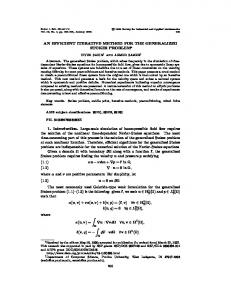
3.3 An Example We illustrate the idea behind the proposed algorithm using an example. The distributed WFG shown in Figure.1 spans 10 nodes labeled 1 to 10. All the nodes except 2, 6 and 10 are blocked initially. The unblocking conditions of each blocked node is as follows: f1=(2 ∧3)∨4, f3=(5∧6) ∨7, f4=8∧9, f5=1, f7=4, f8=7 and f9=(8∧10) ∨1. 4
©2010 International Journal of Computer Applications (0975 - 8887) Volume 1 – No. 19 7) When node 7 receives the CALL from 1, it sends REPORT(7, 8) to 1.Then it sends CALL(1,7,1/9) to 4
1
8) When node 8 receives the CALL from 4, it sends REPORT(8, 7) to 1 and it sends CALL(1,8,1/6) to 7. 2
9) When node 9 receives the CALL from 4, it sends REPORT(9, (8∧10) ∨1) to 1.Furthermore, it sends CALL(1,9,1/18) to 1,8 an 10 respectively.
4
3
10) When node 1 receives the CALL from 5, it updates weightinit
5
7
8
9
6
11) When node 4 receives the CALL from 7, it sends WEIGHT (4, 1/9) to 1. 12) When node 7 receives the CALL from 8, it sends WEIGHT(7,1/6) to 1.
10
13) When the initiator 1 receives the CALL from 9 through a back edge, it updates weightinit.
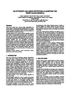
Figure 1. Wait-For Graph Let us consider node 1 initiates the algorithm and the messages are propagated in such a way to induce a Distributed Spanning Tree (DST) of WFG. In the Figure.2, the solid lines indicate the tree edge and dashed lines refers the non-tree edges. CALL Message REPORT Message
14) When node 8 receives the CALL from 9, it sends WEIGHT(8,1/18) to 1. 15) When node 10 receives the CALL from 9, it sends REPORT(10, φ) and WEIGHT(10,1/18) to 1 Whenever the initiator receives the REPORT from 2, 6 and 10, it simplifies the wait-for relations in the set UC. It finally declares nodes 1,3,4,5,7,8 and 9 are deadlocked.
3.4 Correctness Proofs The correctness of the proposed algorithm is proved by using the following four theorems.
1
Theorem 1: The algorithm terminates within a finite time. 2
4
3
5
7
6
8
9
10
Figure 2. The Message Flow 1) When node 1 initiates the algorithm, it sends CALL(1,1,1/3) to 2,3 and 4 respectively.
Proof of Sketch: By step 1, the initiator distributes the weight of one to its successors through CALL messages. When a blocked node receives the weight, it distributes the weight to its own successors by step II.2. Once a weight is distributed, it immediately reinitializes its weight into zero. If an active node receives the weight, it adds the weight with its own by step II.3 and II.4. Upon receiving CALL messages from all its predecessors, the leaves of distributed spanning tree are return the weight to the initiator directly through the WEIGHT message by step II.1 to II.4. The initiator adds the weight in WEIGHT message with weightinit by step IV. If the initiator receives the CALL through back edges, it updates the weightinit by step II.2.1 The messages are delivered within finite time and they are neither lost nor duplicated according to our system assumptions. The initiator stops the execution of the current instance once the sum of its weight (weightinit) upto one. Thus the theorem holds.
2) When node 2 receives the CALL from 1, it sends REPORT(2, φ) to 1. In addition, it sends WEIGHT(1,1/3) to 1
Theorem 2: The algorithm records the consistent snapshot of distributed Wait-For Graph.
3) When node 3 receives the CALL from 1, it sends REPORT (3, (5∧6) ∨7) to 1. In addition, it sends CALL(1,3,1/9) to 5, 6 and 7.
Proof of Sketch: Consider an edge (p,q) ∈ LWFGi. It is included in the LWFG only if a blocked process q sends a REPORT message to the initiator according to the step II.1. By step II, process q receives the CALL message from p iff q ∈ outp. And the process p has sent the REQUEST message to q earlier and it exists in inq. As a result, the edge (p,q) is included in the LWFGi only if both the processes p and q are blocked and a node q has received the CALL message from p. Therefore the snapshot is consistent and hence the theorem holds.
4) When node 4 receives the CALL from 1, it sends REPORT(4, 8∧9) to 1 and sends CALL(1.4,1/6) to 8 and 9 respectively. 5) When node 5 receives the CALL from 3, it sends REPORT(5, 1) to 1. It also sends CALL (1,5, 1/9) to 1. 6) When node 6 receives the CALL from 3, it sends REPORT(6, φ) to 1. Then it sends WEIGHT(6, 1/9) to 1.
5
©2010 International Journal of Computer Applications (0975 - 8887) Volume 1 – No. 19 Theorem 3: The algorithm detects a deadlock within a finite time. Proof of Sketch: Let us consider the contrary that the algorithm does not detect a deadlock D in the underlying system. Assume that there is a node i∈D where evaluate (fi) = true exists in the initiator. Since a node i is a member of deadlock D, it will be blocked forever. The evaluate(fi)=true implies that fi consists of only those nodes that are not deadlocked in the WFG. It contradicts our assumption i∈D. As a result, there exist a node j∈ Domain(fi) and whose state determines the state of i. Since evaluate (fi)=true, evaluate (fj) is also true. Similar to i, there is at least one node j’∈Domain(fJ) and whose state determines the state of j. By induction, there must exist a node n+1∈D such that n∈Domain(fn+1) and evaluate(fn)=true. Since active nodes have true unblocking conditions by step V, the algorithm does not evaluate(fi) as true during the simplification. So the algorithm does not report i∈D which contradicts our assumption. Thus, the algorithm reports deadlock iff it exists in the underlying system. Hence, the theorem is proved. Theorem 4 The algorithm does not report any false deadlock. Proof of Sketch: Let us consider the contrary that the algorithm declares a deadlock D although it does not exist in the underlying system. It implies that there are some edges recorded at the initiator but they do not exist in the WFG. Let us consider a edge (i,j) one among them. Since a node j sends REPLY to i, this edge is disappeared first in the WFG. If the edge (i,j) exists at the initiator, the node i executes either step I or II.1 of the algorithm. By step I, the initiator sends CALL message to its successor j. If it is executed the later step, a node i sends CALL message to each one of its successor including j. Let us assume that (i,j) is a tree edge of distributed spanning tree induced by the algorithm. When node j has received the CALL message from i, it records fj by executing the step II.1 or II.3. Furthermore, the unblocking condition is delivered to the initiator directly. Since the edge (i,j) is disappeared first from the WFG, fj is evaluated as true and the initiator does not record the edge(i,j) by step III. Since the edge (i,j) exists in D, node j must be deadlocked. If j executes step II.3 or II.4, it is included in the set A and the algorithm does not declare it as deadlocked. Let us now assume that (i,j) is a non treeedge of the spanning tree and disappeared first from the WFG. Therefore, j has sent a REPLY to i at some time, say t. If j receives the CALL message after t, the edge is not included at the initiator by step II.5. Similarly, when j receives the CALL message before t, it is included in the list of active nodes by step III. Hence, the edge (i,j) does not included in the initiator. Thus the theorem is proved.
3.5 Deadlock Resolution The algorithm selects a deadlocked node that unblocks more number of blocked nodes in the set UC as a victim of deadlock. The initiator is then sent the ABORT message directly to the victim. If a victim is insufficient to resolve a deadlock, the algorithm selects another node as a victim. This process continues until the unblocking conditions of remaining nodes in UC are satisfied.
complexities. The measurements are based on the assumption that the message transmission between any two nodes take one time unit. The initiator of the algorithm propagates the CALL messages along the edges of the WFG and receives exactly one REPORT message from each node. In addition, it receives one WEIGHT message from the leaves of induced distributed spanning tree. Hence, the total number of messages generated by the algorithm is less than e+2n where e is the number of edges and n is the number of nodes in the WFG. Since the REPORT messages are delivered to the initiator directly, its worst-case time complexity is d+1 where d is the diameter of the spanning tree induced by the algorithm. Since the proposed algorithm does not merge the unblocking conditions of several nodes, its worst-case data traffic complexity is O(1). The Table.1 compares the performance of the proposed algorithm with the previous algorithms. Table 1. Performance Comparison of Generalized Deadlock Detection and Resolution Algorithms Algorithms
Delay
Barcha-Toueg [4] Wang et.al [5]
4d
Number Message Of Length Messages 4e O(1)
Resolution no Scheme
3d+1
6e
O(1)
no Scheme
Kshemkalyani.e t.al [10] Kshemkalyani et.al [12] Brzezinski et.al [7] Chen et .al [8]
2d
O(1)
e messages
2d
4e2n+2l 2e
O(e)
1 message
4n
½ n2
O(n)
no Scheme
2d
2n
O(e)
3n messages
Soojung Lee [13] Soojung Lee [15] Soojung Lee [16] Our algorithm
n
e
O(d)
no Scheme
2d
2e
O(e+2n)
1 message
d+1