an efficient implementation of d-flip-flop using the gdi ... - CiteSeerX
Recommend Documents
Under this scenario, AES in CCM (Counter with CBC-MAC) mode has be- come one of the most ..... By consulting that table, we can compute. 02 Ã v efficiently.
DHT based Chord [7] [8], Pastry [9], Tapestry [10] & content based CAN [11]. ... networking theories and technologies, Liu suggested that a new computing ...
despite of the lawsuits about piracy to music and movies sharing providers [4]. P2P file sharing systems should at least implement three protocols: file-release ...
ITM University,. Gwalior, India. Shyam Babu Singh. Assistant Professor. ITM University,. Gwalior, India ..... 55), ISSN 2231-3133 ( Online). [17] Ravish Aradhya ...
multi-shift QR iteration of degree m carries out the steps. (A â µiI)= ... created to carry out this reduction. The kth .... Finally to carry out the transformation Pâ.
GDI - General Information. 13A-3. GENERAL INFORMATION. The Gasoline
Direct Injection System consists of sensors which detect the engine conditions,.
Mar 24, 2011 - An efficient mobile PACE implementation. Alex Wiesmaier,. Moritz Horsch. TU Darmstadt. HochschulstraÃe 10. 64289 Darmstadt, Germany.
energy efficient Optical Network Unit (ECONU) on an Altera. Stratix 4GT Field Programmable Gate Array (FPGA). An overview of the ECONU architecture along ...
the problem of efficiently building max tree structures from images and ... computer memory and flexible management of tree nodes together with a hash table to ...
software implementations of RSA algorithm are based on 2-prime. RSA. ... digital signatures and encryptions [2][3]. ... On the other hand, software solutions are.
that will become hardware into a synthesizable subset of a hard-. Permission to make digital/hard copy of all or part of this work for personal or classroom use is ...
ing of jobs and proposes a new tracking algorithm that can estimate states accurately ..... tion Strategies, Fourth USA/Europe Air Traffic Man- agement Research ...
A system of vector clocks is strongly consistent and it captures the happened before relations among events in the system. These clocks underlie solutions.
Carnegie Mellon University. Pittsburgh, PA 15213, USA [email protected]. ..... is also done by the Illinois Concert System compiler for two fine-grained object-oriented ...
digital signatures and encryptions [2][3]. Since RSA is based on ..... ADD, we use a temporary variable prevcar to store the carry produced in the outer loops.
To approximate scattered data points P, we formulate initial approximation function f as a uniform bicubic B- spline function, which is defined by a control lattice ...
(IJCSE) International Journal on Computer Science and Engineering. Vol. 02, No. ..... Bachelor of Technology degree in computer science and. Engineering ...
from the partially corrupted data produced by the decryption process. It intends to ... The results were analyzed based on 2500 iris images acquired from ...... [13] Rafael C. Gonzalez, Richard E. Woods, Steven L.Eddins, âDigital. Images ... [14] J
Today, companies need to ensure the quality of their software products by ... 10 and 49 employees) and medium-sized companies (between 50 and 249.
from the data plane and introduces network programmability for the development of net- work applications. .... 5.1 Violated Constraint Generation (VCG) Algorithm . .... ware Defined Networking (SDN) is a new networking paradigm that offers measurabil
development of applications in the context of open distributed environments. ... cols for interactions in a distributed application into classes, thus providing a.
AbstractâA transformerless single-stage single-switch AC/DC converter is presented in this paper. The converter allows a portion of the input power to be ...
Nov 25, 2013 - ... the right to the. 1. arXiv:1311.6244v1 [physics.comp-ph] 25 Nov 2013 ... convention, we also represent the arrays of 64-bit in- tegers from right ...
meandering micro striplines for magnetic particles switching ... two neighboring micro striplines to switch the magnetic ...... Biosens Bioelectron 22:1197â1204.
an efficient implementation of d-flip-flop using the gdi ... - CiteSeerX
A new implementation of efficient D-Flip-Flop (DFF) using. Gate-Diffusion-Input (GDI) technique is presented. This. DFF design allows reducing power-delay ...
➠
➡ AN EFFICIENT IMPLEMENTATION OF D-FLIP-FLOP USING THE GDI TECHNIQUE Arkadiy Morgenshtein¹, Alexander Fish² and Israel A. Wagner³ 1. Electrical Engineering Department, Technion, Haifa, Israel, e-mail: [email protected] 2. The VLSI Systems Center, Ben-Gurion University, Beer-Sheva, Israel, e-mail: [email protected] 3. IBM Research Laboratory, Haifa, Israel, e-mail: [email protected] simpler gates, lower transistor count, and lower power dissipation in many implementations, as compared with standard CMOS and PTL design techniques [6]. Multiple-input gates can be implemented by combining several GDI cells. The buffering constraints, due to possible VTH drop, are described in detail in [6], as well as technological compatibility with CMOS and SOI.
ABSTRACT A new implementation of efficient D-Flip-Flop (DFF) using
Gate-Diffusion-Input (GDI) technique is presented. This DFF design allows reducing power-delay product and area of the circuit, while maintaining low complexity of logic design. Performance comparison with other DFF design techniques is presented, with respect to gate area, number of devices, delay and power dissipation, showing advantages and drawbacks of GDI DFF, as compared to other methods. A variety of circuits have been implemented in 0.35µm and 0.18µm technologies to compare the proposed GDI structure with existing alternatives, showing an up-to 45% reduction in powerdelay product in GDI. Properties of implemented circuit are discussed and simulation results are reported. I.
INTRODUCTION
Wide
utilization of memory storage systems and sequential logic in modern electronics triggers a demand for high-performance and low-area implementations of basic memory components. One of the most important state-holding elements is the D-Flip-Flop (DFF) [1]. Various DFF circuits were researched and presented in the literature [1][3][4], aiming to achieve an optimal design in terms of delay, power and area. Some efficient techniques were developed and adopted by designers for a variety of technologies [1]. Gate-Diffusion-Input (GDI) design technique that was recently developed and presented in [6], proposes an efficient alternative for logic design in standard CMOS and SOI technologies. The GDI method is based on the simple cell shown in Fig. 1. A basic GDI cell contains four terminals - G (the common gate input of the nMOS and pMOS transistors), P (the outer diffusion node of the pMOS transistor), N (the outer diffusion node of the nMOS transistor) and the D node (the common diffusion of both transistors). P, N and D may be used as either input or output ports, depending on the circuit structure. Table 1 shows how various configuration changes of the inputs P, N and G in the basic GDI cell correspond to different Boolean functions at the output D. GDI enables
Table 1. Some logic functions that can be implemented with a single GDI cell
In this paper a new implementation of DFF using GDI technique is presented. This new DFF design allows reducing power-delay product and area of the circuit, while maintaining low complexity of logic design. GDI DFF is compared with other design techniques with respect to gate area, number of devices, delay and power dissipation, showing advantages and drawbacks of GDI implementation. The circuits have been implemented in 0.35µm and 0.18µm technologies and simulated to compare the proposed GDI structure with existing alternatives. Section II presents the structure of the GDI D-FlipFlop and its operational principle. In Section III the
II - 673
ISCAS 2004
➡
➡ alternative for obtaining the combination of low area and high performance.
alternative design methods are presented and compared with GDI. Conclusions and future work are discussed in Section IV. II.
GDI D-FLIP-FLOP IMPLEMENTATION AND OPTIMIZATION
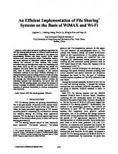
A novel implementation of a GDI DFF is shown in Fig. 2. It is based on the Master-Slave connection of two GDI D-Latches. Each latch consists of four basic GDI cells, resulting in a simple eight-transistor structure. The components of the circuit can be divided into two main categories: (a) Body gates – responsible for the state of the circuit. These gates are controlled by the Clk signal and create two alternative paths: one for transparent state of the latch (when the Clk is low and the signals are propagating through PMOS transistors), and another for the holding state of the latch (when the Clk is high and internal values are maintained due to conduction of the NMOS transistors). (b) Inverters (marked by ×) – responsible for maintaining the complementary values of the internal signals and the circuit outputs. An additional important role of inverters is buffering of the internal signals for swing restoration and improved driving abilities of the outputs. This partition to categories can be helpful for understanding of circuit operation and optimization. As can be seen, in body gates the transmission of the signal is performed through the diffusion nodes of the GDI cells. It might cause a swing drop of VTH in the output signals. This problem is solved by the internal inverters in their buffer role. Performance optimization of the proposed circuit can be performed by adjusting the transistor sizes (as sweep parameter in simulation) to obtain a minimal powerdelay product. This procedure is iterative and contains a sequence of separate size adjustments: (a) First, the same scaling factor is obtained for all transistors of the circuit (body gates and inverters). (b) Secondly, iterative size optimizations are applied separately to inverters and body gates (mostly by opposite shifting of the scaling factors around the “operation point” found in (a)), while targeting the minimal power-delay product. (c) For high load requirements, an additional optimization can be separately performed on the inverter of the Slave latch. The relatively compact structure of the proposed DFF, containing 18 transistors (with the inverter for complementary value of D), makes it an efficient
Fig. 2.
III.
GDI D-Flip-Flop implementation
SIMULATION RESULTS
In this work the proposed GDI DFF circuit has been implemented in 0.35µm and 0.18µm technology to compare the GDI design with a set of representative flipflops, commonly used for high performance design. Nine sets of comparisons were carried out on the test circuits. The circuits were simulated using Cadence SpectreS at 3.3V and 1.8V (for 0.35µm and 0.18µm technologies, respectively), 250 MHz and 27˚C, with load capacitance of 100fF. In our simulations the parasitic capacitances were taken into account. The simulation setup is shown in Fig. 3. The device under test was placed between input buffers to account for the current consumption from the previous stage, and output buffers to emulate real environmental conditions.
Fig. 3.
Simulation setup
The reference circuits are presented in Fig. 4. The set includes (a) modified C2MOS after [1], (b) PowerPC after [3], (c) HLFF after [4] and (d) DSTC after [1]. These circuits have been sized according to optimization procedure, as presented in [1].
II - 674
➡
➡
Fig. 4.
Set of representative flip-flops for comparison: (a) modified C2MOS, (b) PowerPC, (c) HLFF and (d) DSTC
Circuit
# of transistors
GDI DSTC PowerPC C2mos HLFF
18 12 20 24 20
Total Width [um] 33.1 56.8 59.5 64.9 105.4
CLK-Q (LH) [ps] 196.9 380.5 282.5 185.5 147.2
CLK-Q’ (HL) [ps] 272.1 208.5 390.4 463.1 193.4
CLK-Q (HL) [ps] 275.0 380.5 248.4 88.8 102.9
CLK-Q’ (LH) [ps] 203.2 177.3 332.5 343.9 210.7
CLK-Q (HL) [ps] 300.4 131.5 417.9 75.3 292.8
CLK-Q’ (LH) [ps] 313.3 361.1 259.5 341.3 128.3
Power [uw] 151.7 171.9 141.0 138.2 242.9
Max Delay [ps] 275.0 380.6 390.4 463.1 210.7
PDPtot [fJ] 41.7 65.4 55.0 64.0 51.2
Table 2. Simulation results for 0.18µm technology Circuit
# of transistors
GDI DSTC PowerPC C2mos HLFF
18 12 20 24 20
Total Width [um] 51.3 148.5 85.5 174.4 148.2
CLK-Q (LH) [ps] 313.3 125.1 428.3 222.2 292.7
CLK-Q’ (HL) [ps] 299.3 333.3 285.9 480.3 233.2
Power [uw] 812.7 1100.3 741.9 960.3 1050.4
Max Delay [ps] 313.3 361.0 428.2 480.3 292.8
PDPtot [fJ] 254.7 397.3 317.7 461.2 307.5
Table 3. Simulation results for 0.35µm technology Although, the number of transistors in DSTC circuit is less than in the GDI, the total gate area of GDI after optimization is smaller than in the alternative implementations. The improvement in performance and gate area in GDI is consistent in both fabrication technologies. It should be noted that the optimization in all compared circuits is performance-driven (minimal power-delay product is obtained by sizing), while
The comparative results are presented in Table 2 and Table 3 for 0.18µm and 0.35µm technologies, respectively. The best results in each compared category are emphasized. It can be seen, that GDI DFF outperforms the other circuits in terms of power-delay product and total gates area in both technologies (including the inverted inputs). The improvement in power-delay product in GDI is up to 37% in 0.18µm technology and up to 45% in 0.35µm technology.
II - 675
➡
➠ separate parameters, like average power and maximal delay are secondary. IV.
CONCLUSIONS AND FUTURE RESEARCH
A new implementation of high-performance D-FlipFlop using Gate-Diffusion-Input technique was presented. The proposed circuit has a simple structure, based on Master-Slave princple, and contains 18 transistors. An optimization procedure was developed for GDI DFF, based on iterative transistor sizing, while targeting a minimal power-delay product. Performance comparison with other DFF design techniques was shown, with respect to gate area, number of devices, delay and power dissipation. A variety of circuits have been implemented in 0.35µm and 0.18µm technologies to compare the proposed GDI structure with a set of representative flip-flops, commonly used for high performance design, showing an up-to 45% reduce in power-delay product and up to 71% reduction of gates area in GDI. The future research activities may include integration of the proposed DFF in complex digital systems, combining sequential and combinatorial logic. Hybrid design using both GDI and CMOS techniques should be researched for further optimization of various VLSI structures. The applicability of the GDI method for advanced fabrication technologies, like SOI and SOS, is currently under research. ACKNOWLEDGEMENTS The authors would like to thank G. Samuel and the staff of Technion Research Center of Microelectronic Systems, for their support during the research. We also thank O. Shirak, N. Ben-Shahar and other students for participating in projects in different stages of the research. REFERENCES [1]
J.M. Rabaey, A. Chandrakasan, B. Nikolic, “Digital Integrated Circuits”, 2nd edition, Prentice Hall, 2002.
[2]
V. Stojanovic and V.G. Oklobdzija, "Comparative Analysis of Master–Slave Latches and Flip-Flops for High-Performance and Low-Power Systems", IEEE J. Solid-State Circuits, vol. 34, no. 4, April 1999.
[3]
G. Gerosa, S. Gary, C. Dietz, P. Dac, K. Hoover, J. Alvarez, H. Sanchez, P. Ippolito, N. Tai, S. Litch, J. Eno, J. Golab, N. Vanderschaaf, and J. Kahle, “A 2.2 W, 80 MHz superscalar RISC microprocessor,” IEEE J. SolidState Circuits, vol. 29, pp. 1440–1452, December 1994.
II - 676
[4]
H. Partovi, R. Burd, U. Salim, F. Weber, L. DiGregorio, and D. Draper, “Flow-through latch and edge-triggered flip-flop hybrid elements,” ISSCC Dig. Tech. Papers, pp. 138–139, February 1996.
[5]
J. Yuan and C. Svensson, “New single-clock CMOS latches and flipflops with improved speed and power savings,” IEEE J. Solid-State Circuits, vol. 32, January 1997.
[6]
A. Morgenshtein, A. Fish, I.A. Wagner, “Gate-Diffusion Input (GDI) – A Power Efficient Method for Digital Combinatorial Circuits,” IEEE Trans. VLSI, vol. 10, no. 5, pp. 566-581, October 2002.