pulse width modulation (PWM) strategy for multilevel inverters are sine-triangle PWM ... sequence selection for the inverter voltage vectors. The identification of ...
International Journal of Computer Applications (0975 – 8887) Volume 23– No.2, June 2011
An Efficient Multilevel Inverter System for Reducing THD with Space Vector Modulation R.Karthikeyan
Dr.S.Chenthur Pandian
Assistant Professor / EEE, M.Kumarasamy college of Engineering, Karur, Tamil Nadu, India.
Principal, Dr.Mahalingam College of Engineering & Technology, Pollachi, Tamil Nadu, India.
ABSTRACT This paper proposes a generalized space vector pulse width modulation (SVPWM ) technique for hybrid multilevel inverters for minimizing total harmonic distortion (THD). The proposed method easily determines the actual location of the instantaneous reference space vector and the corresponding switching sequence of a multilevel inverter. The proposed algorithm offers a novel method for minimizing the total harmonic distortion (THD) of the output voltage of the inverter and uses simple arithmetic for determining the sector and does not require lookup tables. The proposed method can be extended to any n-level inverter, and a generalized algorithm is also proposed. Finally, the algorithm was implemented on a Digital Signal Processor (DSP) and the scheme is explained for a five level inverter, and experimental r esults are presented for a seven level inverter.
Several attempts have been made to develop algorithms by which switching vectors can be calculated by a microprocessor or a DSP. A generalized algorithm for n-level inverter is also presented. The paper is organized in six sections. Section II explains the proposed algorithm for hybrid multilevel inverter. Section III introduces the basic ideas for determining the switching vector in the proposed scheme. Section IV describes about improving voltage THD using proposed scheme. Section V shows the simulation and experimental results for a seven-level cascaded multilevel inverter. Section VI concludes the paper.
Key words –
Hybrid multilevel inverter, Space vector pulse width modulation (SVPWM ), Total harmonic distortion (THD).
1. INTRODUCTION M ultilevel inverter technology has emerged as a very important alternative in the field of medium and high- power industrial drive applications [1]. M odulation methods for hybrid multilevel inverter can be classified according to the switching frequencies methods. The most widely used techniques for implementing the pulse width modulation (PWM ) strategy for multilevel inverters are sine-triangle PWM (SPWM ) and space vector PWM (SVPWM ). The SVPWM is considered a better technique of PWM implementation as it has some advantage over SPWM in terms of good utilization of dc-bus voltage, reduced switching frequency and low current ripple. SVPWM presents the advantage of its extreme simplicity and its easy and direct hardware implementation in a digital signal processor (DSP). SVPWM can be efficiently executed in a few microseconds, achieving similar results compared with other PWM methods. The topology of a cascade multilevel inverter is shown in Fig. 1. In general, the SVPWM implementation involves the sector identification, determining the duration of each switching space vector voltage, determining the switching space vector and optimum switching sequence selection for the inverter voltage vectors. The identification of the sector can be done by coordinate transformation [9] or by repeated comparison of the three phase reference voltages [1]. In this paper, a novel SVPWM algorithm is proposed to reduce the THD and it uses simple arithmetic for determining the sector and does not require lookup tables. The switching vector is also directly determined using simple arithmetic and hence does not require lookup tables. This paper proposes a new approach to generate SVPWM signals for multilevel inverters and the generalized method uses sector identification at the two- levels.
Fig 1: Topology of multilevel inverter.
2. PROPOSED ALGORITHM
A new scheme for an n-level (n ≥3) cascaded multilevel hybrid inverter is proposed. In the proposed method, a simple algorithm of forming switching sequence is applied that leads to minimum change in voltage. An effective hybrid multilevel inverter must ensure that the total harmonic distortion (THD) in the voltage output waveform is small enough.This paper proposes a new algorithm for the hybrid multilevel inverter with unequal or varying voltage steps under the space vector modulation. The algorithm results in the minimal THD of output voltage of the cascaded multilevel inverter with unequal voltage steps. A new expression of THD is presented to simplify the derivation. Already we know some definitions and equations; the output voltage of the hybrid multilevel inverter is (2S+1) with the SVPWM modulation. Ep1, Ep2, Ep3 … Epn indicates the voltage steps in positive side and En1, En2, En3 … Enn indicates the voltage steps in negative steps. Θ1, Θ 2, Θ3 … Θ n are the switching angles that indicates the on and off instance of switches inside the inverter [2]-[3], [6].
11
International Journal of Computer Applications (0975 – 8887) Volume 23– No.2, June 2011 where,
2.1. Mathematical Formulation The algorithm can be expressed from the basis waveform by applying Fourier series analysis, the amplitude of any odd nth harmonic can be expressed as,
Vn
4 n
n k 1
Ek cos n
(1.0)
k
where n is an odd harmonic and Θ k is the k th switching angle. The amplitude of all even harmonics is zero. The modulation index m is defined as,
m
V1
(2.0)
n
4
E i 1 i
Vn
4 n
n 1,3,5,..
E1 cos n
(10.0)
1
M odulation index m for the basic output voltage
m
4
V1
4
n 1
E1 cos n
1
(11.0)
The THD is expressed as
d n 3,5,7,...
Vn2 V12
(12.0)
2.2. Structure of the Algorithm
Vn total harmonic component and V1 is the fundamental harmonic component. The voltage THD is defined as
THD n 3,5,7,...
Vn2 V12
(3.0)
Now, to find the problem and to implement an algorithm for the following variable inputs of the inverter V1, V2, V3 …, Vn. M odulation index term m. Output of the algorithm Θ1, Θ2, Θ 3 … Θn such that THD is minimum [9]. The inputs V1, V2, V3 …Vn come from dc capacitor voltages or the additions and subtractions of dc-capacitor voltages in the inverters. The dc-capacitor voltage is measured by using sensors. The input m is determined by a controller in multilevel inverter. The pulse angles Θ1, Θ2, Θ 3 … Θ n are used by the inverter to control the switches [10]. It is the important to note that minimizing voltage THD is desirable in some applications. In some high power applications one desires to limit each order harmonic to certain maximum allowed values. For the three phase system, the triple order harmonic can be cancelled without help from modulation techniques; yet it is desired to minimize THD for certain applications [10]. From modulation index m, determine the value of by
The control processing unit calculates the basic parameters to apply a switching state. The input data to the control processing unit is the reference space vector. During various iterations, the unit determines the sector number, triangle number of the subhexagon. The sector number and triangle number identifies the correct switching sequence. The flowchart is given for an n-level inverter and can be used for any n-levels without change. The input supply is the amplitude of the voltage steps and modulation index m, the initial value of ρo. The flow diagram of the proposed algorithm to find minimum THD is shown in Fig.2.
evaluating n
m
e 1
k 1 k
2
(4.0)
k
where,
ek
Ek
(5.0)
n
E i 1 l nk
E i 1 i k
n i 1
Ei
m mc
Ek / 2
(6.0)
En / 2
The switching angles are determined by, k
sin
(7.0)
k
The output voltages of the inverter is,
V
k 1
Ek V k V
k
V
k
V2
k
(8.0)
where V is unit function. By Fourier series expansion,
V
n 1,3,5,...
Fig 2: Flowchart of the Algorithm The modulation index m c is calculated for various iterations. The difference between two modulation index terms is calculated.
Vn sin n
(9.0)
(13.0)
where, δ – reference value to increases (or) decreases the pulse generation in the pulse generator. If the difference between two modulation index terms is less than reference value δ, the proposed algorithm outputs the optimal switching angles [9]. The iteration method is used to solve and to find minimization of the voltage THD.
3. PRINCIPLES OF THE PROPOSED SVPWM TECHNIQUE The SVPWM technique can be easily extended to all multilevel inverters [1]. This section explains the proposed technique for the generation of SVPWM for a five-level inverter. By using the 12
International Journal of Computer Applications (0975 – 8887) Volume 23– No.2, June 2011 space-vector diagram, the basic principles of the proposed SVPWM method can be easily explained. Fig.3 shows the space vector diagram of a five level inverter [1], [6]. The SVPWM implementation involves two phases: i) Selecting the switching vector and ii) Determining the Center of the subhexagon.
Fig 3: Space vector diagram for a five level inverter.
3.1. Selection of the Switching Vector In the proposed method, the small triangles formed by the adjacent voltage space vectors are called sectors. Such six sectors around a space vector forms a hexagon called subhexagon. The space vector modulation diagram of a multilevel inverter can be viewed composed of a number of subhexagons. Sector identification is done by determining the triangle that encloses the tip of the reference space vector. The shaded region in Fig. 4 shows two subhexagons. They are represented as “subhexagon I” having vector 000 as the centre and “subhexagon II” having the vector 032 as the centre. Another “subhexagon III” is also considered, having a vector 330 as the centre. The inner subhexagon can be viewed as a space vector diagram of a two-level inverter whose inverter voltage vectors switch between the lower most levels. Subhexagon II can be also viewed as a space vector diagram of a two level inverter whose; voltage vectors involve higher levels [1], [10]. The shifting of subhexagon in the space vector diagram of a multilevel inverter to the zero vector 000 simplifies the switching time calculations associated with multilevel inverters. The shifting of subhexagon II in the space vector diagram of a multilevel inverter toward the zero vector 000 involves the mapping of the sectors of subhexagon II to the sectors of the inner subhexagon. This is done by subtracting the vector at the centre of the subhexagon II from its other vector. In a reverse approach of mapping, the inner subhexagon can be mapped to subhexagon II by adding the voltage space vector at the centre of subhexagon II to the vector of the inner subhexagon. Consider the voltage vectors 000, 001, 101 and 111 associated with sector 5 of the inner subhexagon and the voltage space vector 032 which is the vector at the centre of subhexagon II. Adding the voltage space vector 032 to the voltage space vector associated with sector 5 of the inner subhexagon gives the vectors 032 (001+033), 022(101+022) and 421(100+021), which are the vectors associated with sector 5 of subhexagon.
Fig 4: M apping of reference space vector for switching vector generation. Also, the voltage space vector associated with any subhexagon can be generated by adding the vector at the centre of the particular subhexagon to the voltage space vector of the corresponding sectors in the inner subhexagon. In this paper, the mapping of the inner subhexagon to any other outer subhexagon called as reverse mapping is used to generate the vectors associated with any sector in the space vector diagram of the multilevel inverter.
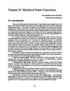
3.2. Determining the Centre of the subhexagon The space vector diagram of a five-level inverter, shown in Fig. 5 can be viewed as form of five levels with four layers. These levels are represented as Level 1 to 5. The instantaneous reference space vector lying in layer4 (P=4) and within the S1 region. Depending upon the layer of operation of the instantaneous reference space vector, all vectors for the center of the subhexagon are generated, and the vector which is closest to the reference space vector is taken as the center of the subhexagon. Fig. 5 also shows the six 60o regions S1, S2, S3, S4, S5, and S6. The subhexagon associated with the instantaneous reference space vector can be considered as centered on the inner side of layer 4.
Fig 5: Levels in the space vector diagram of a five-level inverter. The instantaneous reference space vector can be resolved in to the axes Vx, Vy and Vz using the following where Va, Vb and Vc are the instantaneous amplitude of the three reference phase voltages [1]
13
International Journal of Computer Applications (0975 – 8887) Volume 23– No.2, June 2011
Vx
3
Vy
3
Vz
3
2
Va Vc
2
Vb Va
2
Vc Vb
(14.0)
The axis lying in the 60◦ region which contains the instantaneous reference space vector will have maximum magnitude among the values.
4. MINIMIZING VOLTAGE THD WITH SVPWM TECHNIQUE In this section, a novel algorithm for reducing the total harmonic distortion (THD) of the inverter output voltage is described with space vector modulation. The proposed algorithm presented in this paper focus on getting minimal voltage THD. The SVPWM algorithm is used in a seven-level multilevel inverter with varying voltage steps. The algorithm in this paper is a generalized version used for any n-level. The measured voltage THD for multilevel inverter is minimum. The proposed scheme shows improvement of the voltage THD for multilevel inverter with unequal voltage steps. The algorithm shows no significant change in computational time and is efficiently implemented in a digital signal processor (DSP). The comparisons are carried out for the following two cases in a seven level inverter 1) E2 and E3 drop to 0.65 and 0.55 p.u. respectively and 2) E2 and E3 drop to 0.85 and 0.65 p.u. respectively, where E1 is 1p.u. in these cases. The voltage THD by the proposed algorithm is smaller particularly in the range of low modulation index. The THD improvement is also prominent because the voltage steps have large differences.
5. SIMULATION AND EXPERIMENTAL RESULTS 5.1.Simulation Results To verify the proposed schemes, a simulation model for a three phase seven level cascaded H-Bridge inverter is implemented as shown in Fig.6. The simulations were performed by using MATLAB SIM ULINK. It also helps to confirm the SVPWM switching strategy which then can be implemented in a DSP. The simulation parameters for constant switching frequency used for space vector pulse width modulation are 5kW rating, three phase load R = 100 ohms, L = 20 mH, each source Vdc = 5V, switching frequency 2 kHz. Phase leg voltages have been calculated and drawn for SVPWM M ethod shown in Fig.8.
Fig.6. Simulation diagram of three phase M ultilevel Inverter
Fig.7. Simulation result for fourteen -level inverter with SVPWM .
Fig.8.Space Vector Pulse Width M odulation Harmonic Spectrum
5.2. Experime ntal Results The proposed scheme is implemented using a TM S320C6701 DSP board to validate the theoretical analysis shown in Fig.11. The algorithm is tested on a experimental prototype of a seven-level cascaded inverter with unequal dc sources. The hardware parameters for space vector pulse width modulation are as follows, 0.5-kW rating, Single phase load R = 100 ohms, L = 20 mH, input sources contain Vd1, Vd2 & Vd3 are in 6V, 9V & 12V respectively, fundamental frequency is 50 Hz, switching frequency is 2 kHz and a TM S320C6701 – DSP controller. The Single phase output voltage waveform for SVPWM method shown in Fig.10. The switching patterns adopted are applied at the cascaded multilevel inverter switches to generate five or seven output voltage levels at proper modulation index. Fig.10 shows the output harmonics of Single phase multilevel inverter.
Fig.9. Output voltage of the multilevel inverter.
14
International Journal of Computer Applications (0975 – 8887) Volume 23– No.2, June 2011 at Annai M athammal Sheela Engineering College, Namakkal, India.
8. REFERENCES [1] J. Rodriguez, J.-S. Lai, and F. Z. Peng, 2002. “Multilevel inverters: A survey of topologies, controls, and applications,” IEEE Trans. Ind. Electron., vol. 49, no. 4, pp. 724–738.
Fig.10. Output harmonics of Single phase cascaded multilevel
[2] Y. Liang and C. O. Nwankpa, 1999. “A new type of STATCOM based on cascading voltage-source inverters with phase-shifted unipolar SPWM ,” IEEE Trans. Ind. Appl., vol. 35, no. 5, pp. 1118–1123. [3] S. Sirisukprasert, J.-S. Lai, and T.-H. Liu, 2002. “Optimum harmonic reduction with a wide range of modulation indexes for multilevel converters,” IEEE Trans. Ind. Electron., vol. 49, no. 4, pp. 875–881. [4] L. M . Tolbert, F. Z. Peng, and T. G. Habetler, 1999. “M ultilevel converters for large electric drives,” IEEE Trans. Ind. Appl., vol. 35, no. 1, pp. 36–44. [5] L. Li, D. Czarkowski, L. Yaguang, and P. Pillay, 2000. “M ultilevel selective harmonic elimination PWM technique in series-connected voltage inverters,” IEEE Trans. Ind. Appl., vol. 36, no. 1, pp. 160–170.
Fig.11. Hardware setup of Single phase cascaded multilevel
6. CONCLUSION This paper proposes a generalized SVPWM algorithm for multilevel inverters. A simple method for calculating switching angles time for hybrid multilevel inverters with unequal or varying voltage steps is used. The proposed algorithm uses simple arithmetic for sector identification and does not require lookup tables. The voltage THD is minimized with the new expression in the proposed algorithm. Thus the minimization of the voltage THD makes the proposed algorithm attractive in hybrid multilevel inverters with unequal or varying voltage steps. This leads to easier hardware implementation and the scheme shows no significant changes in computational time with the increase in level. The proposed SVPWM scheme is implemented on TM S320C6701-DSP platform. Experimental results are presented for seven-level inverter and the performance of the proposed algorithm is verified.
7. ACKNOWLEDGEMENTS
[6] K. Zhou and D. Wang, 2002 “Relationship between spacevector modulation and three-phase carrier-based PWM : A comprehensive analysis,” IEEE Trans. Ind. Electron., vol. 49, no. 1, pp. 186–196. [7] G. Carrara, S. G. Gardella, M . Archesoni, R. Salutari, and G. Sciutto, 1992. “A new multilevel PWM method: A theoretical analysis,” IEEE Trans. Power Electron., vol. 7, no. 3, pp. 497–505. [8] H. W. Van Der Broeck, H.-C. Skudenly, and G. V. Stanke, 1988. “Analysis and realization of a pulse width modulator based on voltage space vectors,” IEEE Trans. Ind. Appl., vol. 24, no. 1, pp. 142–150. [9] N. Celanovic and D. Boroyevich, 2001. “A fast space-vector modulation algorithm for multilevel three-phase converters,” IEEE Trans. Ind. Appl., vol. 37, no. 2, pp. 637–641. [10] P. F. Seixas, M . A. Severo M endes, P. Donoso Garcia, and A. M . N. Lima, 2000. “A space-vector PWM method for threelevel voltage source inverters,” in Proc. IEEE APEC, vol. 1, pp. 549–555.
This work was partially supported by Power Electronics Laboratory in Electrical and Electronics Engineering Department
15