Aerosol and Air Quality Research, 12: 145–160, 2012 Copyright © Taiwan Association for Aerosol Research ISSN: 1680-8584 print / 2071-1409 online doi: 10.4209/aaqr.2011.11.0187
An Efficient Multipollutant System for Measuring Real-World Emissions from Stationary and Mobile Sources Xiaoliang Wang*, John G. Watson, Judith C. Chow, Steven Gronstal, Steven D. Kohl Division of Atmospheric Sciences, Desert Research Institute, 2215 Raggio Parkway, Reno, NV 89512, U.S.A. ABSTRACT A portable dilution sampling and measurement system was developed for measuring multipollutant emissions from stationary and mobile sources under real-world operating conditions. This system draws a sample of exhaust gas from the source, dilutes it with filtered air and quantifies total volatile organic compounds (VOCs), carbon monoxide (CO), carbon dioxide (CO2), nitric oxide (NO), nitrogen dioxide (NO2), sulfur dioxide (SO2), oxygen (O2), particle size distribution, particle number and mass concentrations, and black carbon (BC) concentration at 1–6 sec interval. Integrated samples by canisters and filter packs are acquired for laboratory analyses of VOC speciation, particle mass concentration, light absorption, elements, isotopes, ions, ammonia (NH3), hydrogen sulfide (H2S), sulfur dioxide (SO2), carbon, and organic compounds. Experiments were carried out to evaluate this system. The accuracy of key real-time instruments were found to deviate < ± 12% from references. CO2 was used as the tracer gas to verify the concentration uniformity in the three measurement modules and relative concentration difference was < 5.1%. Instrument response time was tested by emissions from lighting and burning matches. The DustTrak DRX and optical particle counter (OPC) had the fastest response time, while other instruments had 3.5–21.5 sec delay from the DustTrak DRX and OPC. This system was applied to measure emissions from burning pine logs in a wood stove. The real-time data showed flaming, transition, and smoldering phases, and allowed real-time emission ratios to be calculated. Combing real-time data and laboratory analysis, this measurement system allows the development of multipollutant emission factors and source profiles. Keywords: PM2.5; Emission factor; Source profile; Biomass burning; Source characterization.
INTRODUCTION Real-world emissions represent effluents of multipollutant mixtures as they would appear soon after exiting the source, cooling, and equilibrating to ambient conditions (Cadle et al., 2009; Chow and Watson, 2011). Thousands of emission tests are made each year on stationary and mobile sources throughout the world for certification and compliance purposes, but these tests are of limited use for estimating real-world emission rates and chemical compositions (Chow and Watson, 2008). The most common approach to determine particulate matter (PM) emissions from stacks for compliance uses Method 5 (Elder et al., 1981; U.S.EPA, 1991) for total suspended particles (TSP) and Method 201A/202 for PM2.5 and PM10 (particles with aerodynamic diameters less than 2.5 µm and 10 µm, respectively) (U.S.EPA, 1996, 1997). Method 5 was adapted into two methods for testing
*
Corresponding author. Tel: 1-775-674-7177; Fax: 1-775-674-7009 E-mail address:
[email protected]
residential wood heaters (U.S.EPA, 2000a, b). Except for Method 5G, these methods use either a heated (120 ± 14°C) external glass-fiber filter or a filter installed inside the stack to collect PM at the effluent temperature. The heated samples are intended to minimize the collection of condensed water vapor. The high filter temperature precludes collection of several organic and inorganic compounds resulting in an underestimation of PM (England et al., 2000; Myers and Logan, 2002; England et al., 2007a, b). The flue gas is sent through a set of cold impingers containing solutions to capture condensable PM that penetrates the hot filter. However, these impingers also absorb gaseous sulfur dioxide (SO2) and volatile organic compounds (VOCs), thereby overestimating PM emissions (Corio and Sherwell, 2000). Neither the front glass-fiber filters nor the impinger catches are amenable to the types of chemical analyses that are commonly applied to ambient PM samples and that facilitate receptor-oriented source apportionment (Watson et al., 2008; Chakraborty and Gupta, 2010; Huang et al., 2010; Oh et al., 2011). Engine and vehicle certification tests are performed with an engine or chassis dynamometer (Code of Federal Regulations, 2001a, b, 2002), where the engine or vehicle operates on a prescribed transient cycle or at several steady-state loads.
146
Wang et al., Aerosol and Air Quality Research, 12: 145–160, 2012
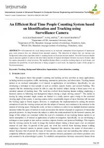
Emissions are sampled through a constant volume sampling (CVS) or partial-flow dilution (PFD) system (e.g., Chien et al., 2009; Wu et al., 2010). The test cycles are intended to represent real-world operating patterns, but real-world emissions are more variable (Sawyer et al., 2000; Yanowitz et al., 2000; Cocker et al., 2004). Despite their recognized limitations, a limited number of certification measurements are often the only ones available for constructing emission estimates (Chow, 2001; Lloyd and Cackette, 2001). To achieve a more realistic representation of actual PM emissions and chemical compositions from stationary sources, dilution sampling system are designed to simulate the diluting, cooling, and aging of the hot exhaust under similar conditions when the plume discharge to the atmosphere (Hildemann et al., 1989; Lipsky and Robinson, 2005; England et al., 2007a; Li et al., 2011). The American Society for Testing and Materials (ASTM; 2010) is developing a dilution sampling guidance for stationary source certification that better reconciles the current discrepancy between stationary or mobile source emissions and ambient PM measurements. The Emission Measurement Center of the U.S. EPA Office of Air Quality Planning and Standards (OAQPS) is also developing a Federal Reference Method (FRM) to better characterize source emissions of both filterable and condensable PM based on the dilution sampling method (Myers and Logan, 2002). The U.S. EPA Conditional Test Method (CTM) 039 uses dilution sampling method to measure PM2.5 and PM10 (U.S.EPA, 2004). Portable onboard emission measurement systems (PEMS) have been developed for in-use vehicle emission characterization of pollutants such as non-methane hydrocarbons (NMHC), carbon monoxide (CO), carbon dioxide (CO2), nitrogen oxides (NOx), and PM (Durbin et al., 2007; Abolhasani et al., 2008; Zhang and Frey, 2008; Johnson et al., 2009). Other species or parameters that are important to climate or health, such as black carbon (BC) and ultrafine particles, are typically not measured. Commercial PEMS are not designed to collect gas or filter samples that would enable measurement of speciated VOCs or PM source profiles needed for speciated emission inventories and source apportionment receptor models. A portable dilution source sampling and measurement system is described here that allows for direct measurements of real-world multipollutant emissions. This system harmonizes emission measurements for stationary (Watson et al., 2010; Wang et al., 2011) and mobile (Chow et al., 2010a) sources. Data from wood stove combustion, with a focus on continuous measurements throughout the burning cycle, are reported to illustrate how the system functions. MULTIPOLLUTANT DILUTION SAMPLING AND MEASUREMENT SYSTEM Fig. 1 illustrates the multipollutant dilution sampling and measurement system. A portion of the source effluent is drawn from a ducted or not-ducted plume, diluted and mixed with filtered air at near-ambient temperature, then directed to different monitors. Continuous monitors, described in Table 1, measure VOCs (aromatics), CO, CO2,
NO, NO2, SO2, O2, PM size distribution, PM number, PM mass, and PM BC at 1 to 6 sec intervals. Time-integrated samples are collected in parallel with canisters, absorbing substrates, and filters for later laboratory analysis of speciated VOCs, NH3, SO2, and H2S gases. Off-line PM analyses include mass, multiwavelength light absorption (babs), elements, isotopes, water-soluble ions, organic carbon (OC), elemental carbon (EC), and specific organic compounds including polycyclic aromatic hydrocarbons (PAHs) (Chow, 1995; Chow and Watson, 2012). This system is modularized and packaged into five modules (Figs. 2(a–e)) to provide for: 1) sample conditioning; 2) continuous gas monitoring; 3) integrated gas and particle sampling; 4) continuous PM monitoring; and 5) system power. Instruments are selected that operate on 12 V or 24 V so that batteries or power supplies (when line power is available) can be easily procured at or near the measurement location. The modular nature of the system allows for quick replacement of the monitors as newer and more sensitive technology becomes available. A Method 5 buttonhook nozzle and probe is used to extract effluent from a duct and drawn to the sample conditioning module (Fig. 2(a)) through a heated (to ~5°C above the sample temperature) or insulated tube to minimize vapor condensation and thermophoretic particle losses. The sample is rapidly diluted with clean air generated by a compressor (Model 107CDC20, Thomas Pump & Machinery, Sheboygan, WI) and filtered by activated carbon and a high efficiency particulate air (HEPA) filter. An elutriator (Fig. 2(f)) enhances mixing between the sample and dilution flows (England et al., 2007a, b) by introducing the undiluted sample flow through a center tube surrounded by 96 1.6 mm holes through which the dilution air is directed. The diluted sample passes into a 1.5 liter (L) residence chamber where gases and particles can equilibrate to reach a stable particle size distribution (Chang et al., 2004). The aging time at the flow rate of 28.7 L/min in Fig. 1 is ~3 sec, similar to the system described by Lipsky and Robinson (2005) who estimated that the equilibrium time is < 2 sec when the total particle surface area is greater than 0.01 m2/m3. A larger-volume residence chamber can be substituted when longer residence times or higher flow rates are deemed necessary. The sample stream then passes through a cyclone (Model URG-2000-30ENG, URG Corporation, Chapel Hill, NC) to remove particles larger than ~7 µm at the specified flow rates. Three separate flow streams are drawn into the continuous and integrated sample modules (i.e., Figs. 2(b–d)) for quantification using inert Teflon tubing and a Teflon-membrane filter for the gas monitors and conductive silicone tubing for the PM monitors. Three nondispersive infrared (NDIR) CO2 analyzers measure CO2 concentrations in the undiluted exhaust, diluted sample, and dilution flow (background) every 1.5 sec. The instantaneous dilution ratio (DR) is calculated as (Ning and Sioutas, 2010): DR
[CO 2 ]undiluted [CO 2 ]background [CO 2 ]diluted [CO 2 ]background
.
(1)
Wang et al., Aerosol and Air Quality Research, 12: 145–160, 2012
147
Fig. 1. Schematic diagram of the multipollutant dilution sampling and measurement system. The listed flow rates are for operation with a dilution ratio of 40. The dilution ratio can be adjusted by changing the dilution and make-up flows. The one-liter canister flow rate is controlled by a critical orifice. CO, CO2, and methane (CH4) are analyzed by gas chromatograph with flame ionization detector (GC-FID), and NMHC (C2–C11) are analyzed by GC-mass spectrometry (MS)-FID (U.S.EPA, 1999). Since different filter media are needed for comprehensive chemical speciation (Chow et al., 2008; Watson and Chow, 2011), four filter packs are sampled in parallel (Chow and Watson, 2012), with a typical configuration shown in Fig. 1. Each filter pack is preceded by a PM2.5 impactor (Model 202-100, Airmetrics, Eugene, OR). The flow rate (5 L/min) through each filter pack is controlled by a feedback loop between the pump (Model B2736, BGI Inc., Waltham, MA) speed and flow meter (Model 41221, TSI Inc.) readings. Additional sampling media, such as a 2,4-Dinitrophenylhydrazine (DNPH) cartridge for carbonyls (Fung and Grosjean, 1981), a Tenax cartridge for heavy hydrocarbons (Zielinska et al., 1986;
1994b; Zielinska and Fujita, 1994a), or filter media for additional PM speciation can be added to this module. The continuous PM monitoring module (Fig. 2(d)) contains a DustTrak DRX aerosol monitor, which is a combination of nephelometer and optical particle counter (OPC) and simultaneously measures PM1, PM2.5, PM4, PM10 and PM15 mass concentrations (Wang et al., 2009). The condensation particle counter (CPC) measures the total number concentration of particles larger than 10 nm. Since the maximum concentration that the CPC can measure without coincidence losses is ~100,000 particle/cm3, a dilution bridge similar to the leaky filter method (Whitby et al., 1972) is added upstream to enable the measurement of high concentrations; the dilution ratio is measured before and after each test. The OPC measures particle size distributions in the optical diameter range of 0.3–25 µm in 15 channels based on single particle light scattering. The
148
Wang et al., Aerosol and Air Quality Research, 12: 145–160, 2012
Table 1. Description of continuous monitors. Monitoring System CO2 analyzers; Model SBA-4 (PP Systems, Amesbury, MA) Emission Analyzer; Model 350 S (Testo Inc., Sparta, NJ)
Photoionization detector (PID); Model 102+ (PID Analyzers LLC, Pembroke, MA) Condensation Particle Counter; Model 3007 ( TSI Inc., Shoreview, MN) Micro-aethalometer; Model AE51 (Magee Scientific, Berkeley, CA) DustTrak DRX; Model 8534 (TSI Inc., Shoreview, MN) Optical Particle Counter; Model 1.108 (Grimm Aerosol Technik GmbH & Co., KG, Ainring, Germany)
Observables
Undiluted CO2 Diluted CO2 Background CO
Measurement Range
0–100,000 ppm 0–5,000 ppm 0–5,000 ppm 0–500 ppm
CO2
0–50% vol.
NO
0–3,000 ppm
NO2
0–500 ppm
SO2
0–5,000 ppm
O2 Total aromatic VOCs (isobutylene equivalent) PM number concentration
0–25% vol. 0.1–3000 ppm Size: >10 nm Number: 0–100,000 cm-3
Data Nominal Rate Precision/Accuracy 1.5 CO2: < 1% of span sec concentration 1 sec CO: < 2 ppm (0–39.9 ppm) < 5% of measured value (mv; ≥ 40 ppm) CO2: ± 0.3% vol. + 1% of mv (0–25% vol.) ± 0.5% vol. + 1.5% of mv (> 25% vol.) NO: < 2 ppm (0–39.9 ppm) < 5% of mv (40–300 ppm) NO2: < 5 ppm (0–99 ppm) < 5% of mv (> 99 ppm) SO2: < 5 ppm (0–99 ppm) < 5% of mv (100– 2,000 ppm) < 10% of mv (2,001– 5,000 ppm) O2: ~0.9 for flaming phase and MCE < ~0.85 for smoldering phase (e.g., Koppmann et al., 2005; Reid et al., 2005b). The variety of continuous measurements offers the possibility of greater precision in distinguishing among the different wood combustion phases. In the flaming phase, CO2 and particle concentrations were relatively stable, while total VOCs, CO, and NO increased. The MCE decreased to ~0.9 during this period, indicating the combustion became less efficient
when volatile fuel components near the wood surface were burned (Chen et al., 2007). Because the stove was cold at the initiation of the experiment and the pinewood pieces were too large for complete combustion, the fire entered a transition from flaming to smoldering after ~15 minutes. During this transition period, the CO2 concentration declined, while CO and NO levels increased, resulting in declining MCE. Total VOCs, particle number, BC, and PM2.5 mass concentrations were relatively stable during this period. Average total VOCs in this phase were 22% higher than during the flaming phase, BC was 9% lower, while particle number and PM2.5 differed by < 8%. Around 12:45:05, the fire entered the smoldering phase, and all pollutant concentrations decreased when the MCE reached a minimum of ~0.80. A gradual increase of MCE from the second half of the smoldering phase has been observed in earlier studies (Hays et al., 2005; Chen et al., 2007; Hosseini et al., 2010) and is probably due to the decrease of CO concentrations as the smoldering temperature decreases toward the end of the burn. The BC/PM2.5 from the microaethalometer and DustTrak DRX decreased continuously from the beginning of the transition phase, indicating a decrease in the fraction of PM that absorbs light at 880 nm. This is consistent with earlier observations that soot particles are mostly formed in the flaming phase due to insufficient O2 in poorly mixed areas while in the smoldering phase particles are largely formed by volatile organics condensation (Reid et al., 2005a). Table 5 shows correlations among concentrations during the wood burning test with selected parameters plotted in Fig. 6. The highest squared correlations (r2 = 0.96) was observed between the number concentration and PM2.5 mass concentration by the OPC, which is expected since the OPC PM2.5 mass concentrations was calculated from number concentration. The PM2.5 mass concentrations by the OPC and DustTrak DRX were also well correlated (r2 = 0.78); both instruments are based on light scattering principle. However, as shown in Fig. 6(a), the linear regression slope was only 0.03, indicating the OPC readings were ~30 times lower than the DustTrak DRX. This difference is partially
154
Wang et al., Aerosol and Air Quality Research, 12: 145–160, 2012
because the OPC PM2.5 concentration was calculated from particle number concentrations by assuming that particles
were spheres with unit density, while the DustTrak DRX derived PM2.5 concentrations from photometric signal
Fig. 5. Time series of instrument responses to wood stove emission: a) total VOCs; b) CO; c) undiluted CO2; d) diluted CO2; e) background CO2; f) modified combustion efficiency (MCE); g) NO; h) O2; i) particle number by CPC and OPC; j) black carbon; k) PM2.5 mass by the DustTrak DRX and OPC; and l) ratio of BC to PM2.5 (by DustTrak DRX). Response time differences among instruments were corrected by aligning the sharp rising concentrations when the fire was ignited. Gas and particle concentrations except CO2 were corrected for dilution. SO2 and NO2 were near detection limits and are not plotted. Vertical dash lines separate different burning phases, and the arrows on the panel k point to the center time of the particle size distribution scan shown in Fig. 7.
Wang et al., Aerosol and Air Quality Research, 12: 145–160, 2012
155
Table 4. Average pollutant concentrations and ratios to CO2 for each pinewood burning phase. Parameter Flaming Transition VOC (ppm) 121 147 CO (ppm) 202 346 CO2 (ppm) 3353 2895 NO (ppm) 5.59 9.15 PM Number (cm-3) Burning Phase Average 8.52E+06 9.19E+06 BC (mg/m3) 3.42 3.10 PM2.5 by DRX (mg/m3) 109 107 MCE (-)a 0.95 0.90 BC/PM2.5 (-) 3.95% 3.15% ∆VOC/∆CO2 (%) 4.07% 6.06% ∆CO/∆CO2 (%) 7.30% 15.04% ΔNO/ΔCO2 (%) 0.20% 0.40% Emission Ratio ΔCPC/ΔCO2 (#/cm3/ppm) 3.00E+03 3.92E+03 ΔBC/ΔCO2 (mg/m3/ppm) 1.24E-03 1.28E-03 ΔPM2.5/ΔCO2(mg/m3/ppm) 4.01E-02 4.64E-02 a MCE: modified combustion efficiency defined as MCE = [CO2]/([CO2] + [CO])
Smoldering 119 264 1385 8.85 4.41E+06 0.83 47 0.86 1.13% 14.26% 29.10% 1.09% 4.74E+03 6.46E-04 4.07E-02
Overall 128 265 2546 7.73 7.30E+06 2.44 87 0.90 2.75% 8.14% 17.01% 0.56% 3.86E+03 1.05E-03 4.21E-02
Table 5. Squared correlation (r2) between emission species during flaming, transition, and smoldering phases (r2 ≥ 0.5 are in bold type). CPC Number OPC Number BC Concentration Concentration -
DustTrak PM2.5 mass
Parameter
VOC
CO
CO2
VOC CO CO2 CO2/(CO2 + CO) NO CPC Number Concentration OPC Number Concentration BC DustTrak PM2.5 mass OPC PM2.5 mass
0.79 0.03 0.14 0.42
0.01 0.42 0.62
0.60 0.17
CO2/ (CO2 + CO) 0.64
0.34
0.14
0.61
0.17
0.00
-
-
-
-
0.53
0.36
0.32
0.15
0.02
0.59
-
-
-
0.26 0.46 0.56
0.09 0.30 0.42
0.59 0.17 0.20
0.16 0.14 0.00
0.11 0.01 0.04
0.50 0.31 0.49
0.68 0.73 0.96
0.53 0.57
0.78
based on Arizona Road Dust calibrations (Wang et al., 2009). Furthermore, the OPC experienced coincidence losses for concentrations above ~6 mg/m3 as indicated by the decreasing slope in Fig. 6(a) at higher concentrations. The OPC also has a lower size cut-off at ~0.3 µm, and many particles were at or below this size range. The mass concentration measured by the Teflon-membrane filter (Fig. 2(c)) can be used to adjust mass concentrations by the DustTrak DRX and OPC. Fig. 6(b) shows r2 = 0.79 for total VOCs and CO, both formed from incomplete combustion due to low combustion temperatures, an insufficient air supply, or poor mixing of fuel and air. On the other hand, BC, another product of incomplete combustion, was poorly correlated with CO (r2 = 0.09). As shown in Figs. 5 and 6(c), in the flaming and smoldering phase, BC and CO had fair correlations but with different slopes and intercepts, probably due to different formation mechanisms. In the flaming phase, both BC and CO form in a fuel-rich flame, while in the smoldering phase, BC and CO form due to low fire temperatures. In the transition phase, they were uncorrelated when CO continued
NO -
-
to increase while BC was relatively stable. BC was better correlated with CO2 (r2 = 0.59) than with CO. The continuous emission measurement permits calculation of emission ratios (ER) for different burning phases as listed in Table 4. The emission ratio is defined as (Andreae et al., 1998; Koppmann et al., 2005): ER
[X]plume [X]background ΔX ΔCO 2 [CO 2 ]plume [CO 2 ]background
(3)
where [X]plume and [X]background are the measured concentrations in the plume and background, respectively. Except for PM2.5, ERs varied for different burning phases. This observation underlines the importance of using continuous data for estimating ERs, especially when X is poorly correlated with CO2 (Andreae, 2001). Fig. 7 shows examples of particle number distributions from SMPS and OPC measurements from each stage of the experiment. Although particle number concentrations varied over the 135 sec SMPS scan time, these more detailed size
156
Wang et al., Aerosol and Air Quality Research, 12: 145–160, 2012
a)
b)
c) Fig. 6. Correlations between diluted pollutants during flaming, transition, and smoldering phases for: a) OPC PM2.5 vs. DustTrak PM2.5; b) total VOC vs. CO; and c) BC vs. CO.
Fig. 7. Snapshots of particle size distribution during different stages of the wood burning experiment. Time stamp corresponds to the two-minute scan period of the scanning mobility particle sizer (SMPS). The centers of scans are labeled as arrows in Fig. 5(k). distributions provide useful information on particle evolution over the burn period. Consistent with Figs. 5(i–k), the ambient background concentration was orders of
magnitude lower than the plume levels. At the early stage of ignition, particle sizes peaked ~0.026 µm, smaller than during later burning phases. Since particle concentrations
Wang et al., Aerosol and Air Quality Research, 12: 145–160, 2012
were relatively low at this phase and there were not many large particles in the plume, these particles had lower coagulation efficiencies and were not quickly scavenged. The count median diameter (CMD) in the ignition phase was 0.02–0.04 µm. In the flaming phase, particles were larger (CMD = 0.04–0.06 µm) and concentrations were higher with particles present in both nuclei (~0.005–0.1 µm) and accumulation (~0.1–2.5 µm) modes. In the transition phase, particles in the nuclei mode decreased and more particles appear in the accumulation mode, with CMD of 0.06–0.09 µm. The shape of the size distribution in the smoldering phase was similar to that in the transition mode (CMD = 0.05–0.09 µm), but with lower concentrations. This observation of size distribution change from flaming to smoldering phase is similar to that observed during wheat straw combustion (Hays et al., 2005). Maruf Hossain and Park (2011) observed a decrease of mode diameter from ~0.18 µm to ~0.09 µm from flaming to smoldering combustion of rice straw. They controlled the combustion so that only flaming or smoldering predominated, which differs from the natural transition from flaming to smoldering in this study. Particle sizes observed in this experiment are in the same range as a recent study using fast scan mobility analyzers (1 sec time resolution), but are somewhat smaller than most studies summarized by Reid et al. (2005b). Differences in fuel and combustion conditions contribute to these discrepancies. CONCLUSIONS A portable dilution sampling and measurement system was developed to measure multipollutant emissions from stationary and mobile sources. In addition to the criteria pollutants (i.e., CO, NOx, SO2, and PM), additional pollutants (e.g., total VOCs, CO2, BC, ultrafine particle number concentration, and particle size distributions) are measured continuously. Integrated canister and filter samples allow thorough analysis of VOC speciation and PM chemical compositions. This system enables measurement of continuous emission characteristics and development of multipollutant emission factors and source profiles under real-world conditions. Key component continuous instruments were evaluated in the laboratory for their accuracy. Instruments responses agree with reference concentrations with ± 12% deviation and excellent correlation (r2 > 0.995). The uniformity of species concentrations delivered to the three measurement modules was evaluated using CO2 as the tracer gas. The relative error was found to be < 5.1% indicating uniform mixing. Differences in time responses of individual detectors were evaluated by measuring emissions from lighting and burning matches. It was found that the DustTrak DRX and OPC had the fastest responses to aerosol concentration changes, while other instruments showed 3.5–21.5 sec delay. This system was tested for measuring emissions from burning pinewood logs in a wood stove. Three burning phases: flaming, transition, and smoldering were observed from the emission time series. A reasonable squared correlation (r2 = 0.78) was found between the PM2.5 mass
157
concentrations measured by the DustTrak DRX and OPC. However, the DustTrak concentration was ~30 times higher than the OPC, underlining the necessity of calibrating mass concentrations by optical instruments with gravimetric methods. Good correlation was also found between VOCs and CO (r2 = 0.79) during the entire burn. Correlations between species and the modified combustion efficiency were generally poor. Continuous emission data allows evaluation of emission ratios in different burning phases, which will lead to more accurate estimation of emission inventories. Size distribution measurement of wood combustion showed that most particles are smaller than 0.2 µm, with count median diameter (CMD) 0.02–0.04 in ignition phase, 0.04–0.06 µm in flaming phase, 0.06–0.09 µm in transition phase, and 0.05–0.09 in smoldering phase. ACKNOWLEDGEMENTS Development of the dilution sampling and measurement system was partially sponsored by the Wood Buffalo Environmental Association (WBEA) of Alberta, Canada (Contact 010109-123109), the U.S. Department of Defense Strategic Environmental Research and Development Program (Contract WP-1336), and the U.S. Environmental Protection Agency Small Business Innovation Research (Grant EP-D-06-071). The authors are grateful to LungWen Chen of DRI, Tom Baldwin and Don House of Baldwin Environmental Inc., Tom Merrifield of BGI Inc., Sergio Dávila Riquelme of Catholic University of Temuco, and Yusuke Kuromiya of Kanazawa University for assistances in the wood stove emission test. We also thank TSI Inc. for providing the DustTrak DRX for testing. REFERENCES Abolhasani, S., Frey, H.C., Kim, K., Rasdorf, W., Lewis, P. and Pang, S.H. (2008). Real-World in-Use Activity, Fuel Use, and Emissions for Nonroad Construction Vehicles: A Case Study for Excavators. J. Air Waste Manage. Assoc. 58: 1033–1046. Andreae, M.O. (2001). Emission of Trace Gases and Aerosols From Biomass Burning. Global Biogeochem. Cycles 15: 955–966. Andreae, M.O., Andreae, T.W., Annegarn, H.J., Beer, J., Cachier, H., Le Canut, P., Elbert, W., Maenhaut, W., Salma, I., Wienhold, F.G. and Zenker, T. (1998). Airborne Studies of Aerosol Emissions From Savanna Fires in Southern Africa: 2. Aerosol Chemical Composition. J. Geophys. Res. 103: 32119–32128. ASTM International (2010). Standard Guideline for Determining PM2.5 and PM10 Mass in Stack Gases: D2203-WK8124_Guideline. Cadle, S.H., Ayala, A., Black, K.N., Graze, R.R., Koupal, J., Minassian, F., Murray, H.B., Natarajan, M., Tennant, C.J. and Lawson, D.R. (2009). Real-World Vehicle Emissions: A Summary of the 18th Coordinating Research Council on-Road Vehicle Emissions Workshop. J. Air Waste Manage. Assoc. 59: 130–138. Calvo, A.I., Castro, A., Pont, V., Cuetos, M.J., Sánchez,
158
Wang et al., Aerosol and Air Quality Research, 12: 145–160, 2012
M.E. and Fraile, R. (2011). Aerosol Size Distribution and Gaseous Products from the Oven-Controlled Combustion of Straw Materials. Aerosol Air Qual. Res. 11: 616–629. Chakraborty, A. and Gupta, T. (2010). Chemical Characterization and Source Apportionment of Submicron (PM1) Aerosol in Kanpur Region, India. Aerosol Air Qual. Res. 10: 433–445. Chang, M.C.O., Chow, J.C., Watson, J.G., Hopke, P.K., Yi, S.M. and England, G.C. (2004). Measurement of Ultrafine Particle Size Distributions from Coal-, Oil-, and GasFired Stationary Combustion Sources. J. Air Waste Manage. Assoc. 54: 1494–1505. Chen, L.W.A., Moosmüller, H., Arnott, W.P., Chow, J.C., Watson, J.G., Susott, R.A., Babbitt, R.E., Wold, C.E., Lincoln, E.N. and Hao, W.M. (2007). Emissions from Laboratory Combustion of Wildland Fuels: Emission Factors and Source Profiles. Environ. Sci. Technol. 41: 4317–4325. Chien, S.M., Huang, Y.J., Chuang, S.C. and Yang, H.H. (2009). Effects of Biodiesel Blending on Particulate and Polycyclic Aromatic Hydrocarbon Emissions in Nano/ Ultrafine/Fine/Coarse Ranges from Diesel Engine. Aerosol Air Qual. Res. 9: 18–31. Chow, J.C. (1995). Critical Review: Measurement Methods to Determine Compliance With Ambient Air Quality Standards for Suspended Particles. J. Air Waste Manage. Assoc. 45: 320–382. Chow, J.C. (2001). 2001 Critical Review Discussion Diesel Engines: Environmental Impact and Control. J. Air Waste Manage. Assoc. 51: 1258–1270. Chow, J.C. and Watson, J.G. (2008). New Directions: Beyond Compliance Air Quality Measurements. Atmos. Environ. 42: 5166–5168. Chow, J.C. and Watson, J.G. (2011). Air Quality Management of Multiple Pollutants and Multiple Effects. Air Qual. Clim. Change 45: 26–32. Chow, J.C. and Watson, J.G. (2012). Aerosol Chemical Analysis on Filters, In Aerosols Handbook: Measurement, Dosimetry, and Health Effects, Ruzer, L. and Harley, N.H. (Eds.), CRC Press/Taylor & Francis, New York, NY. Chow, J.C., Doraiswamy, P., Watson, J.G., Chen, L.W.A., Ho, S.S.H. and Sodeman, D.A. (2008). Advances in Integrated and Continuous Measurements for Particle Mass and Chemical Composition. J. Air Waste Manage. Assoc. 58: 141–163. Chow, J.C., Wang, X.L., Kohl, S.D., Gronstal, S. and Watson, J.G. (2010a). Heavy-duty Diesel Emissions in the Athabasca Oil Sands Region, In Proc. 103rd Annual Meeting of the Air & Waste Management Association, Tropp, R.J. and Legge, A.H. (Eds.), Air & Waste Management Association, Pittsburgh, PA. Chow, J.C., Watson, J.G., Chen, L.W.A., Chang, M.C.O., Robinson, N.F., Trimble, D.L. and Kohl, S.D. (2007). The IMPROVE_A Temperature Protocol for Thermal/ Optical Carbon Analysis: Maintaining Consistency With a Long-Term Database. J. Air Waste Manage. Assoc. 57: 1014–1023. Chow, J.C., Watson, J.G., Green, M.C. and Frank, N.H. (2010b). Filter Light Attenuation as a Surrogate for
Elemental Carbon. J. Air Waste Manage. Assoc. 60: 1365–1375. Chow, J.C., Watson, J.G., Pritchett, L.C., Pierson, W.R., Frazier, C.A. and Purcell, R.G. (1993). The DRI Thermal/ Optical Reflectance Carbon Analysis System: Description, Evaluation and Applications in U.S. Air Quality Studies. Atmos. Environ. 27A: 1185–1201. Chow, J.C., Watson, J.G., Robles, J., Wang, X.L., Chen, L.W.A., Trimble, D.L., Kohl, S.D., Tropp, R.J. and Fung, K.K. (2011). Quality Assurance and Quality Control for Thermal/Optical Analysis of Aerosol Samples for Organic and Elemental Carbon. Anal. Bioanal. Chem. 401: 3141– 3152. Cocker, D.R., Shah, S.D., Johnson, K., Miller, J.W. and Norbeck, J.M. (2004). Development and Application of a Mobile Laboratory for Measuring Emissions from Diesel Engines 1. Regulated Gaseous Emissions. Environ. Sci. Technol. 38: 2182–2189. Code of Federal Regulations (2001a). 40 CFR Part 86, Control of Emissions from New and in-use Highway Vehicles and Engines, Prepared by U.S. Government Printing Office, Washington, DC. Code of Federal Regulations (2001b). 40 CFR Part 89, Control of Emissions from New and in-use Nonroad Compression-ignition Engines, Prepared by U.S. Government Printing Office, Washington, DC. Code of Federal Regulations (2002). 40 CFR Part 1065, Engine Testing Procedures, Prepared by U.S. Government Printing Office, Washington, DC. Corio, L.A. and Sherwell, J. (2000). In-Stack Condensible Particulate Matter Measurements and Issues. J. Air Waste Manage. Assoc. 50: 207–218. Durbin, T.D., Johnson, K., Cocker, D.R., Miller, J.W., Maldonado, H., Shah, A., Ensfield, C., Weaver, C., Akard, M., Harvey, N., Symon, J., Lanni, T., Bachalo, W.D., Payne, G., Smallwood, G. and Linke, M. (2007). Evaluation and Comparison of Portable Emissions Measurement Systems and Federal Reference Methods for Emissions from a Back-Up Generator and a Diesel Truck Operated on a Chassis Dynamometer. Environ. Sci. Technol. 41: 6199–6204. Elder, J.C., Tillery, M.I. and Ettinger, H.J. (1981). Evaluation of EPA Method 5 Probe Deposition and Filter Media Efficiency. J. Air Pollut. Contr. Assoc. 31: 66–67. England, G.C., Watson, J.G., Chow, J.C., Zielinska, B., Chang, M.C.O., Loos, K.R. and Hidy, G.M. (2007a). DilutionBased Emissions Sampling from Stationary Sources: Part 1. Compact Sampler, Methodology and Performance. J. Air Waste Manage. Assoc. 57: 65–78. England, G.C., Watson, J.G., Chow, J.C., Zielinska, B., Chang, M.C.O., Loos, K.R. and Hidy, G.M. (2007b). Dilution-Based Emissions Sampling from Stationary Sources: Part 2. Gas-Fired Combustors Compared With Other Fuel-Fired Systems. J. Air Waste Manage. Assoc. 57: 79–93. England, G.C., Zielinska, B., Loos, K., Crane, I. and Ritter, K. (2000). Characterizing PM2.5 Emission Profiles for Stationary Sources: Comparison of Traditional and Dilution Sampling Techniques. Fuel Process. Technol.
Wang et al., Aerosol and Air Quality Research, 12: 145–160, 2012
65: 177–188. Fung, K.K. and Grosjean, D. (1981). Determination of Nanogram Amounts of Carbonyls As 2,4Dinitrophenylhydrazones by High-Performance Liquid Chromatography. Anal. Chem. 53: 168–171. Hansen, A.D.A. and Mocnik, G. (2010). The "Micro" Aethalometer® - An Enabling Technology for New Applications in the Measurement of Aerosol Black Carbon, In Proc. Leapfrogging Opportunities for Air Quality Improvement, Chow, J.C., Watson, J.G. and Cao, J.J. (Eds.), Air & Waste Management Association, Pittsburgh, PA. Hays, M.D., Fine, P.M., Geron, C.D., Kleeman, M.J. and Gullett, B.K. (2005). Open Burning of Agricultural Biomass: Physical and Chemical Properties of ParticlePhase Emissions. Atmos. Environ. 39: 6747–6764. Hildemann, L.M., Cass, G.R. and Markowski, G.R. (1989). A Dilution Stack Sampler for Collection of Organic Aerosol Emissions: Design, Characterization and Field Tests. Aerosol Sci. Technol. 10: 193–204. Hosseini, S., Li, Q., Cocker, D., Weise, D., Miller, A., Shrivastava, M., Miller, J.W., Mahalingam, S., Princevac, M. and Jung, H. (2010). Particle Size Distributions from Laboratory-Scale Biomass Fires Using Fast Response Instruments. Atmos. Chem. Phys. 10: 8065–8076. Huang, L.K., Wang, K., Yuan, C.S. and Wang, G.Z. (2010). Study on the Seasonal Variation and Source Apportionment of PM10 in Harbin, China. Aerosol Air Qual. Res. 10: 86–93. Johnson, K.C., Durbin, T.D., Cocker, D.R., Miller, W.J., Bishnu, D.K., Maldonado, H., Moynahan, N., Ensfield, C. and Laroo, C.A. (2009). On-Road Comparison of a Portable Emission Measurement System With a Mobile Reference Laboratory for a Heavy-Duty Diesel Vehicle. Atmos. Environ. 43: 2877–2883. Koppmann, R., Von Czapiewski, K. and Reid, J.S. (2005). A Review of Biomass Burning Emissions, Part I: Gaseous Emissions of Carbon Monoxide, Methane, Volatile Organic Compounds, and Nitrogen Containing Compounds. Atmos. Chem. Phys. Discuss. 5: 10455–10516. Kulkarni, P., Baron, P.A. and Willeke, K. (2011). Aerosol Measurement Principles, Techniques and Applications, Third Edition, John Wiley & Sons, Inc., Hoboken, NJ, USA. Li, X.H., Wang, S.X., Duan, L., Hao, J.M. and Long, Z.W. (2011). Design of a Compact Dilution Sampler for Stationary Combustion Sources. J. Air Waste Manage. Assoc. 61: 1124–1130. Lipsky, E.M. and Robinson, A.L. (2005). Design and Evaluation of a Portable Dilution Sampling System for Measuring Fine Particle Emissions from Combustion Systems. Aerosol Sci. Technol. 39: 542–553. Lloyd, A.C. and Cackette, T.A. (2001). Critical Review Diesel Engines: Environmental Impact and Control. J. Air Waste Manage. Assoc. 51: 809–847. Lobert, J.M. and Warnatz, J. (1993). In Fire in the Environment: The Ecological, Climatic, and Atmospheric Chemical Importance of Vegetation Fires, Crutzen, P.J. and Goldammer, J.G. (Eds.), John Wiley & Sons Ltd., p.
159
15. Maruf Hossain, A.M.M. and Park, K. (2011). Exploiting Potentials from Interdisciplinary Perspectives With Reference to Global Atmosphere and Biomass Burning Management. Aerosol Air Qual. Res. 12: 123–132. Myers, R.E. and Logan, T. (2002). Progress on Developing a Federal Reference PM Fine Source Test Method. In 11th International Emission Inventory Conference "Emission Inventories - Partnering for the Future", U.S. Envirornmental Protection Agency, Research Triangle Park, NC. Ning, Z. and Sioutas, C. (2010). Atmospheric Processes Influencing Aerosols Generated by Combustion and the Inference of Their Impact on Public Exposure: A Review. Aerosol Air Qual. Res. 10: 43–58. Oh, M.S., Lee, T.J. and Kim, D.S. (2011). Quantitative Source Apportionment of Size-Segregated Particulate Matter at Urbanized Local Site in Korea. Aerosol Air Qual. Res. 11: 247–264. Reid, J.S., Eck, T.F., Christopher, S.A., Koppmann, R., Dubovik, O., Eleuterio, D.P., Holben, B.N., Reid, E.A. and Zhang, J. (2005a). A Review of Biomass Burning Emissions Part III: Intensive Optical Properties of Biomass Burning Particles. Atmos. Chem. Phys. 5: 827–849. Reid, J.S., Koppmann, R., Eck, T.F. and Eleuterio, D.P. (2005b). A Review of Biomass Burning Emissions Part II: Intensive Physical Properties of Biomass Burning Particles. Atmos. Chem. Phys. 5: 799–825. Sawyer, R.F., Harley, R.A., Cadle, S.H., Norbeck, J.M., Slott, R.S. and Bravo, H.A. (2000). Mobile Sources Critical Review: 1998 NARSTO Assessment. Atmos. Environ. 34: 2161–2181. U.S.EPA. (1991). Method 5 - Determination of Particulate Matter Emissions from Stationary Sources (40 CFR 60. Appendix A to Part 60). U.S.EPA (1996). Method 202. Condensible Particulate Matter - Determination of Condensible Particulate Emissions from Stationary Sources. Prepared by U.S. Environmental Protection Agency, Office of Air Quality Planning and Standards, Technical Support Division, Research Triangle Park, NC. U.S.EPA (1997). Method 201A - Determination of PM10 Emissions (Constant Sampling Rate Procedure). Prepared by U.S. Environmental Protection Agency, Office of Air Quality Planning and Standards, Technical Support Division, Research Triangle Park, NC. U.S.EPA (1999). Toxic Organic Compounds in Ambient Air Compendium Method TO-15: Determination of Volatile Organic Compounds (VOCs) in Air Collected in Speciallyprepared Canisters and Analyzed by Gas Chromatography/ Mass Spectrometry (GC/MS). Report Number EPA/625/R96/101b Prepared by U.S. Environmental Protection Agency, Research Triangle Park, NC. U.S.EPA (2000a). Method 5G - PM Wood Heaters from a Dilution Tunnel, Prepared by U.S. EPA, Research Triangle Park, NC. U.S.EPA (2000b). Method 5H - PM Wood Heaters from a Stack, Prepared by U.S. EPA, Research Triangle Park, NC.
160
Wang et al., Aerosol and Air Quality Research, 12: 145–160, 2012
U.S.EPA (2004). Conditional Test Method (CTM) 039: Measurement of PM2.5 and PM10 Emissions by Dilution Sampling (Constant Sampling Rate Procedures), Prepared by U.S. Environmental Protection Agency, Research Triangle Park, NC. Wang, X.L., Chancellor, G., Evenstad, J., Farnsworth, J.E., Hase, A., Olson, G.M., Sreenath, A. and Agarwal, J.K. (2009). A Novel Optical Instrument for Estimating Size Segregated Aerosol Mass Concentration in Real Time. Aerosol Sci. Technol. 43: 939–950. Wang, X.L., Robbins, C., Hoekman, S.K., Chow, J.C., Watson, J.G. and Schuetzle, D. (2011). Dilution Sampling and Analysis of Particulate Matter in Biomass-Derived Syngas. Front. Environ. Sci. Eng. Chin. 5: 320–330. Watson, J.G. and Chow, J.C. (2011). Ambient Air Sampling, In Aerosol Measurement: Principles, Techniques and Applications, Third Edition, Kulkarni, P., Baron, P.A., and Willeke, K. (Eds.), John Wiley & Sons, Inc., Hoboken, NJ, USA, p. 591. Watson, J.G., Chen, L.W.A., Chow, J.C., Lowenthal, D.H. and Doraiswamy, P. (2008). Source Apportionment: Findings from the U.S. Supersite Program. J. Air Waste Manage. Assoc. 58: 265–288. Watson, J.G., Chow, J.C., Wang, X.L. and Kohl, S.D. (2010). Emission Characterization Plans for the Athabasca Oil Sands Region, In Proc. 103rd Annual Meeting of the Air & Waste Management Association, Tropp, R.J. and Legge, A.H. (Eds.), Air & Waste Management Association, Pittsburgh, PA. Whitby, K.T., Liu, B.Y.H., Husar, R.B. and Barsic, N.J. (1972). The Minnesota Aerosol-analyzing System Used
in the Los Angeles Smog Project, In Aerosols and Atmospheric Chemistry, Hidy, G.M. (Ed.), Academic Press, New York, p. 189. Wu, T.S., Hsieh, L.T., Lin, S.L., Chang, Y.C., Chen, C.B. and Hung, C.H. (2010). Emissions from Using Viscous Agent-Treated Fishing Boat Fuel Oil: Tests With a HeavyDuty Diesel Engine (HDDE) Dynamometer. Aerosol Air Qual. Res. 10: 76–85. Yanowitz, J., McCormick, R.L. and Graboski, M.S. (2000). In-Use Emissions from Heavy-Duty Diesel Vehicles. Environ. Sci. Technol. 34: 729–740. Zhang, K. and Frey, C. (2008). Evaluatioann of Response Time of a Portable System for in-Use Vehicle Tailpipe Emissions Measurement. Environ. Sci. Technol. 42: 221– 227. Zielinska, B. and Fujita, E.M. (1994a). The Composition and Concentration of Hydrocarbons in the Range of C2 to C18 Emitted from Motor Vehicles. Sci. Total Environ. 146/147: 281–288. Zielinska, B. and Fujita, E.M. (1994b). The Composition and Concentration of Hydrocarbons in the Range of C2 to C18 in Downtown Los Angeles, CA. Res. Chem. Intermed. 20: 321–334. Zielinska, B., Arey, J.B., Ramdahl, T., Atkinson, R. and Winer, A.M. (1986). Potential for Artifact Formation During Tenax Sampling. J. Chromatogr. 363: 382–386. Received for review, November 3, 2011 Accepted, February 10, 2012