(2) Ho Chi Minh City University of Technology-Vietnam National University - Ho Chi ..... From 2010 to 2012, he was a hardware designer in Renesas Electronics.
Tạp chí Khoa học và Kỹ thuật - Học viện KTQS số 153 (4-2013)
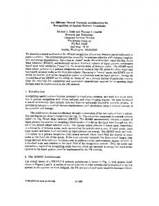
AN EFFICIENT PIPELINE ARCHITECTURE OF JPEG2000 MQ-CODER Huynh Ngoc Tuan1 , Hoang Trang2
Abstract The Embedded Block Coding with Optimized Truncation (EBCOT) consists of Bit-Plane Coding (BPC) and MQ-coder, is one of key algorithms of JPEG2000 compression system. However, this coder block takes the majority of compressing time because of individual bit processing routine. In this paper, the efficient pipeline architecture for MQ-Coder is introduced to achieve high operation frequency and 100% of the throughput. The pipeline technique based structure is proposed and allow the JPEG2000 compression system to achieve high clock rate, increase the data rate. In addition, the architecture uses Streaming Bus to synchronize pixel and bit-stream easily in the compressed image. The introduced architecture is implemented on different FPGA platforms and it operates at 151.68 MHz, processes 151.68 mega sample per second with the reasonable hardware resource (1373 LEs and 714 registers) on Altera - EP3SL50F484C2 FPGA platform. Trong hệ thống nén ảnh JPEG2000, EBCOT (Embedded Block Coding with Optimized Truncation) là một trong những thuật toán chủ đạo, thuật toán này bao gồm thuật toán mã hóa Bit-Plane và thuật toán mã hóa MQ. Tuy nhiên, bộ mã hóa EBCOT này tiêu tốn rất nhiểu thời gian trong quá trình nén ảnh bởi vì nó xử lý dữ liệu từng bit riêng lẽ. Bài báo này đưa ra kiến trúc đường ống cho bộ Mã hóa MQ nhằm đạt được hiệu quả cao về tần số và quá trình xử lý xuyên suốt 100%. Kiến trúc đề ra dựa vào kỹ thuật đường ống cho phép hệ thống nén ảnh JPEG2000 đạt được tốc độ xung nhịp cao dẫn đến tốc độ dữ liệu cũng tăng cao. Thêm vào đó, kiến trúc này sử dụng giao thức "điểm tới điểm" để đồng bộ hóa các điểm ảnh và chuỗi bit một cách dễ dàng. Bộ Mã hóa MQ được hiện thực trên các hệ thống FPGA khác nhau, tần số hoạt động là 151.68 MHz và tốc độ xử lý dữ liệu là 151.68 MSPS trên hệ thống FPGA Altera - EP3SL50F484C2 Index terms JPEG2000, MQ-Coder, Pipeline, VLSI.
1. Introduction HE JPEG2000, the still image compression, is the latest international standard, which not only has better compression ratios but also offers some new features (lossy and lossless compression, region of interest coding, rate control. . . ) in comparison to the previous compression techniques [1]. Therefore, this standard can be used in the multimedia field, the internet, medical devices and mobile applications. The key algorithms of the JPEG2000 include the Discrete Wavelet Transform (DWT), the scalar quantization, and the Embedded Block Coding with Optimized Truncation (EBCOT) that comprises of two coding procedures
T
(1) Integrated Circuit Design Research and Education Center-Vietnam National University - Ho Chi Minh City (2) Ho Chi Minh City University of Technology-Vietnam National University - Ho Chi Minh City
105
Chuyên san Công nghệ thông tin và Truyền thông - Số 02 (4-2013)
(BPC and MQ-Coder). The MQ-coder is based on a recursive probability interval subdivision and initialized with (0, 1). According to the probability of the decision, the interval will be partitioned into two subintervals (MPS and LPS). The interval register A provides the length of the current interval and the code-word register points to the base of the current interval. Depended on the decision, if it is LPS or MPS, these two registers will be updated according to the probabilities determined by the current context. The JPEG2000 gets the advantages of EBCOT, but the EBCOT takes the longest time of the computation process. In the EBOT, MQ-coder is the bottle-neck causing low performance [2].Various hardware architectures were introduced to improve the performance and the hardware resource of the MQ-Coder [2-7]. Because of the serial processing characteristic, it takes many cycles to process only one CX-D fair. Moreover, the critical paths are occurred in updating the Index and the More Probable Symbol. This reason is caused by updating process which is implemented basing on the Lookup Table [8]. The proposed architecture in [6] handles more than one CX-D pair in parallel to improve the performance of the MQ-Coder but the hardware resource (in slices) is large (6974 Slices). In the same way, the architecture in [2] improves both the hardware resource (in logic cell-LC) (1448 LCs) and the throughput by handling two CX-D pairs at the same time (58.6 MHz). On the contrary, another architecture tries to cut down the hardware resource (679 LEs) but the operation frequency and the throughput have not been considered yet so this design is not intended for high performance architectures [9]. In this paper, both performance and hardware cost are considered. The proposed architecture processes one CX-D pair at a time and applies the pipeline technique to get the higher performance in comparison to some previous ones [2,5,6,9]. After analyzing the MQ-coding algorithm, the 7-stage pipeline architecture has been introduced for achieving 100% of throughput and getting higher operation frequency. This method cuts down a lot of critical paths in the updated procedures and feedback signals, separates the coding flow to lead the simpler computation process in each stage. Therefore, the hardware resource (slices or logic cells) in every stage is kept reasonably meanwhile the performance is improved significantly. The proposed architecture is implemented on the Altera FPGA platform (Altera EP3SL50F484C2), operates at 151.68 MHz, uses 1373 Logic elements (LEs) and 714 logic registers (logic cells). The rest of this paper is organized as follows: the MQ-coder in JPEG2000, some difficulties in hardware implementation are introduced briefly in session II. The proposed architecture for the JPEG2000 MQ-coder is depicted in session III. Session IV describes the FPGA implementation and results. Finally, a conclusion is given in session V.
106
Tạp chí Khoa học và Kỹ thuật - Học viện KTQS số 153 (4-2013)
Figure 1. Block diagram JPEG2000
2. MQ-coder in JPEG2000 2.1. Overview of arithmetic coding The basic block diagram of JPEG2000 encoder is shown in Figure 1. The BPC produces CX-D pairs that are fed to the MQ-Coder. The decision bit (D) represents More Probable Symbol (MPS) or Less Probable Symbol (LPS). The context (CX) is used to determine the MPS value and index (I(CX)) based on the Probability Estimation Lookup Table (PET) [1]. The PET stores the probability values (Qe), next index for MPS (NMPS) or LPS (NLPS) renormalization and SWITCH. The MPS(CX) decides which procedure (MPS or LPS) is coded, and all initial values of MPS(CX) are zero. The SWITCH values indicate if a change of sense of MPS(CX) is needed. The main idea of arithmetic coding (MQ-coding) is to map the limited interval that can be presented by two registers (A and C). Register A provides the length of the current interval meanwhile register C stores the interval position and changes depending on value of D. When the value of register A becomes smaller, the high order bits of register C get fixed little by little and can be created into compressed bytes to output to the Tier-2 block. 2.2. MQ-Coding algorithm The overview of MQ-coder is shown in Figure 2. It processes CX-D pairs from BPC to produce a compressed data (CD) stream. The CD stream will be used in the Tier-2 coder that performs the layered bit stream organization. The implementation of MQ-coding uses one 32-bit interval register and one 32-bit codeword register. The structure of interval register (register A) and code-word register (register C) are described in detail in Coding of Still Pictures [10]. The initial value of register A and C are initialized with 0x8000 and 0x0000 respectively. It means that no code-word has been generated yet. The decision bit (D) and the value of MPS determine if CodeMPS or CodeLPS procedure is executed. After all CX-D pairs are processed, a FLUSH register procedure is 107
Chuyên san Công nghệ thông tin và Truyền thông - Số 02 (4-2013)
Figure 2. The overview of MQ-Coder
called to stuff many 1-bits as possible in register C before outputting the compressed data stream (CD). The MQ-coding process consists of Initialization, CodeMPS, CodeLPS, Renormalization, Byteout and FLUSH register procedure. The function of each procedure will be described below. The flowchart is shown in Figure 3. Initialization: to initialize the registers and variables for the MQ-coder. Besides, it also resets I(CX) and MPS(CX) with initial values which are presented in [8]. CodeMPS and CodeLPS: to adjust the size of the interval register and the code-word register. The new sub-interval for the MPS determines the conditional MPS/LPS exchange. The next index of context (I(CX)) is indicated by the variable NMPS(I(CX)) or NLPS(I(CX)). Renormalization: be always called after CodeLPS. However, in CodeMPS, it is only called if register A is less than 0x8000 after updating MPS. Register A and C are shifted one bit at a time until register A greater than or equal to 0x8000. The number of shifted bits is counted in the counter (CT), and when the CT is counted down to zero, the Byteout procedure is called to generate the compressed data (bytes stream). Byteout: to procedure the compressed data one byte once. The bit_stuffing and no_bit_stuffing are called inside this procedure to limit carry propagation into completed bytes. FLUSH register: the final procedure in MQ-coding algorithm, which terminates the encoding operations and generates the required terminating marker. This procedure is executed to stuff many 1-bits as possible into register C before outputting the final bytes as compressed data. 2.3. Difficulties in hardware implementation After scanning the MQ-coding algorithm, the hardware implementation of MQ-coder faces with some difficulties such as that coding process is carried out step by step, the current CX-D 108
Tạp chí Khoa học và Kỹ thuật - Học viện KTQS số 153 (4-2013)
Figure 3. MQ-coding flow
pair is coding based on the previous one, and the coding process takes many loops inside its procedure. These issues lead to the operation frequency is low (sequential coding), and the resource is high in hardware based implementation. Some approaches have been proposed to reduce the hardware resource and also improve the speed of the MQ-Coder [2,5,6,9]. The proposed architecture in [2], its operation frequency is higher than some other ones [5,6]. However, the hardware resource is not improved as good result (1488 LCs). In 2012, the new approach [9] is introduced, in which the hardware resource is improved impressively (679 LEs) but the high performance has not been considered yet (54.89 MHz). For these reasons, this work proposes the efficient pipeline architecture of JPEG2000 encoder which improves the performance (94.21 MHz) and keep the hardware resource effectively (2030 LCs).
109
Chuyên san Công nghệ thông tin và Truyền thông - Số 02 (4-2013)
Figure 4. MQ-coder interface
3. The proposed architecture 3.1. Overview of the Architecture The recent architectures proposed for MQ-Coder are divided into pipeline stages for obtaining high throughput, shared the resources for cutting down the hardware resource. In general, they can be classified into two main groups depending on their pipeline stages. First of all, the 3-stage pipelined architectures update the internal registers (A & C), probability estimation stage, Renormalization stage and Byteout stage. Secondly, the 4-stage pipelined architecture slits the register C into two parts (the low 16-bit and the high 12-bit) to shorten the critical path originated form the 28-bit adder. All arithmetic operations are processed in consecutive pipeline stages. In this session, the efficient pipeline architecture (7-stage architecture) is proposed to accelerate the encoding speed, to increase the data rate for JPEG200 MQ-Encoder. Even though the number of pipeline stages is larger than the previous ones, the hardware resource is kept in the reasonable limitation. The proposed architecture completely complies with standards of an IP core. Hence, it is important to choose a bus interface to integrate into proposed architecture. The Avalon Streaming Interface [10] is employed because it owns some advantages such as common use, point – point connection and simple design. The top view of the proposed architecture is given in Figure 4. The 7-stage pipeline architecture is organized for whole computation process. The first stage (L1) computes the register A, updates MPS(CX), LPS(CX) and I(CX), based on the BAC Qe-value and Probability Estimation Lookup Table [8]. For the value of register A and the Lookup Table in the first stage, the second stage (L2) updates the register C (the low 16-bit), calculates the jumping condition to move to Renormalization procedure. In the third stage (L3), the Renormalization procedure is taken place, the rest of register C, the number of shifted bits (CT) in register A and the register B (Byteout) are processed concurrently. The fourth stage (L4) slits the data flow into two parts for calculating the output data in the Byteout procedure and the value of register C in the next step. Currently, all necessary data for FLUSH register have been available in two parts of the data flow. The sixth stage (L6) merges two separable parts (two data streams) into ones. Finally, L7 stage handles all 110
Tạp chí Khoa học và Kỹ thuật - Học viện KTQS số 153 (4-2013)
Figure 5. Stage diagram of proposed architecture
computation process in FLUSH register procedure to output the compressed data (byte). The working flow is described in Figure 5.
111
Chuyên san Công nghệ thông tin và Truyền thông - Số 02 (4-2013)
Figure 6. MPS updating process
Figure 7. Index updating process
3.2. L1 stage Based on the input data (CX-D), the previous MPS(CX) and SWITCH values in Memory (PET) to update the current MPS(CX). The detailed circuit is described in Figure 6. The current MPS(CX) chooses which coding procedure (CodeMPS or CodeLPS) will be executed. The updated mechanism of I(CX) is given in Figure 7.
112
Tạp chí Khoa học và Kỹ thuật - Học viện KTQS số 153 (4-2013)
Figure 8. 16-bit low order updating
Figure 9. Jumping condition
3.3. L2 stage This stage uses the available data from the previous stage to calculate 16-bit low order in register C and the condition to jump into the Renormalization stage (L3)as in Figure 8 and Figure 9. If the CodeMPS coding is executed, the jumping condition will depend on the value of register A. On the contrary (CodeLPS), the jumping condition is always true. 3.4. L3 stage In this stage, the Renormalization procedure, the number of shifted bits, the 12-high order in register C and the first Byteout procedure are executed as the same time. This stage uses the data from previous stages, optimizes the logic circuit to predict value of CT. The prediction process, the C updating circuit and the register B updating are shown in Figure 10, Figure 11 and Figure 12 respectively. 3.5. L4 stage This stage slits the main data stream into two streams. A stream transfers the value of register B meanwhile another one conveys the value of shifted bits (CT) and the value of register C. Register C in FLUSH register procedure is first updated in this stage. The description is displayed in Figure 13 and Figure 14. 3.6. L5 stage – L6 stage The Byteout procedure is again executed in this stage. The computed value of register B will be used in the FLUSH register procedure. Two data streams contain the previous value of register B and the current value of register B. In whole coding procedure, Byteout is called 113
Chuyên san Công nghệ thông tin và Truyền thông - Số 02 (4-2013)
Figure 10. CT predicting circuit
Figure 11. Register C updating process (12-bit high order)
3-time so once is computed in L3 stage, twice in this stage. After L5 stage, the system has enough sufficient data for the final stage (FLUSH register procedure). Because of two updated data streams of register B, it is necessary to merge together and forward to the final stage. The updating process of Byteout is described as below in Figure 15 and Figure 16. 3.7. L7 stage Now, the system has all necessary data to execute the FLUSH register procedure. The updated process of register B and register C have been completed before. The values of register B are the compressed bytes. However, based on the number of shifted bits of register C in the previous stage and the final packet information, the number of compressed bytes is outputted as the compressed code-words (bytes) as in Figure 17.
114
Tạp chí Khoa học và Kỹ thuật - Học viện KTQS số 153 (4-2013)
Figure 12. Register B updating process
Figure 13. Register C updating of FLUSH in the first stream
Figure 14. First Byteout in the second stream
115
Chuyên san Công nghệ thông tin và Truyền thông - Số 02 (4-2013)
Figure 15. Second Byteout
Figure 16. Third Byteout
4. MQ-coder implementation and result The proposed architecture has been described in the Verilog HDL, simulated the functionality using Synopsys VCS environment, synthesized on different tools (Xilinx ISE and Altera Quartus). The latency of the proposed architecture are presented in the Table 1. The latency in number of cycles is large but this architecture gets 100% of throughput because the latency only exists at the beginning of the encoding process. Moreover, in order to verify the operation of the proposed architecture, a golden model using C language and another one using Matlab based on the MQ-coding algorithm are also built. The verification method is to generate a mass of test cases, (CX-D pairs) to feed them into the golden model and the
Figure 17. CD stream
116
Tạp chí Khoa học và Kỹ thuật - Học viện KTQS số 153 (4-2013) Table 1. The Latency of the proposed architecture Stage L1 L2 L3 L4 L5 L6 L7 Avalon interface Total
Latency (cycle) 2 1 3 1 3 2 1 4 17
design of this work. If output data (Bit stream) from the design match the output data from the golden model, it means that the operation of the proposed architecture is correct. In this case, over five hundred random CX-D pairs are automatically generated and the successful simulation report is obtained. Compared to some recent designs, the performance of proposed architecture in this work is improved significantly. The introduced architecture in [9] focused on minimizing the size of internal registers, the Lookup Table (PET) and optimizing the full adder to reduce the hardware resource, to obtain the high performance. However, the pipeline architecture has not been applied yet, it means that the performance of this design was not high as the expectation (54.888 MHz). On the contrary, the hardware resource and the performance are balanced. Therefore, the pipeline architecture is proposed to slit the encoding process in seven stages. Each stage has the specific role such as the first stage updates the MPS(CX), I(CX) and the half of register A, the second stage computes the rest of register A and the half of register C... This solution helps to cut down the critical paths, to improve the operation frequency considerably. The operation frequency comparison result was shown in Table 2. In another aspect, the hardware resource is one of criterion to evaluate the efficiency of a design. A previous design introduced a novel architecture to get high throughput by processing two CX-D pairs in parallel. This design obtained 48.3 MHz and the throughput reached 96.6 mega sample per second (MSPS) [6]. The performance was improved impressively but it used a large number of slices (the hardware resource) for eight different processing elements, four pipeline stages, 32-bit internal register (must use 32-bit adder, 32-bit buffer width. . . ), a huge combinational logic to predict the real A and C values, to process two CX-D pairs concurrently. In this design, the pipeline technique is also used to increase the performance. However, this work still keeps the reasonable hardware resource by cutting down the bit width of adders, slitting internal registers suiting the adders, and nearly applying adders for whole arithmetic operation in the design. The maximum bit width of adder is 16-bit instead of 28-bit in [2]. Table 3 shows the hardware resource comparison result, in which hardware resource consists of Slice Flip Flops & LUTs in Xilinx ISE, or logic register & combinational logic in Altera Quartus.
117
Chuyên san Công nghệ thông tin và Truyền thông - Số 02 (4-2013) Table 2. Frequency, throughput comparison Architecture Frequency (MHz) Throughput (MSPS) FPGA device This work/[9] 94.21/54.888 Altera - EP2S90F1020I4 This work/[2] 94.21/58.56 94.21/117.12 Altera - EP2S90F1020I4 This work/[6] 105/48.30 105/96.06 Xilinx - XC4VLX80 *Note: The work in [9] did not show the throughput report. Because the throughput of a design is determined dependently on the FPGA devices, for the comparison purpose, this design is also synthesized with Altera - EP2S90F1020I4 and Xilinx - XC4VLX80 which are compatible with [2] and [6] respectively.
Table 3. Hardware resource comparison Architecture This work/[2] This work/[6] This work/[5]
Max bit width adder (bit) 16/32 16/32 16/32
Resource 2030/1488 2245/6974 2250/2504
FPGA device Altera EP2S90F1020I4 Xilinx XC4VLX80 Xilinx XC3S700A
5. Conclusion In this paper, the arithmetic coding, MQ-Coding algorithm are briefly described and the implementation of this algorithm in the MQ-encoder architecture is presented. This design is separately implemented on synthesis tools (Xilinx ISE & Altera Quartus) with different devices (Xilinx - XC3S700A, Altera - EP2C20F484C6. . . ) for comparison purpose. Efficient pipeline architecture, the 7-stage pipeline architecture is proposed to achieve the throughput 100%, to get the higher performance and the reasonable hardware resource. The operation processes, updating internal registers (A and C), predicting the next index (I). . . in the MQ-Coding algorithm are computed in the different stages. Hence, compared with other architectures, the operation frequency of this design is improved significantly, also the throughput and hardware resource. This architecture has been implemented in the JPEG2000 encoder project and the operation frequency reaches 151.68 MHz with Altera - EP3SL50F484C2 FPGA platform.
References [1] ISO/IEC 15444-1,Information Technology-JPEG2000 Image Coding System, Part 1: Core Coding System, 2000 [2] PENG Zhou, ZHAO Bao-jun, High-throughout hardware architecture of MQ arithmetic coder, International Conference on Signal Processing (ICSP), October, 2010, pp. 430-433 [3] Michael Dyer, David Taubman, Saeid Nooshabadi, Improved throughput arithmetic coder for JPEG2000, International Conference on Image Processing, vol. 4, October, 2004, pp. 2817-2820 [4] Manjunath Gangadhar, Dinesh Bhatia, FPGA based EBCOT architecture for JPEG 2000, International Conference on Field-Programmable Technology (FPT), December, 2003, pp. 228-233 [5] Taoufik Saidani, Mohamed Atri, Rached Tourki, Implementation of JPEG 2000 MQ-Coder, International Conference on Design and Technology of Integrated Systems in Nanoscale Era, March, 2008, pp. 1-4 [6] Kai Liu, Yu Zhoub,Yun Song Li,Jian Feng Ma, A high performance MQ encoder architecture in JPEG2000, the VLSI Journal, vol. 43, no. 3, June, 2010, pp. 305-317 [7] Minsoo Rhu, In-Cheol Park, Optimization of Arithmetic Coding for JPEG2000, IEEE Transactions on Circuits and Systems for Video Technology, vol. 20, no. 3, March, 2010, pp. 446-451
118
Tạp chí Khoa học và Kỹ thuật - Học viện KTQS số 153 (4-2013) [8] Tinku Acharya, Ping-Sing Tai, JPEG2000 Standard for Image Compression: Concepts, Algorithms and VLSI Architectures, New Jersey, U.S.A: John Wiley & Sons, chapter 5, 2005, pp. 185-195 [9] Wael M. El-Sharkasy, Mohamed E. Ragab, Hardware modelling of JPEG2000 MQ-encoder, International Conference on Intelligent and Advanced Systems (ICIAS), vol. 2, June, 2012, pp. 707-712 [10] Altera, Avalon Interface Specifications, California, U.S.A, 2011, pp. 35 - 44 [11] Altera, Stratix III Device Handbook, California, U.S.A, 2011
Ngày nhận bài 7-5-2012; ngày gửi phản biện 8-5-2012. Ngày chấp nhận đăng 5-6-2013.
�
Huynh Ngoc Tuan received the B.S. degree in Electronics and Telecommunication Engineering from Can Tho University, in 2009. From 2010 to 2012, he was a hardware designer in Renesas Electronics Corporation where he designed and verified the SoC Chip. He is currently working at ICDREC, pursuing M.S. degree at Ho Chi Minh City University of Technology, and focuses on FPGA based hardware implementation for video and digital image processing algorithm.
Hoang Trang was born in NhaTrang city, Vietnam. He received the Bachelor of Engineering, and Master of Science degree in Electronics-Telecommunication Engineering from Ho Chi Minh City University of Technology in 2002 and 2004, respectively. He received the Ph.D. degree in MicroelectronicsMEMS from CEA-LETI and University Joseph Fourier, France, in 2009. From 2009-2010, he did the post-doctorate research in Orange Lab-France Telecom. Since 2010, he is lecturer at Faculty of Electricals-Electronics Engineering, Ho Chi Minh City University of Technology. His field of research interest is in the domain of FPGA implementation, Speech Recognizer, MEMS, fabrication, integration of passive components and function for telecommunications, Embedded System, System-on Chip (SoC).
119