AN EFFICIENT REFORMULATION BASED VLSI ARCHITECTURE FOR ADAPTIVE VITERBI DECODING IN WIRELESS APPLICATIONS Yao Gang,Tughrul Arslan,Ahmet Erdogan School of Electrical Engineering, Edinburgh University Edinburgh UK, EH93JL Email:
[email protected] ABSTRACT
combined requirement of the low energy, high performance and considerable flexibility in FEC design. When channel is in good state, the computation efforts for FEC decoding should be reduced. Such issues have been identified in [3]. Chan [4] proposed an efficient FEC scheme referred to Adaptive Viterbi Algorithm VA (AVA), which computed the received channel symbol adaptively according to the channel environment. Up till now, Sriram’s work [5] is the only one that described the VLSI architecture of AVA algorithm in literature. In this paper, we focus on the Add Compare Select (ACS) unit of AVA, which is the major component for adaptaive Viterbi Decoder. In [5], the minimum path metric is stored into the Path Metric Memory Unit (PMU) in the current iteration of the trellis recursion and are read out for calculating the path metric and determing the survivor state in the next iteration. Through reformulated AVA, a significant hardware reduction is achieved both in standard cell based ASIC and Look Up Table (LUT) based FPGA technologies. The paper is organized as follows: In section II, we briefly describe the AVA algorithm and conventional approach by Sriram [5]. Our reformulated scheme is described and discussed extensively in section III. In section IV, we present the area, energy and speed simulation results on both ASIC and FPGA platforms.
New trends in wireless communication systems has dictated the need for dynamical adaptation of communication systems in order to suit enviromental requirements. The authors present a reformulation based VLSI architecture for threhold selection for Adaptive Viterbi Decoding in wireless applications. Through reformulation of the Adaptive Viterbi Algorithm, the compare operation for threshold selection in Add Compare Select (ACS) unit is simplified from variable based to constant based and the width of path metric is reduced. The reformulated architecture results in a significant reduction of hardware complexity in both standard cell and Look Up Table (LUT) technologies. The paper describes the reformulation technique, its VLSI Architecture for Adaptive Viterbi Decoding and its implementations in both ASIC and FPGA technologies. We also demonstrate that in additon to significant reduction in data path complexity, there is also a 25% to 47% storage reduction in the Path Metric Memory Unit (PMU). 1. INTRODUCTION Wireless networks usually employ sophisticated Forward Error Correction (FEC) techniques such as Viterbi Algorithm [1] to combat with the channel distortion effects such as multipath fading and intersymbol interference. The computation complexity and storage requirement of the conventional Viterbi Algorithm (VA) increased exponentially with the constraint length in the current wireless applications [1]. For example,the number of the visited states is 64 in Wireless LAN protocol and 256 in 3G protocol. On the other hand, combining cost, performance and energy-efficiency is an important design aspect for the future wireless systems [2]. Considering the strict constraints on the area and the power in the mobile systems especially the battery based handsets, it is prohibitively complex to implement the conventional FEC scheme based on VA. The strategy of adaptation with the changing channel conditions is a promising method to resolve the problem of
0-7803-8504-7/04/$20.00 ©2004 IEEE
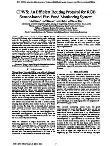
2. ADAPTIVE VITERBI ALGORITHM The well-known VA has been described in literature extensively. The data path of the Viterbi Decoder is composed of three major components: Branch Metric Calculation Unit (BMU), ACS and Survivor Memory Unit (SMU) as shown in Fig 1. The branch metrics are calculated from the received channel symbols in BMU and then fed into the ACS which performs Add-Compare-Select for all the states. The decision bits generated in ACS are stored and retrieved in the SMU in order to finally decode the source bits along the final survivor path. The state metrics of the current iteration are stored into the Path Metric Memory Unit (PMU) and read out for the use of the next iteration.
206
SIPS 2004
channel Symbol
BMU
Branch Metric
ACS
Decision Bits
SMU
t=0 t=1 t=2 t=3 t=4 t=5
Decoded Output
State Metrics
x
00
Path Memory
1
2
01
Fig. 1. Top Level Block Diagram Of Viterbi Decoder
1
10
In ACS unit, the VA examines all possible paths in the trellis graph and determines the most likely one. The AVA only keeps a number of the most likely states instead of the whole of 2K−1 states, where K is the constraint length of the convolution encoder [1] [4]. The rest of the states are all discarded. The selection is based on the likelihood or metric value of the paths, which for a hard decision decoder is the Hamming distance and for a soft decision decoder is Euclidean distance. The rules of the selecting the survivor path is :
x x
1
2
2
2 x
4
3
1 x 2 x 2
2
x x
11 01
10
11 3 01 2 00 3
dm=0 dm=1 dm=1 dm=1 dm=2
Trellis States
Fig. 2. Trellis Graph Of Adaptive Viterbi Decoding
ADDER #0 ADDER #1
1. Every surviving path at trellis level n is extended and its successors at level n+1 are kept if their path metric are smaller or equal to P Mnmin + T , where P Mnmin is the minimum path metric of the surviving path at stage n + 1, and T is the discarding threshold configured by the user.
PATH METRIC ADDER
Threshold Selection Unit
Survivor State Contender
State Merge
Added_Path_Bus
...
ADDER #2Nmax-1
Min Path Calculation Adaptive ACS Architecture
2. The total number of survivor paths per trellis stage is up bounded to a fixed number: Nmax , which is preset prior to the start of the communication.
Fig. 3. Block Diagram Of Adaptive ACS Architecture
In order to illustrate how the AVA operates, an example using a code rate R = 1/2, constraint length K = 3 is given in Fig 2. The threshold T is set to 1 and Nmax is set to 3 respectively. Initially at t = 0, we set the P Mnmin equal to 0 and the decoder states equal to 00. The received sequence is {01, 10, 11, 01, 00}. The symbol X represents the discarded path and bold line represents the final decision path by the AVA algorithm. For the sake of the simplicity, the minium path metric of the nth iteration P Mnmin is denoted by dm . It can be seen that at each trellis stage, the number of the survivor states is smaller than the VA (2K−1 ) and gets the same decision paths as the VA. The optimal selection strategy for architecture parameter Nmax and T is discussed in detail in [4] and [5]. In this paper, a range of T from 20 to 30 and a range of Nmax up to 2K−2 [5] is considered. The top level block diagram of ACS unit of AVA Decoder is shown in Fig 3. Path Metric Adder and State Merge Unit correspond to the operation of Add and Compare-Select Operation in VA respectively. Compared to conventional VA [1], two additional processing units are inserted into the data path of the VA: Threshold Selection and Survivor Contender which correspond to the AVA rule 1 and rule 2 respectively in AVA architecture. The Threshold Selection unit discards the paths exceeding the sum of the preset value T and the minium path metric of the last iteration
P M min and the survivor contender is responsibile for sifting Nmax states out of 2Nmax states. In addition, Min Path Calculation unit is responsibile for calculating the minium path of the current iteration. The conventional Threshold Selection architecture [5] is shown in Fig 4. At time step n, the path metric of state i dennoted as P Mni and the branch metric from BMU, dennoted as BM ij associated with a state transistion from i to j are added in the path metric adder. The accumulated path metj is compared to the sum ric of state j , dennoted as P Mn+1 min of P Mn and pre-set constant T . Those exceeding will be discarded. In parallel to the operation of the Threshold Selection Unit and Survivor State Contender, the path metj is fed into the Min Path Calculation ric of state j, P Mn+1 for determining the minium path metric of current iteration min ,which is stored for the use of next iteration. P Mn+1 3. REFORMULATED APPROACH 3.1. Algorithm Reformulation Let i, j ∈ S represent the states of the trellis graph and state i is the preceding state of state j associated with a state transition from i to j. Let P Min represents the accumulated path metric of state
207
4
BM ij PM n
Table 1. Comparsion Function Based On Standard Cell Technology( T = 20)
+
i
8
PM n
PM n+1 j
4
T
+ PM n+1 min Min Path Calculation
8
Fig. 4. Threshold Selection Unit architecture : conventional
Power
Delay
a