Tamkang Journal of Science and Engineering, Vol. 7, No 4, pp. 241-250 (2004)
241
An Efficient VLSI Architecture for Rivest-Shamir-Adleman Public-key Cryptosystem Jen-Shiun Chiang*, Cheng-Chih Chien, Jian-Kao Chen and Hsin-Guo Chou Department of Electrical Engineering Tamkang University Tamsui, Taiwan 251, R.O.C. E-mail:
[email protected]
Abstract In this paper, a new efficient VLSI architecture to compute modular exponentiation and modular multiplication for Rivest-Shamir-Adleman (RSA) public-key cryptosystem is proposed. We modify the conventional H-algorithm to find the modular exponentiation. By this modified H-algorithm, the modular multiplication steps for n-bit numbers are reduced by 5n/18 times. For the modular multiplication a modified L-algorithm (LSB first) is used. In the architecture of the modified modular multiplication the iteration times are only half of Montgomery’s algorithm and the H-algorithm. The proposed architecture for the RSA public-key crypto-system has a data rate of 146 kb/s for 512-b words with a 200-MHz clock rate. Key Words: Data Security, H-algorithm, L-algorithm, Modular Exponentiation, Modular Multiplication, Montgomery’s Algorithm, Public-key Cryptosystem, RSA, VLSI
1. Introduction In open network and communication systems, the security problems of electronic communication are severe. Traditionally, the common algorithm (common key) is used to improve the security problems. In the common algorithm approach, the transmitter encrypts codes by a secret key; the receiver uses the same (common) key to decrypt the received data. However, a problem is concerned: how to send the secret key between transmitter and receiver. In 1978, Rivest, Shamir, and Adleman (RSA) [1] proposed a public key cryptosystem to improve the communication security problem. In the public key cryptosystem, people use a public key to encrypt the code and transmit the data to the receiver. The receiver uses the private key to decrypt the received data. The public key can be retrieved by anybody, but the private *Corresponding author
key is held by the receiver only. By this arrangement, people do not need to worry about the key transmission problem, and thus can improve the communication security significantly. The public key cryptosystem uses a mathematical theory to map data in one way direction, f(X): X ® Y, and makes the inverse transform f -1(Y); Y ® X to be very difficult. The RSA cryptosystem [1] uses Euler and Fermat theorem [15]; its security is based on the decomposition of a number, N, that is the multiplication product of two distinct prime numbers. It is known that a large number is very difficult to decompose. For applications, the RSA cryptosystem cannot only be applied to electronic data communication, but also for electronic signature [1]. The safety of the RSA cryptosystem depends on the length of the key, usually the longer the key the more safety the data. Generally we need at least a 512-bit key. The processing of the key is composed of many modulo multiplication, modulo addition, and modulo exponentiation
242
Jen-Shiun Chiang et al.
operations. The RSA cryptosystem is briefly described as follows: Let p and q be two distinct large random primes and a number N; denote N=p×q Let us choose a large random number d > 1 such that gcd[(p - 1)(q - 1), d] = 1, and compute the number e, 1 < e < (p - 1)(q - 1), e × d / 1 (mod(p - 1)(q - 1), The numbers N, e, and d are called modulus, encryption, and decryption exponent respectively. The numbers N and e constitute the public encryption key, and p, q, (p - 1)(q - 1) and d form the secret trapdoor. To encrypt and decrypt, the input text is first encoded to a number and is divided into blocks of suitable size. The blocks are then processed separately as follows: C = Me (mod N) M = Cd (mod N)
(1) (2)
C and M are referred to as ciphertext and plaintext blocks, respectively. Equations (1) and (2) are in modular exponentiation operation and are the most critical operation in RSA. Therefore, how to increase the speed of the modular exponentiation is the main task for the RSA public-key cryptosystem. Basically the modular exponentiation needs modular multiplication. The modular multiplication is accomplished by addition and shift operations. Since the numbers that we deal with are large numbers ($ 512 bits), it is much different from the traditional number multiplication. In RSA we need modular multiplication and modular exponentiation, therefore, after the multiplication the modulus adjustment has to be operated, and that makes the calculation even more difficult than the calculation of normal numbers. The modulus adjustment is usually accomplished by range comparison. For real time operation, we have to use special methods to calculate the modular multiplication and exponentiation [16]. To reduce the time complexity for comparison, a modular multiplication algorithm based on Montgomery’s modular arithmetic [17] was proposed by Eldridge [7]. The Montgomery’s algorithm is very suitable for systolic array architecture [4,5,8,18]. Although the systolic array has the characteristic of regularity in the VLSI layout, the
hardware cost is high [11,12,13]. Another approaches are H-algorithm (MSB first) [2,5,10] and L-algorithm (LSB first) [10]. These two algorithms are the basic algorithms for modular multiplication. Although the speed is slower than Montgomery’s algorithm, the hardware cost is lower than the Montgomery’s algorithm. In this paper, we modify the L-algorithm to calculate the modular multiplication [19]. The modified L-algorithm can increase the calculation speed twice faster than the conventional L-algorithm, and the hardware cost is almost the same. Montgomery’s algorithm, H-algorithm, and L-algorithm are usually applied to calculate the modular exponentiation. Like the modular multiplication, Montgomery’s algorithm for calculating modular exponentiation takes more hardware. Here we use a modified H-algorithm [19] to calculate the modular exponentiation. For an n-bit number, this approach can reduce 5n/18 iteration times. In the hardware design of this RSA cryptosystem, adders are massively used. To avoid unnecessary carry propagation, addition can be accomplished by the redundant binary adders [2] or carry save adders [3-6]. However, the adder cell of the redundant binary adder is very complicated, and we use carry save adder for this design. In the shift operation, there are two approaches, left shift (multiply by 2) [2,5,6] and right shift (divide by 2) [3,4]. In this paper, we use the left shift approach. The modular operation can be finished by comparators or by checking the overflow of the adder [5,6]. The former approach needs more hardware and the speed is slower. The latter approach needs less hardware and the speed is faster. Therefore, we use the latter approach to implement the modular operations. In order to reduce the hardware cost, the calculating data (message) of our design are divided into four segments, and each time only one segment is operated. The time to calculate a modular exponentiation is 2.65n2 clock cycles. By the proposed approaches we designed a RSA processor; the data rate is about 146 kb/s for 512-b words with 200MHz clock frequency. This paper is organized as follows. In Section 2, the modified modular exponentiation algorithm is described. The modified modular multiplication algorithm is described in Section 3. The modular operation is shown in Section 4. The hardware design of the RSA cryptosystem and the simulation results are explained in Section 5. Finally we give the conclusion in Section 6.
An Efficient VLSI Architecture for Rivest-Shamir-Adleman Public-key Cryptosystem
2. Modified Modular Exponentiation Algorithm Repeating squaring and multiplying are the basic arithmetic operations for computing modular exponentiation. To compute C = Me (mod N), the conventional H-algorithm operates as follows [10]: // The H-algorithm (MSB first) // Me (mod N); P0 = 1; for (i = n - 1; i > = 0; i - -){ Mn-i = P2n-i-1 (mod N) if (ei == 1) Pn-i = Mn-i × M (mod N); else Pn-i = Mn-i } where e = [en-1, en-2, …e1, e0]2 is the encryption key, and Pi is the partial product. In the modular operation, ‘1’ needs two iteration steps in e[]. In the worst case, we need 2n steps to compute the exponentiation. In order to reduce the iteration times, we partition the encryption key e[] into several segments, and each segment consists of four bits; e[i] denotes the ith segment of e[]. Observing the bit patterns of the 4-bit segment, we find some rule to reduce the iteration times. For example, when e[i] = 0000, the computation of M e (mod N) in the H-algorithm needs squaring four times of M, and e[i] = 0001, the computation of M e (mod N) in the H-algorithm needs squaring three times and the 1 may be combined with next segment. Generally there need five iteration times at most in each segment. Whereas e[i] = 0111, the operation needs seven iteration times with the traditional H-algorithm. By bit patterns of this 4-bit segment, the computation sequences of C = M e (mod N) within this 4-bit segment can be summarized in Table 1. Let us describe the notation and operation of Table 1. Suppose X denotes the partial exponentiation of M e (mod N) in the H-algorithm of the modular exponentiation. In Table 1, 010 means X 2 (mod N); 001 means X × M (mod N); 011 means X × M 3 (mod N); 101 means X × M 5 (mod N); 111 means X × M 7 (mod N). In the hardware implementation, we can pre-calculate M1 = M (mod N), M3 = M3 (mod N), M5 = M 5 (mod N), and M7 = M 7 (mod N), and store these three n-bit numbers to tables. Let us take an example to describe the rules. Suppose three 24-bit numbers N, M, and e are given as follows:
243
N = 6012707 = 5bbf2316 = (0101 1011 1011 1111 0010 00112); M = 5234673 = 4fdff116 = (0110 1111 1101 1111 1111 00012); e = 3674911 = 38131f16 = (0011 1000 0001 0011 0001 11112). By our modified H-algorithm, e is partitioned into six 4-bit segments, and they are e[5] = 0011, e[4] = 1000, e[3] = 0001, e[2] = 0011, e[1] = 0001, and e[0] = 1111 respectively. e[5] = 0011, therefore initially P5 = M 3 (mod N). Then we proceed to next segment, e[4]. Since e[4] = 1000, from Table 1, we can find the sequences of operation are square, multiply by M, square, square, and square, i.e., P4 = [[[[P52 (mod N)]@ M (mod N)]2 (mod N)]2 (mod N)]2 (mod N). Next the procedure proceeds to e[3]. Since e[3] = 0001. Table 1 shows that the sequences are square, square, and square respectively. The LSB of e[3] is combined with next segment. Here we find the partial exponentiation as follows: P3 = [[P42 (mod N)]2 (mod N)]2 (mod N). Since the LSB of e[3] is combined with e[2]; the sequences of e[2] are square, multiply by M, square, square, square, square, and multiply by M3 respectively. The partial exponentiation is as follows: P2 = [[[[P32 (mod N)]2 (mod N)]2 (mod N)]2 (mod N) @M 3 (mod N). Table 1. The encryption key table 0000 0001 0010 0011 0100 0101 0110 0111 1000 1001 1010 1011 1100 1101 1110 1111
010 010 010 010 010 010 010 010 010 010 010 010 010 010 010 010
010 010 010 010 010 010 010 010 001 001 010 010 010 010 010 010
010 010 010 010 001 010 010 010 010 010 010 010 011 011 010 010
010 010 010 011 010 010 010 101 101 010 010 111 111
011 010 101 010 111 010 010 010 010
244
Jen-Shiun Chiang et al.
The next procedure proceeds to e[1]. The LSB of e[1] will be combined with e[0], and the rest of the sequences of e[1] are square, square, and square respectively. The partial exponentiation is as follows: P1 = [[P22 (mod N) ]2 (mod N)]2 (mod N). Then the next procedure is e[0]. The first two MSB’s of e[0] are combined with the LSB of e[1], and the sequences are square, square, square, and multiply by M7. The partial exponentiation is as follows: P0 = [[P12 (mod N)]2 (mod N) ]2 (mod N) @M7 (mod N) The sequences of the final procedural are square, square, and multiply by M3. The final exponentiation is: Pf = [P02 (mod N)]2 (mod N) @M3 (mod N) By the above description, the sequences of the exponentiation are: 3 2 1 2 2 2 2 2 2 2 1 2 2 2 2 3 2 2 2 2 2 2 7 2 2 3 7. Where ‘1’ means multiplying M1 to the partial exponentiation; ‘2’ means square of partial exponentiation; ‘3’ means multiplying M3 to the partial exponentiation; ‘7’ means multiplying M7 to the partial exponentiation. The sequences are shown in Table 2, and the results are shown in Table 3. By the above arrangement, [111] can reduce 2 iteration times, and [011] and [101] can reduce 1 iteration time. In the worst case, the iteration times of the modular multiplication of this approach are 4n/3, and the multiplication average times are 11n/9. Compared to Table 2. Sequences of the partial exponentiation
P5 P4 P3 P2 P1 P0 Pf
e[5]
e[4]
e[3]
e[2]
e[1]
e[0]
0011 0011 0011 0011 0011 0011 0011
1000 1000 1000 1000 1000 1000 1000
0001 0001 0001 0001 0001 0001 0001
0011 0011 0011 0011 0011 0011 0011
0001 0001 0001 0001 0001 0001 0001
11112 11112 11112 11112 11112 11112 11112
3 21222 222 2122223 222 2227 223
Table 3. Results of C = Me (mod N), with N = 5bbf2316, M = 4fdff116, and e = 38131f16 M1 M3 M5 M7
17ccd216 37660c16 5d68216 2a1d8c 16
the conventional H-algorithm (worst case = 2n, average = 3n/2), our approach reduces the multiplication times significantly.
3. Modified Modular Multiplication Algorithm In the modular multiplication, the Montgomery’s algorithm [3,4] or the H-algorithm [2,5] is applied widely. However, they have their drawbacks in the proposed architectures [11,12,13]. Here we would like to use a modified L-algorithm (LSB first) to find the modular multiplication. The conventional L-algorithm [10] is described as follows. // L-algorithm (LSB first) // A × B (mod N); P0 = 0, M0 = A; for (i = 0; i < = n - 1; i + +){ if (bi == 1) Pi+1 = Pi + Mi (mod N); else Pi+1 = Pi; Mi+1 = Mi > 2 shc4
shc1 shs4
shs1
shc3
shc2 shs3
M1
shs2
M3
M5
Figure 3. Tables and shift register.
M7
248
Jen-Shiun Chiang et al.
dataout(s)
Partial Product Adder
Table and Shift Register
Controller
Summand Generator
datain
Figure 4. RSA processor.
To compute the partial product in the correct range, the summands of the final modular multiplication are set to zero.
used to store B and put M1, M3, M5, M7, and k1 ~ k6 to the Table. Where B is the initial output of the partial product in each modular multiplication.
5.3. Table and Shift Register Figure 3 shows the block diagram of Table and Shift Register. The Table block stores precalculated values of M1, M3, M5, M7, and k1 ~ k6. While Shift Register is Table 7. Features of our RSA chip Design Tool
Verilog-XL
Synthesis Tool Synopsys Technology Cell Library Compass Standard Cell Library Process Technology TSMC 0.6 mm 1P3M Process Power Supply 5V Gate Counts (2 input NAND) 80550 Die Size 5304.0 mm ´ 5356.8 mm I/O 20-bit parallel, synchronous Baud Rate (512-bit) 146 kbits/s with 200 MHz (worst case) Voltage 5V Power consumption N/A
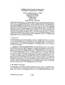
Figure 5. VLSI Layout of the 512-bit RSA chip.
Table 8. Features of four RSA chips
Clock Speed Baud rate Per 512 bits Clock Cycles Per512Bits Encryption Technology Bits Per Chip Gate Counts
Victor [20]
NTT [21]
Chen [22]
This Chip
25 MHz 100 K 0.125 M 1 mm 512 75 K
40 MHz 20 K 1M 0.5 mm 1024 105 K
50 MHz 24.3 K 1.05 M 0.8 mm 512 78 K
200 MHz 146 K 0.7 M 0.6 mm 512 80 K
An Efficient VLSI Architecture for Rivest-Shamir-Adleman Public-Key Cryptosystem
Table 9. Hardware requirement for various architectures Authors [3] [3] [6] [6] [7] [8] [9]
Wang I Wang II Sheu I Sheu II Eldridge Wu Juang Ours
Fas 2n 4n 3.18n 3.38n 3n + A1* 2n + A2* 2n 1.5n
Hardware Requirement REGs MUXs RAM 13n 26n 10.24n 13.88n 16n 12n 14n 6.75n
10n 20n 9n 19.1n 9n 6n 10n 4n
0 0 0 0 0 512 ´ 512 10 ´ 512 10 ´ 512
*A1 = n and A2 = log2(n + 1) represent the number of used half adders.
Table 10. Time complexity for various architectures Authors [3] [3] [6] [6] [7] [8] [9]
Wang I Wang II Sheu I Sheu II Eldridge Wu Juang Ours
Addition 1.5n2 n2 2.4n2 2.5n2 4n2 2n2 6n2 2.67n2
Time Complexity Comparison Cycle time No No Simple Simple Simple No Simple Simple
FA FA 2FA FA 2FA FA FA FA
5.4. RSA Processor Figure 4 shows the architecture of the RSA processor. We use Compass standard cell library (TSMC 0.6um process) to design a 512-bit RSA processor. The design is simulated by Compass ISM (input slope model) delay model. The simulation results show that the critical path delay is only 5ns, and the chip can operate up to 200MHz clock. The processor delivers a baud rate of 146 kbits/s in the worst case. The features of our RSA processor are shown in Table 7, and the features of four RSA chips are shown in Table 8. Otherwise, Figure 5 shows the layout of the RSA chip. The comparisons of hardware requirement and time complexity of the mentioned algorithms are listed in Tables 9 and 10 respectively. From the comparisons, the hardware of our architecture is small; the speed is reasonable, and the area-time product is very good.
6. Conclusion We propose two methods to speed up the operation for modular exponentiations and modular multiplication respectively. The modified H-algorithm for mod-
249
ular exponentiation reduces the number of modular multiplication to 4n/3. The modified L-algorithm for the modular multiplication reduces the operation times to half of the original L-algorithm and Montgomery’s algorithm. In order to reduce the hardware requirement, only n/4 bits are executed in each stage of the proposed RSA processor. For the reduction of modular operation, we use the idea of replacing the overflow sum with the equivalent values that are precomputed, and thus no comparison with the modulus (N) is needed. Based on the algorithm, this RSA processor can achieve high performance. The simulation results show that the critical path delay is only 5ns. In the worst case, the architecture takes 0.7 M clock cycles to finish the modular exponentiation (512-bit modulus and 512-bit exponent). The processor delivers a baud rate of 146 kbits/s with 200-MHz clock frequency in the worst case.
References [1] Rivest, R. L., Shamir, A. and Adleman, L., “A Method for Obtaining Digital Signatures and Public-key Cryptosystems,” Com. of ACM, Vol. 21, pp. 120-126 (1978). [2] Takagi, N. and Yajima, S., “Modular Multiplication Hardware Algorithms with a Redundant Representation and Their Application to Rsa Cryptosystem”, IEEE Trans. on Computers, Vol. 41, pp. 887-891 (1992). [3] Wang, P. A., Tsai, W.-C. and Shung, C. B., “New VLSI Architecture of RSA Public-key Cryptosystem,” IEEE Int. Symp. on Circuits and Systems, Hong Kong, Vol. 3, pp. 2040-2043 (1997). [4] Chen, P.-S., Hwang, S.-A. and Wu, C.-W., “A Systolic RSA Public Key Cryptosystem,” IEEE Int. Symp. on Circuits and Systems, Atlanta, GA, U.S.A., Vol. 4, pp. 408-411 (1996). [5] Jeong, Y.-J. and Burleson, W. P., “VLSI Array Algorithm and Architectures for Rsa Modular Multiplication,” IEEE Trans. on Very Large Scale Integration (VLSI) Systems, Vol. 5, pp. 211-217 (1997). [6] Sheu, J.-L., Shieh, M.-D., Wu, C.-H. and Sheu, M.-H., “A Pipelined Architecture of Fast Modular Multiplication for Rsa Cryptography,” IEEE Int. Symp. on Circuits and Systems, Monterey, CA, U.S.A., Vol. 2, pp. 121-124 (1998). [7] Eldridge, S. E., “A Faster Modular Multiplication Algorithm,” Int. J. Computer Math, Vol. 40, pp. 63-68
250
Jen-Shiun Chiang et al.
(1991). [8] Su, C.-Y. and Wu, C.-W., “A Practical VLSI Architecture for Rsa Public-key Cryptosystem,” Proc. Sixth VLSI Design/CAD Symp., Nan-Tou, Taiwan, pp. 273-276, (1995). [9] Juang, Y.-J., Lee, E.-H. and Chen, C.-H., “A New Architecture for Fast Modular Multiplication,” Int. Symp. on VLSI Technology, System, and Application, pp. 357-360 (1989). [10] Knuth, D. E., Seminumerical Algorithms, the Art of Computer Programming, Vol. 2, 2nd Ed. Reading, MA: Addison-Wesley, (1981). [11] Yang, C., “IC Design of a High Speed RSA Processor,” Master Thesis, Institute of Electronic, National Chiao Tung University, Hsin-Chu, Taiwan, June (1996). [12] Takagi, N., “A Radix-4 Modular Multiplication Hardware Algorithm Efficient for Iterative Modular Multiplcations,” 10th IEEE Symp. on Computer Arithmetic, Grenobal, France, pp. 35-42, (1991). [13] Shand, M. and Vuillemin, J., “Fast Implementation of RAS Cryptograph,” 11th IEEE Symp. on Computer Arithmetic, Windsor, Ont., Canada, pp. 252-259, (1993). [14] Kahn, D., The Codebreakers. NY, U.S.A., Macmillan, (1967). [15] Niven, I., Zuckerman, H. S. and Montgomery, H. L., An Introduction to the Theory of Numbers, Wiley, NY, U.S.A., (1991). [16] Orup, H., “Exponentiation, Modular Multiplication and VLSI implementation of High-Speed RSA Crypto-
system,” PhD dissertation, Dept. Comput. Sci., Univ. Aarhus, Arahus, Denmark (1995). [17] Montgomery, P. L., “Modular Multiplication without trial Division,” Math. Comput., Vol. 44, pp. 519-521 (1985). [18] Su, C.-Y., Hwang, S.-A., Chen, P.-S. and Wu, C.-W., “An improved Montgomery’s Algorithm for HighSpeed RSA Public-Key Cryptosystem,” IEEE Trans. on Very Large Scale Integration (VLSI) System, Vol. 7, pp. 280-284 (1999). [19] Chiang, J.-S. and Chen, J.-K., “An Efficient VLSI Architecture for RSA Public-Key Cryptosystem,” IEEE Int. Symp. on Circuits and Systems, Orlando, FL, U.S.A., Vol. 2, pp. 121-124 (1999). [20] Ishii, S., Ohyama, K. and Yamanaka, K., “A Signal-chip RSA Processor Implemented in a 0.5 mm Rule Gate Array” IEEE International ASIC conference and Exhibit, pp. 433-436 (1994). [21] Holger, Orup “A 100 K bits/s Signal Chip Modular Exponentation Processor,” In HOT Chips VI, Symposium Record, pp. 53-59 (1994). [22] Chen, P.-S., Hwang S.-A. and Wu, C.-W., “A Systolic RSA Public Key Cryptosystem,” IEEE International Symposium Circuits and Systems, Vol. 4, pp. 408-411 (1996).
Manuscript Received: Mar. 19, 2004 Accepted: Jun. 30, 2004