Sep 28, 2008 - paper consists of a mathematically rigorous proof of the correctness of an efficient .... iterations, additional information is collected to compute the ... tion the need for an efficient shortest triangle paths algorithm, but do not ...
Author manuscript, published in "The 8th Workshop on Omnidirectional Vision, Camera Networks and Non-classical Cameras OMNIVIS, Marseille : France (2008)"
An Efficient Shortest Triangle Paths Algorithm for Uncertainty-based Multi Camera Calibration Ferid Bajramovic and Joachim Denzler
inria-00325327, version 1 - 28 Sep 2008
Chair for Computer Vision, Friedrich-Schiller-University Jena Ernst-Abbe-Platz 2, 07743 Jena, Germany {bajramov,denzler}@informatik.uni-jena.de
Abstract. Extrinsically calibrating a multi camera system based on scene images only is in general a very difficult problem. One promising approach computes the extrinsic parameters from sufficiently many pairwise relative poses, which can be reasonably estimated even in case of very many incorrectly matched point correspondences. Obviously, the quality of the calibration highly depends on the correctness of the relative pose estimates. As a limited number of relative poses suffices, we propose automatically selecting only the most reliable ones based on an uncertainty measure. Our selection criterion is equivalent to computing a shortest subgraph consisting of shortest triangle paths. The contribution of this paper consists of a mathematically rigorous proof of the correctness of an efficient algorithm for that problem. In experiments on synthetic and real data, we show that our selection algorithm produces greatly improved calibration results, both, in case of varying portions of outliers as well as varying noise.
1
Introduction
Multi-camera systems become increasingly important in computer vision. For many applications, however, the system has to be calibrated, i.e. the intrinsic and relative extrinsic parameters of the cameras have to be determined. Existing methods can be very roughly classified by the type of input or scene knowledge they require: 1. Pattern based: a classical (planar) calibration pattern either has to be visible in all images [1] or the poses of multiple calibration objects have to be known [2]. 2. LED based: some easily detectable, moving single feature, like an LED in a dark room, is recorded over time [3–6]. 3. Self-calibration (in the broader sense): images are taken from an unknown scene, typically with some (unknown) 3D structure and texture [7–9]. Clearly, the third class is most appealing from a practical point of view, as it is the most flexible one. From a pure multiple view geometry point of view, multiple camera calibration can be interpreted as a structure from motion (sub)problem [10]. In case of self-calibration of multiple physical cameras, however, point correspondences have to be extracted from images in a medium or wide baseline situation, which typically leads to a very high portion of outliers making subsequent calibration very difficult. In this paper, we focus on such a situation. We want to stress that we make no assumptions about the scene except that it has some arbitrary 3D structure and texture. As the relative pose of two cameras can be estimated even in presence of very many outliers [11, 12], we will use known relative poses between some camera pairs as input. The quality of the results, of course,
inria-00325327, version 1 - 28 Sep 2008
2
Ferid Bajramovic and Joachim Denzler
highly depends on the relative pose estimates, which varies a lot depending on the quality of the extracted point correspondences. Selecting good relative pose estimates can hence greatly improve calibration results. This problem has been briefly mentioned by Chen, David and Slusallek [5]. It has been more recently addressed by Martinec and Pajdla [7, 13]. They weight relative poses by a measure based on the number of inliers found by RANSAC [14] and also on the “importance” of a relative pose. While their measure is plausible, a theoretical justification is missing. A further method has been proposed by Vergés-Llahí, Moldovan and Wada [8]. They use an uncertainty measure for relative poses, which consists of a residual and a constraint violation term. Note, however, that constraint violations can be avoided by using the five point algorithm [11]. Selection of relative poses is performed by finding shortest triangle paths in a graph connecting cameras according to known relative poses with edge weights set to these uncertainty values. In earlier work [15], we have adopted their graph-based approach and proposed theoretically sound uncertainty measures on relative poses based on the work of Engels and Nistér [16]. We have provided a theoretical justification for the shortest triangle paths approach [8] and presented an efficient algorithm. The contribution of this paper consists of a mathematically rigorous proof of the correctness of that algorithm. The paper is structured as follows: Section 2 presents the specific problem treated in this paper and introduces important notation. Section 3 continues with the uncertaintybased relative pose selection algorithm. The proof is presented in Section 4. In section 5, we present experiments on simulated and real data. Conclusions are given in Section 6.
2 2.1
Basics Relative and Absolute Poses
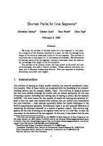
We assign a number i ≥ 1 to each camera. The relative pose between two cameras i and j is denoted by (Ri j , t i j ). It is defined such that it maps a 3D point pi from the ith camera coordinate system to the jth one as follows: p j = Ri j pi + t i j . The absolute poses (transforming points from world coordinates to kth camera coordinates) are denoted by (Rk , t k ). Note that relative poses have a double subscript, while absolute poses have a single one. When estimating relative poses from images only, the scale of t i j cannot be determined. We emphasize unknown scale by a star: t ∗i j . Relative pose estimation will be treated in section 3. A multi camera system together with the set of all known relative poses can be represented by the camera dependency graph [8] GR , which is also known as the image connectivity graph [17]: each camera is a vertex and camera i is connected to camera j iff the relative pose (Ri j , t ∗i j ) is known. An example is given in Figure 1. Note that edges are directed to distinguish (Ri j , t ∗i j ) from (R ji , t ∗ji ). As relative poses can be easily inverted, however, all edges will be treated as bidirectional. We will denote the sets of vertices and edges of any graph G by V(G) and E(G). 2.2
Calibration Task From Relative Poses
We assume known relative poses up to scale (Ri j , t ∗i j ) and seek to compute absolute poses (Rk , t k ) expressed in an arbitrary (but common) world coordinate system up to
An Efficient Shortest Triangle Paths Algorithm for Multi Camera Calibration GC
2
GR 1
GT
2 16
1
4
4
8
123
1
0 234
123
21 3
1
0 0
2 3
0 0
10 5
0
26 4
1
0
234
21 2 26 21 26 3
GP
4
2
0 0 0 3 0
123
10 5
21 21 21 12
13
3
4
0 234
26 26 26 23
24
43
inria-00325327, version 1 - 28 Sep 2008
Fig. 1. From left to right: a camera dependency graph GR with four cameras and five known relative poses, the associated triangle graph GT , the camera-to-camera triangle graph GC , and the relative-pose-to-camera triangle graph GP .
only one common unknown scale factor. More precisely, calibration is possible up to one 3D similarity transformation per triangle connected component (see Definition 1) in the camera dependency graph [18]. We will assume a triangle connected camera dependency graph. Otherwise, the algorithms can be applied to each component separately. 2.3
Calibration via Triangulation
A triangle in GR consists of three cameras and three known relative poses. If one of the scales kt i j k is known (or fixed), the remaining two scales can be computed by triangulation [10]. By treating one triangle after the other such that all consecutive triangles have a common edge, all scales can be computed up to one common unknown scale parameter. A basic calibration algorithm based on relative poses can be formulated nicely by using the triangle graph GT , which is defined as follows: each triangle in GR becomes a vertex in GT , two such vertices are connected in both directions iff the two triangles have a common edge in GR . An example is given in Figure 1. Once the scales have been estimated, the absolute poses can be extracted from the relative poses based on the following two equations: R j = Ri j Ri and t j = Ri j t i + t i j . These steps can be integrated into the following relative pose calibration algorithm: First choose a starting triangle (i, j, k) ∈ V(GT ) and set kt i j k = 1, Ri = I, and t i = 0. Then traverse GT , e.g. via breadth first search (BFS). When visiting a triangle, estimate the missing scale factors via triangulation and extract the missing absolute poses.
3
Selection of Relative Poses
In the relative pose calibration algorithm, the traversal order is unspecified. Furthermore, in case of a dense camera dependency graph, only a rather small subset of triangles has to be visited in order to calibrate all cameras. Thus, the traversal order corresponds to a selection of triangles and thus relative poses. As the quality of the relative pose estimates varies between camera pairs, a more sophisticated traversal is desirable. As in previous work [15], we calibrate along shortest triangle paths in the camera dependency graph adopting the approach of Vergés-Llahí, Moldovan and Wada [8]. A formal definition of shortest triangle paths follows in Section 3.1. We have suggested three different uncertainty measures on relative poses based on a paper by Engels and
4
Ferid Bajramovic and Joachim Denzler
Nistér [16]: the local information, the global entropy and an intermediate measure, which we called smoothed information. Roughly speaking, relative pose are computed using an extension of RANSAC [14] based on the five point algorithm [11]. During the iterations, additional information is collected to compute the uncertainty measures. We choose one of these measures to assign an uncertainty w(e) to each edge e ∈ GR . These values can also be interpreted as edge weights w : E(GR ) → [0, ∞[. Furthermore, we have shown that our measures are well suited for a theoretically sound formulation of relative pose selection as a discrete optimization problem. This provides a theoretical justification for the shortest triangle paths approach.
inria-00325327, version 1 - 28 Sep 2008
3.1
Criterion for the Selection of Relative Poses
Calibrating the pose of a camera j relative to a reference camera i involves a sequence of triangles in GR such that each two consecutive triangles have a common edge. We call such a sequence a triangle path from camera i to camera j which we formally define as: P = (i, T1 , . . . , Tn , j), where Tk ⊆ GR is a triangle for all 1 ≤ k ≤ n, E(Tk )∩E(Tk+1 ) , ∅ for all 1 ≤ k < n, i ∈ V(T1 ), and j ∈ V(Tn ). As pointed out before, there are often several alternative triangle paths P. Based on the uncertainty measures defined above, we assign a total uncertainty to each triangle path P and choose one with minimum total uncertainty. We model the total uncertainty as w1 (P) = def
X
w(t ∗i, j ),
(i, j)∈E1 (P)
where
E1 (P) = def
n [
E(Tk )
(1)
k=1
denotes the set of all edges in P. For our three uncertainty measures, this model is theoretically sound [15]. The total uncertainty w1 (P) can be interpreted as the length of the triangle path P (see also Definition 3). Using this approach to calibrate a whole multi camera system involves shortest triangle paths from i to all other cameras. Note, however, that the subgraph Si ⊆ GR induced by all these triangle paths (i.e. the union of all triangles in all paths) has to be triangle connected for reconstructing consistent scales for all t ∗i j . Definition 1 A subgraph G0R of GR is called triangle connected iff for all cameras i, j ∈ V(G0R ) there is a triangle path from i to j in G0R . A triangle connected component of GR is a maximal triangle connected subgraph of GR . While the common reference camera only guarantees that Si is connected, using a common reference edge r ∈ E(GR ) instead actually guarantees that Sr is triangle connected. Hence, we use shortest triangle paths from a common relative pose to all cameras. We choose the reference relative pose r ∈ E(GR ) with minimum total uncertainty P w(Sr ) = e∈E(Sr ) w(e). In other words, we use the shortest triangle connected shortest triangle paths subgraph. This extends the shortest triangle paths approach of VergésLlahí, Moldovan and Wada [8]. 3.2
Computing Shortest Triangle Paths
In this section, we present an efficient algorithm for our selection criterion, which is a shortest triangle paths problem. Note that Vergés-Llahí, Moldovan and Wada [8] men-
An Efficient Shortest Triangle Paths Algorithm for Multi Camera Calibration
5
inria-00325327, version 1 - 28 Sep 2008
tion the need for an efficient shortest triangle paths algorithm, but do not actually present one. This gap is filled by our algorithm [15]. In this paper, we prove its correctness. Note also that the shortest (ordinary) paths algorithm in the related paper by Martinec and Pajdla [13] solves a different problem. Definition 2 The camera-to-camera triangle graph GC is an extension of the triangle graph GT . A vertex in GT is called triangle vertex. Additionally, there is an entry vertex and an exit vertex for each camera. There is an edge from an entry vertex to a triangle vertex iff the respective camera is in the respective triangle. There is an edge from a triangle vertex to an exit vertex iff the respective camera is in the respective triangle. Edge weights wC are defined as follows: P w(e) if k is an entry vertex e∈E(Tl ) (2) wC (k, l) = 0 if l is an exit vertex Pe∈E(T )\E(T ) w(e) if k, l are triangle vertices l k Figure 1 shows an example of a camera-to-camera triangle graph. Triangle paths PR from a camera i to a camera j in GR directly correspond to ordinary paths PC in GC from an entry vertex to an exit vertex. We call such a path PC an entry-exit path. Also, shortest entry-exit paths in GC directly correspond to triangle paths from i to j with minimum total uncertainty in GR . Details and a proof will follow in Section 4. Hence, we can use a standard shortest paths algorithm (e.g. Dijkstra) on GC to compute shortest triangle paths in GR . As argued in the previous section, in order to calibrate all cameras, we want to compute shortest triangle paths from a reference relative pose r to all cameras. For that task, we construct a modification of GC , which we call relative-pose-to-camera triangle graph GP : instead of an entry vertex for each camera, there is now an entry vertex for each relative pose and there is an edge from an entry vertex to a triangle vertex iff the respective camera pair is in the respective triangle in GR . The edge weights are defined identically as in equation (2). Figure 1 shows an example. Triangle paths from a relative pose r to a camera i in GR directly correspond to entryexit paths in GP . Also, shortest entry-exit paths in GC directly correspond to shortest triangle paths from r to j in GR (see Section 4). The shortest paths tree from the entry vertex of a reference relative pose r to all exit vertices in GP (not to all vertices in the graph!) induces a triangle connected subgraph Sr in GR , which consists of shortest triangle paths from r to all cameras. We choose r such that the total uncertainty w(Sr ) = P e∈E(Sr ) w(e) is minimal by applying Dijkstra to all entry vertices r.
4
Proof
In this section, we will prove that shortest triangle paths correspond to shortest paths in GC and GP respectively. This requires a more graph theoretical point a view. Furthermore, we will be using multisets, i.e. sets which allow for duplicate elements. We will use standard set notation with an M subscript. Example: {a, b, b, b, b}M \M {b, b}M =M {a, b, b}M . We use the notation U(A) to denote the set containing all elements in a multiset A, i.e. with duplicate elements removed.
6
Ferid Bajramovic and Joachim Denzler
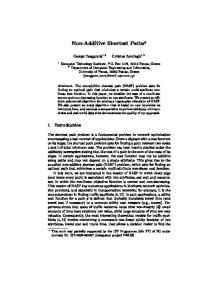
Definition 3 (alternative length of a triangle path) Let P = (i, T1 , . . . , Tn , j) be a triangle path from a camera i to a camera j. The multiset E2 (P) consists of all edges in def all triangles without adding common edges in consecutive triangles twice: E2 (P) = Fn E(T1 ) t i=2 E(Ti ) \ E(Ti−1 ), where t denotes the multiset union operation. This leads P to the alternative definition of the length of a triangle path: w2 (P) = e∈M E2 (P) w(e). In equation (1), we have already defined the length w1 (P). An example for the difference between w1 (P) and w2 (P) is shown in Figure 2: The edge e is in E2 (P) at least once more than in E1 (P).
inria-00325327, version 1 - 28 Sep 2008
Definition 4 (shortest triangle path) Let i and j be two cameras and k ∈ {1, 2}. A triangle path P from i to j is called a wk shortest triangle path from i to j iff all triangle paths P0 from i to j are at least as long: wk (P) ≤ wk (P0 ). Lemma 5 Let PR be a triangle path from camera i to camera j and let PC be the respective entry-exit path in GC . Then w2 (PR ) = wC (PC ), where wC (PC ) denotes the classical path length in GC . Proof: Both, w2 (PR ) and wC (PC ), are ultimately sums of edge weights in GR . By construction, both terms sum over the same multiset of edges. � Corollary 6 Shortest entry-exit paths in GC bijectively correspond to w2 shortest triangle paths from a camera i to a camera j in GR . In case of the definition w1 for the length of a triangle path, it seems to be impossible to construct equally suitable weights in GC . Nevertheless, the weights wC can be used to compute shortest triangle paths with respect to w1 triangle path lengths. Theorem 7 Let P be a triangle path from a camera i to a camera j. Let w(e) > 0 for all e ∈ E(GR ). P is a w1 shortest triangle path iff P is a w2 shortest triangle path. The proof will be given at the end of this section. Due to Corollary 6 and Theorem 7, w1 shortest triangle paths from a camera i to a camera j can be computed as shortest paths in GC . The latter is a standard problem, which can be solved using e.g. the Dijkstra algorithm. The restriction w(e) > 0 for all e ∈ E(GR ) poses no problem as in practice the uncertainty will never be zero. In case of shortest triangle paths from a relative pose r to a camera j, we have the same situation: w1 shortest triangle paths from a relative pose r to a camera j can be computed as shortest entry-exit paths in GP . The same results and proofs apply after substituting “from a camera i” by “from a relative pose r”, “i” by “r”, “camera-tocamera” by “relative-pose-to-camera”, and “GC ” by “GP ”. Lemma 8 Let P be a triangle path. Then we have E1 (P) ⊆M E2 (P),
E1 (P) = U(E2 (P)),
and
w1 (P) ≤ w2 (P) .
(3)
Proof: The first two equations follow trivially from Definition 3. As all edge weights in GR are non-negative, the third equation follows from the first one. �
An Efficient Shortest Triangle Paths Algorithm for Multi Camera Calibration P
GR
GR
Tk e T l
P e
7
Fig. 2. Second case in the proof of Lemma 9. Left: general case, right: minimal case.
inria-00325327, version 1 - 28 Sep 2008
Lemma 9 Let P be a triangle path from a camera i to a camera j. Let w(e) > 0 for all edges e ∈ E(GR ). If w2 (P) > w1 (P), then there is a triangle path P0 from i to j with E2 (P0 ) $M E2 (P) and w2 (P0 ) < w2 (P). Proof: Let P be a triangle path from a camera i to a camera j with w2 (P) > w1 (P). As w2 (P) > w1 (P) and E1 (P) ⊆M E2 (P), we have E1 (P) $M E2 (P), i.e. there are duplicate elements in E2 (P). We will construct a path P0 from P which removes at least one duplicate element from E2 (P). Let P = (i, T1 , . . . , Tn , j) with n ≥ 1. Once we have E2 (P0 ) $M E2 (P), the inequality w2 (P0 ) < w2 (P) follows directly. There are two cases: 1. A triangle T ∗ appears in P more than once: There are k, l with 1 ≤ k < l ≤ n such that Tk = Tl = T ∗ . If l = k + 1, the lth triangle does not add any edges to E2 (P) (Definition 3) and can simply be removed. Hence, without loss of generality, we can assume l ≥ k + 2. Set P0 = (i, T1 , . . . , Tk , Tl+1 , . . . , Tn , j). P0 is a triangle path from i to j containing fewer triangles than P (there is one occurrence of T ∗ less in P0 than in P). As l ≥ k + 2, this implies E2 (P0 ) $M E2 (P). 2. No triangle appears twice in P: In this case, there are two non-consecutive triangles in P, which have a common edge e. I.e. there are k, l with 1 ≤ k < l − 1 ≤ n such that e ∈ E(Tk ) ∩ E(Tl ). Figure 2 visualizes this case. Set P0 = (i, T1 , . . . , Tk , Tl , . . . , Tn , j). The edge e is in E2 (P0 ) at least once less than in E2 (P). Thus E(P0 ) $M E(P). � Lemma 10 Let P be a triangle path from a camera i to a camera j. Let w(e) > 0 for all edges e ∈ E(GR ). If w2 (P) > w1 (P), then there is a triangle path P0 from i to j with E1 (P0 ) $ E1 (P) and w1 (P0 ) < w1 (P). Proof: Let P = (i, T1 , . . . , Tn , j), n ≥ 1 be a triangle path from a camera i to a camera j with w2 (P) > w1 (P). Construct a path P1 as in the proof of Lemma 9. P1 removes one occurrence of an edge e from E2 (P). There are two possibilities: 1. There is an edge e ∈ E2 (P) \M E2 (P1 ) with e < E2 (P1 ): As E1 (P1 ) ⊆M E2 (P1 ), we have e < E1 (P1 ) and thus E1 (P1 ) $ E1 (P) and w1 (P1 ) < w1 (P). 2. Otherwise, there are again two possible cases: (a) E1 (P1 ) $M E2 (P1 ): Then w1 (P1 ) < w2 (P1 ) and we can recursively apply the construction in this proof to P1 instead of P. This leads to a sequence of triangle paths (P, P1 , . . .). Each step removes at least one occurrence of an edge from E2 (P... ). As E2 (P) is finite, the sequence cannot be infinite and thus has to reach one of the other cases.
8
Ferid Bajramovic and Joachim Denzler P1 P
P P P1
e3 Tk Tl
T0 e1 e 2 Tk+1
e3
P1
GR
T
P
Tk
00
e2
Tl
P Tk+1
P1
T∗ e1
P1
inria-00325327, version 1 - 28 Sep 2008
Fig. 3. Left: case 2(b)i in the proof of Lemma 10, right: case 2(b)ii.
(b) E1 (P1 ) =M E2 (P1 ): In this case, we have a closer look at P1 . There are k, l with l ≥ k + 2 such that P1 = (i, T1 , . . . , Tk , Tl , . . . , Tn , j). I.e. at least one triangle between k and l has been removed from P. i. E(Tk+1 )∩E(Tl ) = ∅: This case is depicted in Figure 3, left. Let {e1 , e2 , e3 } = E(Tk+1 ) with {e1 , e2 } = E(Tk+1 ) \ E(Tk ). As E1 (P1 ) =M E2 (P1 ), we know that E2 (P1 ) does not contain multiple elements. Thus Tk+1 cannot be in P1 (otherwise e3 would be in E(P1 ) twice). Hence there are triangles T 0 and T 00 in P1 with T 0 , T 00 such that e1 ∈ E(T 0 ) and e2 ∈ E(T 00 ). We can write P1 = (i, . . . , Tˆ 1 , . . . , Tˆ 2 , . . . , Tˆ 3 , . . . , j) with {Tˆ 1 , Tˆ 2 , Tˆ 3 } = {Tk , T 0 , T 00 }. Now set P2 = (i, . . . , Tˆ 1 , Tk+1 , Tˆ 3 , . . . , j). Then we have: E1 (P2 ) ⊆ E1 (P1 ), i.e. there are no new edges in E1 (P2 ) compared to E1 (P1 ), as E(Tk+1 ) = {e1 , e2 , e3 } ⊆ E1 (P1 ). Furthermore, (E(Tˆ 2 ) \ E(Tk+1 )) ∩ E1 (P2 ) = ∅, i.e. there are two edges less in E1 (P2 ) than in E1 (P1 ). Thus we have E1 (P2 ) $ E1 (P1 ) and w1 (P2 ) < w1 (P1 ) ≤ w1 (P). ii. E(Tk+1 ) ∩ E(Tl ) , ∅: This case is depicted in Figure 3, right. Let {e1 } = E(Tk+1 ) \ E(Tk ) \ E(Tl ). Then e1 ∈ E2 (P) \M E2 (P1 ), i.e. e1 is in E2 (P) more often than in E(P1 ), because Tk+1 has been removed from P to construct P1 . Combined with case 2, this implies e1 ∈ E2 (P1 ). As E1 (P1 ) = U(E2 (P1 )) (Lemma 8), this leads to e1 ∈ E1 (P1 ). Tk+1 is not in P1 . Otherwise each of the two edges in E(Tk+1 ) \ {e1 } would be in E2 (P1 ) twice, but E2 (P1 ) does not contain duplicates, as E1 (P1 ) =M E2 (P1 ) (case 2b). There is a triangle T ∗ , Tk+1 with e1 ∈ E(T ∗ ) in P1 , as e1 ∈ E1 (P1 ). A. T ∗ is in P1 after Tk and Tl , i.e. P1 = (i, . . . , Tk , Tl , . . . , T ∗ , . . . , j): In this case, set P2 = (i, . . . , Tk , Tk+1 , T ∗ , . . . , j). Then E1 (P2 ) ⊆ E1 (P1 ), i.e. there are no additional edges in P2 compared to P1 . Let {e2 } = E(Tl ) \ E(Tk ) \ E(Tk+1 ). We known that e2 is in E2 (P1 ) exactly once (as E1 (P1 ) =M E2 (P1 ) due to case 2b). Thus e2 < E2 (P2 ) and thus e2 < E1 (P2 ), as E1 (P2 ) ⊆M E2 (P2 ) (Lemma 8). We get E1 (P2 ) $ E1 (P1 ) and w1 (P2 ) < w1 (P1 ) ≤ w1 (P). B. T ∗ is in P1 before Tk and Tl , i.e. P1 = (i, . . . , T ∗ , . . . , Tk , Tl , . . . , j): In this case, set P2 = (i, . . . , T ∗ , Tk+1 , Tl , . . . , j). With an analog argumentation to the previous case (involving an edge e3 instead of e2 , Figure 3), we get E1 (P2 ) $ E1 (P1 ) and w1 (P2 ) < w1 (P1 ) ≤ w1 (P). �
An Efficient Shortest Triangle Paths Algorithm for Multi Camera Calibration
9
The previous lemmas roughly state that if the lengths w2 and w1 of a triangle path are not equal, there will be a shorter triangle path with respect to w2 , as well as a shorter triangle path with respect to w1 . Corollary 11 Let P be a triangle path from a camera i to a camera j. Let w(e) > 0 for all e ∈ E(GR ). If P is a w2 or w1 shortest triangle path, then w2 (P) = w1 (P).
inria-00325327, version 1 - 28 Sep 2008
Proof: Let PC be a w2 [w1 ] shortest triangle path from i to j. Thus, there cannot be a shorter triangle path. Due to Lemma 9 [Lemma 10], this implies w2 (P) ≤ w1 (P). Using Lemma 8, we known that w2 (P) ≥ w1 (P). Thus, w2 (P) = w1 (P). � Proof of Theorem 7: First part: Let P be a w1 shortest triangle path from i to j. Let P0 be any triangle path from i to j. Using Lemma 8, Definition 4, and Corollary 11 we have: w2 (P0 ) ≥ w1 (P0 ) ≥ w1 (P) = w2 (P). Thus P is a w2 shortest path. Second part: Let P be a w2 shortest triangle path from i to j. Let P0 be a w1 shortest triangle path from i to j. This implies w1 (P0 ) ≤ w1 (P). Using Corollary 11 twice, we get w2 (P0 ) = w1 (P0 ) ≤ w1 (P) = w2 (P) and thus w2 (P0 ) ≤ w2 (P). As P is a w2 shortest triangle path, we also have w2 (P) ≤ w2 (P0 ). Combining these inequalities, we get w2 (P) = w2 (P0 ) and thus w1 (P0 ) = w1 (P). As P0 is a w1 shortest path, P is also a w1 shortest path. �
5
Experiments
As a multi camera system can only be calibrated up to a 3D similarity transformation, we compute and apply an optimal transformation between the calibration result and the ground truth using a linear algorithm followed by nonlinear refinement. As an error measure for the calibration of a multi camera system in comparison to the ground truth, P we use the mean position error e = n1 i kRi t i − RG,i t G,i k2 , where the subscript G indicates ground truth. The ground truth calibration is normalized such that the distance of the first two cameras is one. This defines the scale of the error measure e. 5.1
Simulation
The simulation consists of ten (instead of six as in previous work [15]) virtual pinhole cameras (K, RG,i , t G,i ) with image size 640 × 480 and calibration matrix K = ((1500, 0, 320), (0, 1500, 240), (0, 0, 1))T . The scene consists of 100 random 3D points uniformly distributed in a cuboid. The cameras are placed in a circle above the points looking roughly towards the center of the cuboid such that all cameras can see all points. The height above the scene of every second camera is slightly increased to avoid planarity. The 3D points are projected into the cameras with subpixel precision. Noise is simulated by adding random values uniformly distributed in [−φ/2, φ/2] to all coordinates. We choose φ = 1 for all experiments. Outliers are simulated by replacing a certain fraction of the point correspondences of each camera pair by points uniformly distributed within the image areas. We perform experiments with the following amounts of outliers: 0%, 30%, 70%, and 80%. All experiments are repeated 50 times and the resulting mean position errors e are plotted in sorted order. This corresponds to computing all error quantiles. A good algorithm should, of course, have a low and flat error curve.
10
Ferid Bajramovic and Joachim Denzler e
e
BFS, 30% selection: smooth, 30% BFS, 70% selection: smooth, 70% BFS, 80% selection: smooth, 80%
0.8
0.8
0.6
0.6
0.4
0.4
0.2
0.2
0
0 0
inria-00325327, version 1 - 28 Sep 2008
BFS, 0% selection: smooth, 0% BFS, 30% selection: smooth, 30% BFS, 70% selection: smooth, 70% selection: smooth, 80%
0.1
0.2
0.3
0.4
0.5
0.6
0.7
quantile
0
0.1
0.2
0.3
0.4
0.5
0.6
0.7
quantile
Fig. 4. Comparison of the BFS traversal with our uncertainty based selection of relative poses using the smoothed information measure and the Blake-Zisserman distribution. The percent values denote the portion of outliers. The plot shows sorted mean position error values e (quantiles). Left: first experiment, right: second experiment.
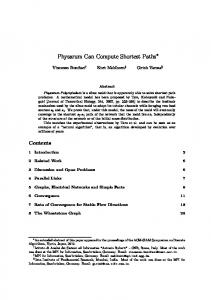
Fig. 5. Setup of the real experiment. Left: the multi camera system observing the pattern for the Zhang calibration, right: the scene (image from the sixth camera).
We perform the following two experiments. In the first one, we increase the portion of outliers of the camera pairs (i, i + 1) for 1 ≤ i ≤ 9 such that only half of the inliers remain (e.g. instead of 30%, these camera pairs have 65% outliers). In the second experiment, the noise level of these camera pairs is increased from 1 to 5 without changing the portion of outliers. We compare the BFS traversal to our selection criterion using the Blake-Zisserman distribution and the smoothed information measure [15]. Figure 4 clearly shows that our selection criterion greatly improves the calibration results in both situations. This shows that in both cases the camera pairs with contaminated data can be identified by the smoothed information measure and that the selection mechanism is able to avoid them. Overall, the simulation experiments show that our relative pose selection criterion greatly improves calibration results in case of some camera pairs with additional outliers or additional noise. 5.2
Real Data
The experiment on real data consists of two AVT Marlin monochrome cameras and six AVT Pike color cameras observing a scene, as depicted is Figure 5. We estimate the intrinsic camera parameters using Zhang’s [1] calibration pattern based method. To
An Efficient Shortest Triangle Paths Algorithm for Multi Camera Calibration e
11
BFS selection: information selection: smoothed information selection: entropy
0.8
0.6
0.4
0.2
0 0
0.1
0.2
0.3
0.4
0.5
0.6
0.7
quantile
inria-00325327, version 1 - 28 Sep 2008
Fig. 6. Experiment on real data. Left: mean position error quantile results for BFS as well as our selection criterion. Right: a visualization of a calibration result (cyan / light gray) with a mean position error e ≈ 0.03 compared to a Zhang calibration (blue / dark gray). Even though the two calibrations are not identical, the structure of the multi camera system is well reconstructed.
be able to evaluate our calibration results, we use Zhang’s method also to compute a “ground truth” for the extrinsic calibration. Note that this “ground truth” is not free of errors, but still provides a reasonable comparison. As input for our calibration, we extract 100 point correspondences in each image pair using SIFT [19]. Figure 6 contains the results for three different uncertainty measures using the Blake-Zisserman distribution [15]. Our selection criterion using the smoothed information measure or the entropy measure provides greatly improved calibration results compared to the BFS traversal. This demonstrates that our method is actually beneficial in practical situations, where the quality of the correspondences between camera pairs cannot be strictly devided into “good” and “bad”.
6
Conclusions
In the context of calibrating a multi camera system via pairwise relative poses, we formulated the selection of relative poses as a graph based discrete optimization problem using an uncertainty measure as edge weights. We presented an efficient algorithm for that problem and a mathematically rigorous proof of its correctness. In the simulation experiments, we showed that our selection criterion is able to greatly improve calibration results by avoiding bad relative poses caused by an increased outlier portion or increased noise. In experiments on real data, we demonstrated that calibration results are actually improved in a practical situation.
References 1. Zhang, Z.: A Flexible New Technique for Camera Calibration. IEEE Transactions on Pattern Analysis and Machine Intelligence (TPAMI) 22 (2000) 1330–1334 2. Kitahara, I., Saito, H., Akimichi, S., Ono, T., Ohta, Y., Kanade, T.: Large-scale Virtualized Reality. In: Proceedings of the IEEE Conference on Computer Vision and Pattern Recognition (CVPR), Technical Sketches. (2001)
inria-00325327, version 1 - 28 Sep 2008
12
Ferid Bajramovic and Joachim Denzler
3. Baker, P., Aloimonos, Y.: Complete Calibration of a Multi-camera Network. In: Proceedings of the IEEE Workshop on Omnidirectional Vision (OMNIVIS). (2000) 134–144 4. Svoboda, T., Martinec, D., Pajdla, T.: A Convenient Multi-Camera Self-Calibration for Virtual Environments. PRESENCE: Teleoperators and Virtual Environments 14 (2005) 407–422 5. Chen, X., Davis, J., Slusallek, P.: Wide Area Camera Calibration Using Virtual Calibration Objects. In: Proceedings of the IEEE Conference on Computer Vision and Pattern Recognition (CVPR). Volume 2. (2000) 2520–2527 6. Barreto, J.P., Daniilidis, K.: Wide Area Multiple Camera Calibration and Estimation of Radial Distortion. In: Proceedings of the IEEE Workshop on Omnidirectional Vision (OMNIVIS). (2004) 7. Martinec, D., Pajdla, T.: Robust Rotation and Translation Estimation in Multiview Reconstruction. In: Proceedings of the IEEE Conference on Computer Vision and Pattern Recognition (CVPR). (2007) 1–8 8. Vergés-Llahí, J., Moldovan, D., Wada, T.: A new reliability measure for essential matrices suitable in multiple view calibration. In: VISAPP 2008: Proceedings of the Third International Conference on Computer Vision Theory and Applications. Volume 1. (2008) 114–121 9. Hörster, E., Lienhart, R.: Calibrating and optimizing poses of visual sensors in distributed platforms. ACM Multimedia System Journal, Special Issue on Multimedia Surveillance System 12 (2006) 195–210 10. Hartley, R., Zisserman, A.: Multiple View Geometry in Computer Vision. 2nd edn. Cambridge University Press (2003) 11. Stewénius, H., Engels, C., Nistér, D.: Recent Developments on Direct Relative Orientation. ISPRS Journal of Photogrammetry and Remote Sensing 60 (2006) 284–294 12. Brückner, M., Bajramovic, F., Denzler, J.: Experimental Evaluation of Relative Pose Estimation Algorithms. In: VISAPP 2008: Proceedings of the Third International Conference on Computer Vision Theory and Applications. Volume 2. (2008) 431–438 13. Martinec, D., Pajdla, T.: 3D Reconstruction by Gluing Pair-Wise Euclidean Reconstructions, or "How to Achieve a Good Reconstruction from Bad Images". In: 3DPVT ’06: Proceedings of the Third International Symposium on 3D Data Processing, Visualization, and Transmission (3DPVT’06). (2006) 25–32 14. Fischler, M.A., Bolles, R.C.: Random sample consensus: a paradigm for model fitting with applications to image analysis and automated cartography. Communications of the ACM 24 (1981) 381–395 15. Bajramovic, F., Denzler, J.: Global Uncertainty-based Selection of Relative Poses for Multi Camera Calibration. In: Proceedings of the British Machine Vision Conference (BMVC). (2008) to appear 16. Engels, C., Nistér, D.: Global uncertainty in epipolar geometry via fully and partially datadriven sampling. In: ISPRS Workshop BenCOS: Towards Benchmarking Automated Calibration, Orientation and Surface Reconstruction from Images. (2005) 17–22 17. Snavely, N., Seitz, S., Szeliski, R.: Modeling the World from Internet Photo Collections. International Journal of Computer Vision (IJCV) (to appear) (2008) 18. Mantzel, W.E., Choi, H., Baraniuk, R.G.: Distributed Camera Network Localization. In: Proceedings of the 38th Asilomar Conference on Signals, Systems and Computers. Volume 2. (2004) 1381–1386 19. Lowe, D.G.: Distinctive Image Features from Scale-Invariant Keypoints. International Journal of Computer Vision (IJCV) 60 (2004) 91–110