We propose a new algorithm for a classical problem in plane computational geometry: computing a short- est path between two points in the presence of polyg-.
Efficient Computation of Euclidean Shortest Paths in the Plane (Extended Abstract)
John Hershberger*
Subhash Surit
Abstract
years of continued efforts, an optimal, linear-time algorithm is now known for computing a shortest path in a simple polygon [9, lo]. The general case of multiple obstacles, however, has proved to be substantially more difficult. There have been two fundamentally different approaches t o the problem-the visibility graph method and the shortest path map method. The visibility graph method is based on constructing a graph whose nodes are the vertices of the obstacles and whose edges are pairs of mutually visible vertices. The shortest path between two vertices can be found by running any Dijkstra-type algorithm on this graph [l, 6, 71. This approach fueled intense research on computing visibility graphs, culminating in an optimal O(n1ogn E ) time algorithm by Ghosh and Mount [8], where E is the number of edges in the graph. Unfortunately, the visibility graph can have s2(n2)edges in the worst case, and so any shortest path algorithm that depends on an explicit construction of the visibility graph will have a similar worst-case running time [2, 3, 11, 18, 201. A “holy grail” of this approach is to build and search only the portion of the visibility graph that is relevant to the shortest path computation, but no noteworthy progress has been made on that front. The second approach tries to solve a more general problem: build a shortest path map of the plane with respect to a fixed point s so that all points of a region have the same vertex sequence in their shortest path to s. This map, therefore, encodes the shortest paths from s to all points in the plane. This approach seems inherently more geometric than the graph-theoretic method based on visibility graphs. Nevertheless, most algorithms using this approach also have s2(n2)worst-case running times-however , their running times typically have the form O ( n C g ( n ) ) ,where IC is the number of obstacles and g(n) is a sublinear function, such as the poly-logarithm [ll, 13, 191. Thus, for a small number of obstacles, these bounds approach the time complexity for a single obstacle. Very recently, Mitchell has published an algorithm for computing a shortest path map + ‘ ) and space [14]; his algothat runs in O ( T Z ~ / ~time
We propose a new algorithm for a classical problem in plane computational geometry: computing a shortest path between two points in the presence of polygonal obstacles. Our algorithm runs in worst-case time O ( n l o g 2 n ) and requires O(n1ogn) space, where n is the total number of vertices in the obstacle polygons. Our algorithm actually computes a planar map that encodes shortest paths from a fixed source point to all other points of t h e plane; the map can be used to answer single-source shortest path queries in O(1og n ) time. The time complexity of our algorithm is a significant improvement over all previous results known for the shortest path problem.
1 1.1
+
Introduction The background and our result
The Euclidean shortest path problem is one of the oldest and best-known problems in computational geometry. Given a planar set of polygonal obstacles with disjoint interiors, the problem is t o compute a shortest path between two points avoiding all the obstacles. Due t o its simple formulation and obvious applications in routing and robotics, the problem has drawn the attention of many researchers in computational geometry; we mention only a few papers most relevant to our work [5, 9, 10, 12, 13, 14, 201. The problem of computing shortest paths in the presence of a single obstacle has received special attention, due t o its applications in various geometric problems involving a simple polygon [5, 9, 10, 121. The roles of the free space and obstacle space have been reversed traditionally in this special case: the interior of the polygon represents the free space and the boundary of the polygon represents an impenetrable obstacle. After several *Research supported in part by DEC Systems Research Center. Current email address: j ohnhof lamingo. stanf ord. edu. tBellcore, 445 South Street, Morristown, N J 07960
508
0272-542W3803.00 0 1993 IEEE
Page 1
rithm uses some advanced range searching data structures to locate the vertices of the shortest path map.’ The only lower bound known for the shortest path problem is O ( n log n ) in the algebraic computation tree model, and so there remains a relatively large gap between the known upper and lower bounds on this problem. Nevertheless, there has been a general belief in the computational geometry community that an almostlinear-time algorithm must be achievable. In this paper, we come close to matching the lower bound, and present an O ( n log’ n ) time algorithm for computing shortest paths in the presence of polygonal obstacles; n denotes the total number of vertices in all the obstacle polygons. Our algorithm takes the shortest path map approach and builds a subdivision of the plane, which after additional linear-time preprocessing can be used to answer shortest path queries from a fixed point. A key idea in our algorithm is a special, quad-treestyle subdivision of the plane with respect to an arbitrary set of points P . This subdivision, called a conforming subdivision, divides the plane into a linear number of cells using horizontal and vertical edges so that the following critical condition holds: each point of P lies in a separate cell, and there are O(1) cells within distance le1 of a subdivision edge e. Though such a subdivision can also be obtained using a quad-tree construction of Bern et al. [4],their method gives a subdivision of size O ( nlog A), where A is the aspect ratio of the Delaunay triangulation of P . In fact, R(n1ogA) is also a lower bound in the worst-case for the quad-tree construction of [4].Our subdivision achieves linear upper bound by enforcing weaker condition: for instance, cells in our subdivision may be nonconvex and the subdivision itself may not be connected. Nevertheless, our conforming subdivision appears to be a useful tool and is likely to have other applications.
1.2
cessing events that change its topology. These events fall into two categories: wavefront-wavefront collisions and wavefront-obstacle collisions. The ability to process these events efficiently is the key to a fast algorithm for the shortest path problem. Detecting and processing these events quickly, however, appears to be quite difficult, and except for the recent result of Mitchell [14],all previous algorithms employing the continuous Dijkstra method have led only to a O ( n 2 )worst-case bound. We introduce two new ideas to speed up the implementation of the wavefront propagation method: a quad-tree-style subdivision of the plane, and an approximate wavefront. Our first idea is to recognize that advancing a wavefront from event to event can be difficult without a sufficiently well-behaved subdivision of the plane to guide the propagation. We build a special subdivision of size O ( n ) on the vertices of the obstacles, temporarily ignoring the line segments between them. Each cell of this subdivision, called a conforming subdivision, has a constant number of straight line edges, contains a t most one obstacle vertex, and satisfies the following crucial property: for any edge e of the subdivision, there are O(1) cells within distance (el from e. We then insert the obstacle line segments into the subdivision, but maintain both the linear size of the subdivision as well as its conforming property-except now only a non-obstacle edge e has the property that there are O(1) cells within shortest path distance le( of the edge. These cells form the units of our propagation algorithm: in each step, we advance the wavefront through one cell. Since each cell has constant descriptive complexity, we are able to do the propagation in a cell efficientlv. Inside a cell, a wavefront-obstacle event is relatively easy to handle. However, a wavefront-wavefront event is more complex. There are two types of wavefrontwavefront events, depending on whether or not the colliding wavelets are neighbors in the wavefront. The collision of neighboring wavelets occurs when a wavelet is engulfed by the expanding wavelets of its two neighbors. This event is easy t o detect and process. The collisions between non-neighboring wavelets, however, are more troublesome, and to process them we introduce our second idea: the approximate wavefront. When trying to propagate the wavefront across a boundary edge of a cell, we give up the idea of computing the wavefront exactly. Instead. we content ourselves with two separate wavefronts, approaching the edge from opposite sides. Each of these wavefronts is an approxzmate wavefront. The approximate wavefronts represent the wavefronts that would hit the edge from the two sides if the edge were replaced by an opaque segment. We use timers to make conservative estimates of the wavefront’s state, and discard any parts of the wave-
An overview of the algorithm
We use a technique dubbed the continuous Dajkstra method in the literature [13, 14, 151. It simulates the expansion of a wavefront from a point source in the presence of polygonal obstacles. The wavefront at time t consists of all points of the plane whose shortest-path distance to the source is t. The boundary of the wavefront is a set of cycles, each composed of a sequence of circular arcs. Each arc. called a wavelet, is generated by an obstacle vertex already covered by the wavefront: the vertex is called the generator of its wavelet. The meeting point between two adjacent wavelets sweeps along a bisector curve, which is either a straight line or a hyperbola. Simulating the wavefront requires pro’ A version of Mitchell’s result with improved time and space complexity is in preparation (Mitchell, personal communication).
509
front arriving at a cell boundary after a timer a t that boundary edge goes off. A critical task of these timers is to ensure that the wavefront-wavefront collisions of the true shortest path map are detected during approximate wavefront propagation in a small neighborhood of their actual location. The algorithm propagates the approximate wavefront, remembering the wavefront-wavefront collisions and updating the wavefront so that it has enough information t o act as an approximate wavefront at any time. At the end of the propagation phase, we collect all the collision information, then use Voronoi diagram techniques in each cell t o compute the collision events in that cell precisely. The collisions determine the edges of the final shortest path map, which we build by a standard plane sweep. This extended abstract contains five sections. Section 2 describes our conforming subdivision of the free space; Section 3 describes the key shortest path properties used by our algorithm; and Section 4 describes our algorithm for computing a shortest path map. Finally, in Section 5 we discuss data structures and finer details of our algorithm.
2
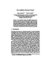
2. the total complexity of all the cells in C ( e ) is O(1), and 3. if f is an edge on the boundary of the union U ( e ) , then the Euclidean distance between e and f is at least (14, If I). Let V denote the set of vertices of the obstacle polygons. A subdivision S is called a conforming subdivision for V if 1. each point of V lies in a separate cell of S, and 2. each internal (non-boundary) edge of S is wellcovered, and 3. the well-covering region of every internal edge of S contains a t most one vertex of V .
Our conforming subdivision S is similar t o a quadtree in that all its edges are horizontal or vertical. However, the cells of S may be nonconvex and the subdivision itself may be disconnected. Each cell is reasonably well-behaved, though-there is at most one hole per cell. More specifically, each cell is either a square or a square-annulus (a square minus a square); the boundaries of these squares, however, may be subdivided into a constant number of edges. Each square-annulus also satisfies a minimum clearance property: the minimum width of the annulus is a t least one quarter of the side length of the outer square. Due to lack of space, we omit the construction details of this subdivision, and simply state the main result.
A conforming subdivision of the free space
The input t o our shortest path problem is a family of polygonal obstacles 0 = { 0 1 , 0 2 , . . . ,O k } . Each obstacle is a simple polygon and the interiors of any two obstacles are disjoint. The total number of vertices in all the obstacles is denoted n . The plane minus the interiors of all obstacle polygons is called the free space, and a path is called legal if it lies entirely in the free space-that is, the path is disjoint from the interiors of all obstacle polygons in the family 0. Given two points in the plane, a Euclidean shortest path between them is a legal path of minimum total length. A key ingredient of our shortest path algorithm is a special subdivision of the plane into cells of constant descriptive complexity. We construct this subdivision in two steps: the first step builds a subdivision by considering just the vertices of the obstacle polygons, and then the second step inserts the obstacle edges into the subdivision. Let us first describe the subdivision for the set of obstacle vertices. Our subdivision is inspired by quad-trees, though it is best implemented bottom-up. A crucial property of our subdivision is well-covering of its internal edges. Given a straight-line subdivision S of the plane, an edge e E S is said to be well-covered if the following three conditions hold:
Figure 1: Part of a conforming subdivision of a set of points. The shaded region is the union of cells U ( e ) forming a well-covering of e.
Theorem 2.1 Every set of n points in the plane admits a conforming subdivision of O ( n ) sue. Such a svbdivision can be computed i n time O ( nlog n ) . In the second step of our construction. we modify the conforming subdivision of V to accommodate the edges of the obstacles. In the modified subdivision, there are two types of edges: the artificial edges introduced by the
1. there exists a set of cells C ( e ) S such that e lies in the interior of their union U ( e ) = { c I c E C ( e ) } ,
510
3
subdivision construction and the obstacle edges. To distinguish between them, we call the former transparent edges and the latter opaque edges; a wavefront can pass through the transparent edges, but it is blocked by the opaque edges. We require that all transparent edges be well-covered in the conforming subdivision for the obstacles. In particular, condition (3) in the definition of well-covering is modified t o the following:
Geometric properties shortest paths
of
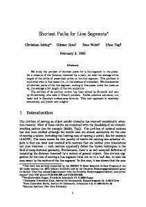
In this section, we establish the key geometric properties of shortest paths used by our algorithm. Euclidean shortest paths need not be unique-for instance, every obstacle polygon 0, has at least one point on its boundary reached by two shortest paths; the two shortest paths together form a cycle enclosing the polygon. We use the notation w(p,q ) to denote the set of shortest paths connecting two points p and q. The length of any path in w ( p , q ) is the shortest path distance between p and q, denoted d ( p , q ) ; we occasionally use d ( X , Y ) to refer to the shortest path distance between two sets of points X and Y . (Clearly, if one or both points lie inside an obstacle, there is no legal path between them and their shortest path distance is assumed to be infinite.) If the shortest path between p and q is the line segment jZj,then p and q are said t o be mutually visible. We consider the problem of computing shortest paths from a fixed point s to all points of the free space. For an arbitrary point p , we define its predecessor to be the vertex (or vertices) adjacent to p in w ( p , s ) . A predecessor of p is necessarily visible from p . (If p and s are mutually visible, the sole predecessor of p is s.) We define the weight of a vertex t o be its shortest path distance to s. For an arbitrary point p in free space, we define its weighted distance t o a visible vertex U as I@l+ d(u, s); i.e., the weighted distance equals the straight-line distance from p to U , plus the shortest path distance from 'U. to s. The shortest path map of a particular source point s, denoted S P M ( s ) , is a subdivision of the plane into regions such that all the points in one region have the same, unique predecessor. Points on region boundaries have multiple predecessors. Figure 3 shows an example of a shortest path map.
3'. Let e and f be two transparent edges of S such that f lies on the boundary of the union U ( e ) . Then the shortest path distance between e and f is at least m= (14If 1).
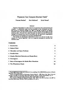
Let us describe briefly how to modify a conforming subdivision for V into a similar one for U. Let S be a conforming subdivision for V , the vertices of the obstacles. S has O ( n ) vertices, edges, and faces (cells), and each face is either a square or a squareannulus. Overlaying the obstacle edges on top of S cuts the plane into O ( n 2 )cells. From this new subdivision, we essentially discard any faces that don't have an interesting feature, namely, an obstacle vertex or a vertex of S. More specifically, for every vertex of U and for every vertex of S, keep the cells to which the vertex is incident (at most four cells per S vertex and one cell per obstacle vertex). Delete every edge fragment of S not on the boundary of one of these kept cells. In the resulting subdivision, all cells are convex except those containing an obstacle vertex or those derived from a squareannulus. Since there are altogether O(n) vertices, by planarity the number of cells is also O(n). We show that each internal non-obstacle edge of this subdivision is well-covered. We call this subdivision a conforming subdivision of the free space.
Figure 2: Part of a conforming subdivision of a set of obstacles. The shaded region is the union of cells U ( e ) forming a well-covering of e.
S
Theorem 2.2 Everg family of disjoint simple polygons with a total of n vertices admits a Conforming subdivision of total size O ( n ) . W e can build such a subdivision i n time O ( n log n ) .
Figure 3: S P M ( s ) and a wavefront sweeping it.
511
Lemma 3.1 The subdivision S P M ( s ) has O ( n ) vertices, edges, and faces. Each edge is a segment of a line or a hyperbola.
gates only across transparent edges; it dies upon meeting an opaque edge, and that processing is much simpler. Instead of using the exact wavefront. we content ourselves with approximate wavefronts at a transparent edge. Specifically, a t each transparent edge, we compute two approximate wavefronts, passing through the edge in opposite directions. An approximate wavefront represents the wavefront reaching an edge from one side of the edge only. We can think of an approximate wavefront as labeling each point p on the edge with the time a t which the approximate wavefront reaches p . The true distance d ( p , s) is the minimum of the two labels.
A bisector is an edge of the shortest path map S P M ( s ) with two predecessors-it is an arc of the hyperbola generated by two weighted vertices.
Lemma 3.2 Let U and v be two obstacle vertices, lying on the same side of a line e, that generate a bisector. The line e intersects the bisector at most once i n either half-plane defined b y the line supporting G.
An approximate wavefront at an edge e is represented as a sequence of polygon vertices weighted with their
Our construction of S P M ( s ) uses the continuous Dijkstru paradigm [13, 14, 161, which computes shortest paths by simulating a unit-speed wavefront expanding outward from the source s. During the simulation, the algorithm works with portions of the wavefront generated by subsets of the obstacle vertices. Each vertex v in such a subset H has a weight W ( V ) = d ( v , s ) . The relevant wavefront a t time t is the union of disks centered at vertices in H , where the disk centered a t v has radius t - ~ ( v ) A . key operation performed by our algorithm is to compute the first point of contact between an expanding wavefront and a line. We use the convex hull of the wavefront to perform these queries efficiently. The following lemma shows that such convex hulls are stable over time.
shortest path distances from s. The polygon vertices are called generators, each contributing a wavelet to the approximate wavefront. All the generators in an approximate wavefront sequence lie on the same side of e , since the approximate wavefront passes through e in one direction only. In the second phase of the algorithm, we build a visibility-constrained, additively weighted Voronoi diagram of the generators associated with the approximate wavefront to compute exactly the part of the shortest path map in cells adjacent t o e. (Such a Voronoi diagram partitions the plane into regions according t o their nearest site under the weighted distance measure, subject to visibility from the site.) To gain insight into this construction, consider the constrained, weighted Voronoi diagram of the generators in an approximate wavefront at edge e. Each face of this diagram intersects e-the intersection of e with the Voronoi diagram determines the predecessor of each point p on e (in the shortest path from s t o p ) , under the assumption that the true wavefront hits e from only one side. By computing Voronoi diagrams of the generators in both the approximate wavefronts, we can determine the true predecessor of each point on e.
Lemma 3.3 Consider the wavefront generated b y a set of weighted sites. Let f be the first time when all the sites are inside the convex hull of the wavefront. The sequence of sites that contribute arcs to the convex hull is constant after time E. We are now ready to describe our algorithm for propagating the wavefront through the conforming subdivision of the free space.
4
The core of our algorithm is a method to compute an approximate wavefront at an edge e based on the approximate wavefronts of nearby edges. We denote by input(e) the set of edges whose approximate wavefronts are used to compute the approximate wavefronts a t e. This set consists of edges on the boundary of U ( e ) ,the union of cells in the well-covering of e (cf. Section 2). We define output(e) t o be the set of edges to which the approximate wavefront of e will be passed; the output(.) relation is the inverse of the input(.)relation. It is crucial to our algorithm’s efficiency that input(e) and output(e) both contain a constant number of edges, which is implied by condition (2) of well-covering. Our simulation of the wavefront is loosely synchronized. We compute the approximate wavefronts for e at the first time we are sure e has been completely covered by wavefronts from the edges in input(e). This time is d(e, s) + le(, the time the expanding wavefront first hits
The shortest path algorithm
Our algorithm has two phases: a wavefront propagation phase, followed by a weighted Voronoi diagram computation phase. The first phase simulates the wavefront and determines approximate locations of all the wavefront collision events. The second phase uses this information to build the shortest path map in each cell of the conforming subdivision. We now describe these two phases; the data structures and implementation details of the propagation algorithm are deferred until the next section.
4.1
The propagation algorithm
Our algorithm works by propagating the wavefront between adjacent cells. Of course, the wavefront propa-
512
e plus the length of e. We compute d ( e , s ) + (el on the fly for each edge e using a variable covertime(e). Initially, for every edge e whose well-covering region U ( e ) includes the source point s, we calculate d ( e , s ) directly and set covertime(e) = d ( e , s ) + [el. For all other edges, we initialize covertime(e) = 00. The simulation maintains a time parameter t , and processes edges in order of their covertime(.) values. The main loop of the simulation is as follows:
4.1.1
Artificial wavefronts
When we compute the approximate wavefronts at a transparent edge e , we allow limited interaction between waves coming from opposite sides of the edge. To eliminate some waves coming from one side of the edge that are dominated by waves from the other side, we introduce artificial wavefronts, as explained in the following. Consider a horizontal transparent edge e , and let v be an endpoint of e. We introduce a wavefront with generator v and weight d(v,s) into the computation of both approximate wavefronts at e . The triangle inequality implies that d(p, s) 5 d(v,s) [VI, for any point p E e. If the artificial wavelet reaches p E e before the wavefront from below e reaches p , then p is surely reached first by the upper wavefront, and so there is no need to propagate the lower wavefront through p . See Figure 4 for an illustration of this phenomenon. A generator of an artificial wavefront is not passed on to output(e) as part of the approximate wavefront, unless it is also a vertex of U .
+
while there is an unprocessed transparent edge do 1. Select the edge e with minimum covertime(e), and set t := covertime(e).
2. Compute the approximate wavefronts at e based on the approximate wavefronts from all edges f E input(e) satisfying covertime(f) < covertime(e). The first step of this is to compute d ( v , s) for each endpoint v of e. 3. For each edge g E output(e), compute the first time t , when the approximate wavefront from e hits g . Set covertime(g) := min (covertime(g),t , 191).
+
We show that our propagation algorithm maintains the invariants stated in the following lemma.
Figure 4: An artificial wavefront generated by U. If d(v,s) ITjjl is less than the time at which p is first reached from below, then p is certainly reached first by a wavefront from above.
+
Lemma 4.1 (a) If
the wavefront of an edge f E input(e) contributes to an approximate wavefront of e , then d( f , s)
If1
+
Id ( e , s ) + 14.
When we compute the approximate wavefront passing through e from below, the contributing wavefronts are the following:
( b ) The value of covertime(e) is updated a constant number of times, and its final value is d(e, s) ( e ( .
+
( c ) The final value is reached at
1. All wavefronts W (f , e ) for f E input(e) and low e.
or before the simula-
tion clock reaches that tame. ( d ) Edge e is processed at simulation time d ( e ,s ) [el. ( e ) For each obstacle vertex v E 0, the distance d ( v ,s) is correctly determined during the propagation algorithm.
+
f be-
2. An artificial wavefront expanding from each endpoint of e . An artificial wavefront generator v has weight d(v, s). These contributors can be ordered clockwise, with artificial wavefronts first and last in the list. When we compute approximate wavefronts at e , we compute exactly the wavefronts that would intersect the two sides of e if it were replaced by an opaque segment, with the wavefronts allowed to pass through the endpoints of e. We say that a contributing wavefront W(f) claims a point p E e if W ( f ) reaches p before any other contributor from the same side of e. The following lemmas state the key facts concerning our propagation algorithm.
Let W ( e )denote either of the two approximate wavefronts passing through e. In computing W ( e ) from a set { W ( f ) ( f E input(e)}, we use clipped versions of the latter wavefronts, denoted W (f , e ) . The wavefront W ( f , e ) is the part of W ( f )that passes through both f and e-that is, the wavefront that reaches e from f in the absence of any other wavefront. For any point p E e , the shortest path ~ ( p , s passes ) through some f E input(e),so clipping the source wavefronts does not lose any essential information.
513
Lemma 4.2 Let e be horizontal, and let W ( f ) and W ( g )be two contributors to the approximate wavefront that passes through e from below, with f clockwise of g . Let x and y be points on e claimed by W ( f )and W ( g ) , respectively. Then x is left of y.
2. If e is a transparent edge and among all wavefronts coming from 21’s side of e, v claims an endpoint of e , then mark w in all cells incident to the claimed endpoint. (Observe that artificial wavefronts may prevent v from claiming an endpoint of e in W ( e ) . ) 3. If e and f are two transparent edges with f E m t p u t ( e ) , and if w participates in a bisector event detected either during the computation of W ( e ,f ) from W ( e ) , or during the merging step at f (Lemma 4.3),then mark v in both cells with e on their boundary and in all cells between e and f . 4. If v claims part of an opaque edge when it is p r o p agated from an edge e toward output(e), mark w in both cells with e on their boundary.
Lemma 4.3 Given W ( f , e ) for each f below e that contributes to W ( e ) , we can compute the interval of e claimed by each W ( f ) in 0(1 k) total time, where k = I W ( f , e ) \ W ( e ) l . (In other words, k is the number of generators in the W ( f l e ) that are not in W ( e ) . )
+
Lemma 4.4 Every generator that contributes to the true wavefront at e belongs to one of the approximate wavefronts at e. 4.1.2
A generator may contribute to a wavefront more than once in the wavefront sequence; each mark applies to only one instance of the generator in the sequence.
Bisector events
When we propagate an approximate wavefront W ( e )to output(e), we may detect bisector events, which are intersections of two bisectors. Bisectors events are detected in two ways: one, during the computation of W ( e , g ) from W ( e ) , for g E output(e), and, two, during the merging process described in Lemma 4.3. Bisector events of the first kind are detected when we simulate the advance of the wavefront from e to g to compute W ( e , g ) . (See Section 5 . ) In particular, if two generators U and v are non-adjacent in W ( e ) but become adjacent at any time during the propagation from e to g , then there is a bisector event involving U
Lemma 4.5 If a generator v participates in a bisector event of S P M ( s ) in a cell c, then v is marked in c. Lemma 4.6 The total number of marked vertices over all cells is O ( n ) . We defer the finer details of the propagation algorithm to Section 5, and instead describe the second phase of the algorithm here, namely, the shortest path map computation.
4.2
and w. Bisector events of the second kind are detected during merging. If a generator w contributes to one of the input wavefronts W ( e , g ) but not to the merged wavefront W ( g )at g , then w is involved in a bisector event between e and 9. (As a special case, if a generator’s claim on W ( g )is shortened by an artificial wavefront, then that generator is also considered to have a bisector event. This adds at most two extra bisector events for each edge 9.) Our algorithm detects bisector events in a small neighborhood of their actual location in S P M ( s ) . To ensure that all bisector events are caught somewhere in the neighborhood of their actual location, we introduce the idea of marking generators: if a generator v is involved in a bisector event in a cell c , then v belongs to a list of marked generators for c. The list of marked generators may be a superset of the generators that actually participate in a bisector events. We will show that the total number of generators marked in all the cells is O ( n ) . The precise rules for marking the generators are given below.
Computing the shortest path map using Voronoi diagrams
At the end of the propagation phase, approximate wavefronts for all transparent edges have been computed. Furthermore, for every cell c, a set of marked generators is known; these marked generators are in the approximate wavefront of one of the boundary edges of c, and all but 0(1)of them contribute a bisector event either in c or in a neighboring cell. The algorithms of Lemma 4.3 and Section 5 let us compute the marked generators in O(log2n ) time apiece. Since our propagation algorithm works with approximate wavefronts, the locations of bisector events are only approximately known-however, the approximate location is within a constant number of cells of the actual location. In order to compensate for this uncertainty, we may process a generator multiple, but still a constant, number of times. Lemma 4.7 Given the approximate wavefronts on the boundary of a cell c and a set of k marked generators in those wavefronts, we can compute the vertices of S P M ( s ) inside c in time O(k1ogk).
Generator marking rules:
Lemma 4.8 The shortest path map vertices computed cell-by-cell can be combined to build S P M ( s ) in additional O ( n log n ) time.
1. If a generator v is a vertex of a cell c, then mark v in c.
514
5
Implementation of wavefront propagat ion
can make the data structure fully persistent by pathcopying. Each of our operations affects O(1ogn) nodes of the tree, including all the ancestors of every affected node. By copying the affected nodes at each operation, we get a data structure that uses O ( K logn) storage, where K is the total number of data structure operations, and keeps the time bounds quoted above.
In this section, we give the implementation details of our algorithm. We describe the data structures used by our algorithm, and finer details of the propagation algorithm.
5.1
L e m m a 5.1 There is a linear-space data structure that represents an approximate wavefront and supports ( 1 ) list operations, (2) priority queue operations, and (3) extrema-finding in O(log2n) time per operation. The data structure can be made fully persistent at the expense of an additional O(1ogn) space per operation.
Data structures
An approximate wavefront is a list of generators (polygon vertices). Our algorithm performs the following three types of operations on these lists:
standard list operations: insert, delete, concatenate, split, find previous and next elements, and search; the search operation locates the position of a query point in the list of bisectors defined by the generators, priority queue operations: we assign each generator in the list a priority, and the data structure needs to update priorities and find the minimum priority in the list, and extrema-finding: compute the first time of contact between the wavefront and a query line.
Propagation details
5.2
In this section we show how to propagate an approximate wavefront forward from an edge to the edges in its destination set. That is, given W ( e ) , we want to compute W ( e , g ) for every g E output(e). We also want to determine the first time of contact between “ ( e , g ) and the edge g . We describe how to compute W ( e ,g ) for all the transparent edges g on the boundary of e’s cell. Because the edges of output(e) belong to 0(1)cells in the neighborhood of e , we can use this primitive to compute W ( e ,g ) for all g E output(e). In some cases, W ( e , g )may reach g via multiple topologically distinct paths, but this is not a problem. For example, W ( e , g ) may need to be assembled from W ( e ’ ,g ) and W ( e ” ,g ) , where e’ and e” are two edges on the boundary of g’s cell. The required assembly consists of concatenating the two lists, after deleting the (at most one) duplicate vertex at the adjacent ends of the lists.
Each of the three kinds of operations can be implemented based on balanced binary trees, for example redblack trees, with the generators at the leaves. The list operations take O(1ogn) time each because the maximum list length is O(n). The priority queue operations are supported by adding a priority field to the nodes of the binary tree: each node records the minimum priority of the leaves in its subtree. With this data structure, each priority queue operation takes O(1og n) time, and the list operations keep their O(1ogn) bound. To allow extrema-finding, we maintain the convex hull of the wavefront. As noted in Lemma 3.3, this convex hull depends only on the vertices in the list. We represent the convex hull by storing at each internal node of the binary tree the common tangent of the wavefronts represented by the left and right subtrees of the node. We use tree search to find the extreme wavelet of the wavefront in a particular direction in O(1ogn) time. Maintaining the common tangents is more expensive than the other operations: using the algorithm of Overmars and van Leeuwen [17], we can update the common tangents in O(log2 n) time after a list operation.
5.2.1
P r e p a r i n g cells for propagation
The propagation algorithm that follows assumes that the cell c is convex. This is not necessarily true if c is a subcell of either (1) a leaf cell containing an obstacle vertex, or (2) an annulus cell. In such situations we temporarily break c into convex subcells by adding transparent edges parallel to e through the points of nonconvexity. See Figure 5. Let f # e be another transparent edge on the boundary of c. The propagation algorithm assumes the following invariant: (*) If the wavefront W ( e ,f ) is propagated beyond f a
distance 2lf1, it will intersect 0(1)cells.
To ensure this condition in an ordinary convex cell, we simply cut each transparent edge f # e in half. Because f is well-covered, each half-edge satisfies condition (*). The same strategy works for a cell with an obstacle vertex on its boundary (Figure 5(a)). If f is an edge
Finally, we require our data structure to be fully persistent-we need the ability to operate on past versions of any list. Each of the three kinds of operations uses 0(1)storage per node of the binary tree, so we
515
(4
is still represented as a list of generator vertices, but in this case the vertices are those that contribute t o the part of the wavefront inside c at one particular time. We simulate the progress of the wavefront across c as time advances. At the start of the propagation, W ( e )is a list of generators, each claiming some segment of e; it represents the intersection of the approximate wavefront with e. Each generator vertex U defines a pair of bisectors with its neighbors in the list. For the first (last) generator U , the first (second) bisector is the ray from v through the appropriate endpoint of e. (There is no bisector if U is an endpoint of e.) If the two bisectors defined by v intersect ahead of e, either in c or beyond it, the intersection point p of the bisectors defines the priority of v, namely the time of intersection Jvpl d ( v , s). Otherwise the priority is 00. We process bisector events in order of increasing priority up to some maximum priority tstopr which is determined by the shape of c, as described below. We initialize tstopto 00. Whenever an event for a vertex U occurs inside c, we delete U from the generator list and recompute the priorities of its neighbors. We mark U in W ( e )as having an event in c . We also mark U in 0 ( 1 ) neighboring cells to satisfy Rule 3 of Section 4.2. If an event for vertex U occurs outside c, we do not alter the vertex list, but we set the priority of v to 00 and add U to a set S. (We do not need to change the list because we have found the correct wavefront intersection with the boundary of c, a t least locally.) We compute the intersections of the two colliding bisectors with the boundary of c. If both intersections lie on opaque edges (possibly the same edge), then the entire boundary of c between the intersections has U as its predecessor. Mark v and continue processing with the next event. If one of the intersections p lies on a transparent edge f , we set t s t o p := min ( t s t o p , If1 1-1 + d ( u , 3)). The second term of the minimum is a time a t which the wavefront W ( e ) will have passed beyond f . It is also no more than 21 f I greater than the time the wavefront first contacts f. When we reach priority tstop,either tstop = 00 and we have computed all events inside c, or tstop < 00 is associated with some transparent edge f . We compute the static wavefront W ( e ,f ) from the current dynamic wavefront. In the vicinity of f , the current wavefront represents the intersection off with the regions claimed by W ( e ) .Find the endpoints of f in W ( e )by searching outward from the intersection of a bisector with f (there is at least one). Split the part of the wavefront between the endpoints o f f out of the wavefront list. Once priorities are reset, this will be W ( e ,f ) . Removing W ( e ,f ) from the wavefront splits the wavefront in pieces; we continue processing on each piece independently. Reset tstopin each piece to be the appropriate minimum coverage time for the transparent edges whose wavefronts
(b)
Figure 5: Preparing nonconvex cells for wave propagation. added to remove a nonconvexity, the number of cells within If I of f is 0 ( 1 ) (no greater than the number of cells within 1 f 1 of the edges of the original nonconvex cell). Splitting f in half satisfies condition (*). In a cell derived from an annulus, we must be more careful. First, split each edge on the outer and inner boundaries of the annulus in half. Second, subdivide each of the added (nonconvexity-removing) edges into 0 ( 1 ) pieces the same length as the outer boundary’s half-edges. Third, if the convex hull of e and the inner boundary intersects some added edge, partition it into pieces as long as the inner boundary’s half-edges. See Figure 6. Because the inner boundary of the annulus is well-separated from the outer boundary, this third step adds only 0 ( 1 ) edges. It is not hard t o verify that the resulting cell edge satisfy condition (*).
+
.
. ... ., . .li*w* ,_1 ......... ..*...__.*-
+
e
Figure 6: Subdividing the added edges.
5.2.2
Propagating across convex cells
We now show how t o propagate a wavefront W ( e ) across a convex cell c that satisfies condition (*) of Section 5.2.1. In the previous sections, we have used wavefronts in a static form: a wavefront is the intersection of a weighted Voronoi diagram with a transparent edge, represented as a list of generator vertices. This labels each point on the transparent edge with a time of first coverage, namely the weighted distance to the nearest generator vertex in the list. The wavefront is spatially regular-it is defined by a line segment-but temporally irregular. To advance an approximate wavefront across a cell c, we use a dynamic form of the wavefront. The wavefront
516
remain to be computed. If no transparent edges remain in some piece, mark all of the generators in that piece; their regions all hit the opaque edge. When we finish, we reset the priority of each vertex in S based on the bisectors it defines with its neighbors in the list. This ensures that each wavefront W ( e , f ) has its priorities set properly. Once we have the list of generators W ( e , f ) , we find the first contact between the wavefront and f by doing a convex hull query on W ( e ,f ) to find the first contact of the wavefront with the line supporting f (see Section 5.1). If this contact is on f , then it is the first contact. Otherwise, one of the endpoints of f is the point of first contact. In either case, the time of first contact is easy to compute.
[8] S. K. Ghosh and D. M. Mount. An output-sensitive al-
gorithm for computing visibility graphs. SIAM J. Comput., 20(5):888-910, 1991. [9]
L. Guibas, J. Hershberger, D. Leven, M. Sharir, and
R. Tarjan. Linear time algorithms for visibility and shortest path problems inside triangulated simple polygons. Algorithmica, 2:209-233, 1987. 1101 J . Hershberger and J. Snoeyink. Computing minimum length paths of a given homotopy class. In Proceedings of the 2nd Workshop on Algorithms and Data Structures, pages 331-342. Springer-Verlag, 1991. Lecture
Notes in Computer Science 519. [ll] S. Kapoor and S. N. Maheshwari. Efficient algorithms
for euclidean shortest paths and visibility problems with polygonal obstacles. In Proceedrngs of the 4th ACM Symposium on Computational Geometry, pages 172-
Lemma 5.2 Every event processed i n the procedure above either ( 1 ) lies inside c, (2) involves a generator whose region is truncated b y an opaque edge of c , or (3) lies within distance 2lfl of a transparent edge f of c. If the number of events is K , then the procedure takes O ( K log2n ) time.
182, 1988. [12] D. T. Lee and F. P. Preparata.
Euclidean shortest paths in the presence of rectilinear barriers. Networks, 14(3):393-410, 1984.
(131 J. S. B Mitchell. A new algorithm for shortest paths among obstacles in the plane. Annals of Mathematics and Artificial Intelligence, 3233-106, 1991.
The high-level propagation algorithm of Section 4.1, the implementation details of this section, and the Voronoi computations of Section 4.2, taken together, establish our main theorem.
[14] J. S. B. Mitchell. Shortest paths among obstacles in the
plane. In Proceedings of the 9th ACM Symposium on Computational Geometry. ACM, 1993. [15] J. S. B. Mitchell, D.M. Mount, and C. Papadimitriou. The discrete geodesic problem. SIAM J. Comput.,
Theorem 5.3 Given a planar set of polygonal obstacles, with pairwise disjoint interiors, we can compute the shortest path map from a source point in O ( nlog2n ) time and O(n1ogn) space; n is the total number of vertices i n all the obstacles.
16(4):647-668, 1987. [I61 J. S. B. Mitchell and C. Papadimitriou. The weighted
region problem: Finding shortest paths through a weighted planar subdivision. Technical Report TR-885, Cornell University, 1985. To appear in J. of the ACM. (171 M. Overmars and J . van Leeuwen. Maintenance of configurations in the plane. J . Comput. Syst. Sci., 23:166-
References A. Aho, J. Hopcroft, and J. Ullman. The Design and Analysis of Computer Algorithms. Addison-Wesley,
204, 1981. [18] M. H. Overmars and E. Welzl. New methods for computing visibility graphs. In Proceedings of the 4th ACM Symposium on Computational Geometry, pages 164171, 1988.
1974.
T. Asano. An efficient algorithm for finding the visibility polygons for a polygonal region with holes. Transactions of IECE of Japan, E68:557-559, 1985.
Shortest paths in Euclidean space with polyhedral obstacles. Computer Science Department Report CS-85-121, Brandeis University, 1985. Submitted to Journal of the ACM. [20] H. Rohnert. Shortest paths in the plane with convex polygonal obstacles. Inf. Process. Lett., 23:71-76, 1986.
[19] J. Reif and J. Storer.
Ta. Asano, Te. Asano, L. Guibas, J. Hershberger, and H. Imai. Visibility of disjoint polygons. Algorithmica, 1( 1):49-63, 1986.
M. Bern, D. Eppstein, and J. R. Gilbert. Provably good mesh generation. In Proc. of 31st IEEE Symposium on Foundations of Computer Science, pages 231-241, 1990. B. Chazelle. A theorem on polygon cutting with applications. In Proceedings of the 23rd IEEE Symposium on Foundations of Computer Science, pages 339-349. IEEE, 1982. E. W. Dijkstra. A note on two problems in connection with graphs. Num. Mathematik, 1:269-271, 1959. M. Fredman and R. Tarjan. Fibonacci heaps and their uses in improved network optimization algorithms. J . ACM, 34:596-615, 1987.
517