formed in our rendering architecture. ... Proposing an efficient architecture for animation render- ... such as PhotorealisticRenderMan 2, Maya Rendering Sys-.
Eurographics Symposium on Rendering 2003 Per Christensen and Daniel Cohen-Or (Editors)
An Efficient Spatio-Temporal Architecture for Animation Rendering Vlastimil Havran, Cyrille Damez, Karol Myszkowski, Hans-Peter Seidel MPI Informatik, Saarbruecken, Germany†
Abstract Producing high quality animations featuring rich object appearance and compelling lighting effects is very time consuming using traditional frame-by-frame rendering systems. In this paper we present a rendering architecture for computing multiple frames at once by exploiting the coherence between image samples in the temporal domain. For each sample representing a given point in the scene we update its view-dependent components for each frame and add its contribution to pixels identified through the compensation of camera and object motion. This leads naturally to a high quality motion blur and significantly reduces the cost of illumination computations. The required visibility information is provided using a custom ray tracing acceleration data structure for multiple frames simultaneously. We demonstrate that precise and costly global illumination techniques such as bidirectional path tracing become affordable in this rendering architecture.
means that a vast majority of computation must be repeated from scratch for each frame. Since temporal coherence is poorly exploited, temporal aliasing problems are also more difficult to combat.
Categories and Subject Descriptors (according to ACM I.3.2 [Computer Graphics]: Graphics Systems; I.3.3 [Computer Graphics]: Picture/Image Generation; I.3.7 [Computer Graphics]: Three-Dimensional Graphics and Realism CCS):
Our goal is to develop a more balanced rendering architecture which treats the temporal dimension on a more equal basis by computing a sequence of frames simultaneously. Instead of organizing pixel rendering across the image plane, we consider pixels distributed in the temporal domain which represent the same sample point in the scene for subsequent frames. Such pixels can easily be identified by compensating for the motion of the camera within the currently considered animation segment. This presupposes that animation paths are known in advance for the camera and all moving objects, which is the case for the off-line production of high-quality animation sequences.
1. Introduction The rendering of production quality CG movies is considered very expensive. According to industry reports the average cost of a single frame computation is still counted in multiple hours. This means that many weeks of computation on expensive rendering farms might be required to produce a full length movie. Reducing this time is of significant practical importance. Long computation times are directly related with the complexity of rendered scenes which incurs high costs in terms of visibility, shading (sometimes including global illumination), and antialiasing computation. In current rendering architectures, animations are computed frame by frame. Therefore, such architectures are oriented toward the spatial dimension while mostly ignoring the temporal one. This † email:{Vlastimil.Havran,Cyrille.Damez,Karol.Myszkowski,HansPeter.Seidel}@mpi-sb.mpg.de c The Eurographics Association 2003.
106
Our rendering solution is based on multi-frame ray tracing which for a given ray provides visibility information for several pre-selected instances of time at once. We show that some standard tasks in rendering such as shading, texturing, and spatio-temporal antialiasing can be efficiently performed in our rendering architecture. Moreover, some expensive sample-based global illumination algorithms such as bidirectional path tracing (BPT), become affordable using our approach.
Havran et al. / An Efficient Spatio-Temporal Architecture for Animation Rendering
after another. The academic research on rendering architectures is focused mostly on designing object-oriented frameworks which offer high flexibility in handling various shape modeling and appearance rendering techniques (refer to 15 for a recent overview of such frameworks).
The framework is efficient not only from the standpoint of exploiting the spatio-temporal coherence to reduce the computation load, but also the access to data structures is well localized which enables more efficient use of system memory caches. Also, through localizing the computation to coherent regions in the image space efficient disc buffering for rendered frames is designed, which in practice limits the resolution of frames only by the disc capacity.
In the following section we discuss ray tracing extensions that are designed towards handling animation sequences. Then we give a brief overview of global illumination solutions which share the results of the computation between frames. Finally, we recall state-of-the-art solutions for spatio-temporal antialiasing which is an integral part of any production quality animation system.
We believe that this work makes the following contributions: • Proposing an efficient architecture for animation rendering which exploits well the spatio-temporal coherence between frames and features coherent patterns of access to data structures in memory. • Elaborating an efficient acceleration data structure for ray tracing in dynamic environments which makes it possible to solve visibility queries for a number of frames at once. • Extending the BPT algorithm toward re-using the global illumination samples in the temporal domain. • Demonstrating efficient motion blur, texturing, and shading computations within our rendering framework.
2.1. Ray Tracing Temporal coherence has been intensively investigated in ray tracing. Some solutions exploit the coherence directly on the level of shaded samples (pixels). In keyframe-based animation pixels in in-between frames can be derived through linear interpolation between two neighboring keyframes 26 . For interpolation only keyframe pixels with the same ray trees are considered. However, this approach is not conservative in terms of visibility and produces visually acceptable results for one to three in-between frames only. Better control of the visibility can be achieved by reprojecting pixels from a reference frame to neighboring frames through 3D warping which requires depth information for each pixel 1 . Pure sample-based reprojection may lead to significant fluctuations of density of warped samples in derived frames, so better image quality can be obtained by applying per object 4D radiance interpolants with guaranteed bounds on error 3 .
In the following section we briefly discuss previous work on rendering and global illumination techniques from the standpoint of aggregated space-time processing. In Section 3 we give an overview of the architecture of our animation rendering system whose central part is a multi-frame ray tracer. We present the acceleration data structures that are used in this ray tracer in Section 4. As an example of the time-domain enabled global illumination solution based on the multi-frame ray tracer we describe our extensions of the BPT algorithm in Section 5. We discuss surface shading and motion blur solutions adapted to our animation rendering framework in Section 6 and 7. In Section 8 we present the results obtained using our techniques and we conclude this work in Section 9.
Since the efficiency of shading interpolation is significantly reduced for scenes with complex visibility, procedural textures, and glossy objects, some ray tracing solutions exploit temporal coherence by reusing the results of ray-object intersection tests and then recompute shading. Chapman et al. 10 consider a single pixel and process its value for all frames in an animation. They trace the primary ray for this pixel and find all frames for which a given object intersection is valid. Then they recurse for each higher order ray always considering all frames at once. Originally this approach is limited only to the translational motion of objects, still camera, and relies on bounding volumes fully containing each object for all of its positions during the whole animation, which may lead to poor performance of ray-object intersection tests. Essentially our strategy of pixel computation is similar, but in our solution we overcome all discussed limitations of 10 .
2. Previous Work In this section we discuss only those animation rendering and global illumination techniques which can handle efficiently both camera and object motion in the scene. For this reason we skip in our discussion many efficient techniques designed specifically for static camera such as 6, 22 because they do not fit to the requirements imposed on our animation framework. In particular, we are interested in such techniques that are designed specifically for space-time processing through exploiting the temporal coherence between the subsequent animation frames.
Shinya 29 proposes a spatio-temporal antialiasing algorithm in which camera and object motion compensation trajectories are used to trace pixels, which roughly correspond to the same object point in the temporal domain. The followup paper 30 extends this algorithm to handle moving shadows, reflections, and refractions in the ray tracing context.
The latter requirement is not fulfilled by a vast majority of architectures for animation rendering developed both in industry and academia. Current standard industrial solutions such as PhotorealisticRenderMan 2 , Maya Rendering System 32 , or Softimage process all frames independently one
c The Eurographics Association 2003.
107
Havran et al. / An Efficient Spatio-Temporal Architecture for Animation Rendering
then reconstructed for each frame and lighting energy transfer is performed. In our approach we also consider dynamic object positions for all frames at once during ray tracing. However, apart from the visibility testing whenever possible we perform the light transport computation at the same time for many frames which means that we exploit temporal coherence at an even higher level. Also, typical frame artifacts produced by mesh based solutions are avoided in our approach.
This requires storing a complete ray tree for each pixel including shadow masks for all light sources and matrices transforming all intersection points in the tree into the image plane. Since many frames (128 as reported by the author 29 ) must be processed at once to achieve good antialiasing results, the memory requirements are very high. Also, the processing of reflections and refractions is based on some approximations, and it is not clear whether the algorithm is conservative in handling occlusions for secondary and higher order intersection points because the pixel flow separation for such points is not discussed. It is not clear how to extend the algorithm to handle lighting changes between frames resulting from global illumination.
Many animation rendering solutions based on Monte Carlo techniques 35, 21 repeat the computation from scratch for each frame, but use the same random numbers for the generation of the light transport paths to reduce the flicker of the reconstructed lighting. Since in dynamic environments the light paths can change from frame to frame, a random number sequence must be associated with each path independently from other paths. However, this solution is usually less efficient for paths originating at the eye position when the camera is moving and for highly dynamic environments in which many light transport paths are changed from frame to frame. In our approach we avoid the redundant computation for each frame since light transport paths are computed and potentially reused for the whole animation segment. Also, for pixels affected by object motion we can arbitrarily increase the number of traced paths and reduce flickering below the perceivable level.
Temporal coherence can be also exploited on the level of the acceleration data structures used to minimize the number of ray-object intersection tests. The most general solutions extend traditional spatial acceleration data structures by adding a time dimension 17, 18 . Another common sense approach relies on separating static and dynamic scene data and updating only the latter for each frame through applying transforms which describe the object motions 5, 24, 35 . In our approach we extend the concept of static and dynamic objects for multiple frames and single ray geometry at once. 2.2. Global Illumination Temporal coherence in global illumination computations (refer to the recent survey paper 13 on this topic for more details) can be considered at various levels ranging from ready to display shaded pixels to simple visibility samples shared between frames. Making use of the coherence at a higher level is generally the approach chosen for interactive applications where fast response time is a crucial factor. For example in the Render Cache technique 37 shaded pixels are reprojected from the previous frames to the current frame, while in the Shading Cache technique 33 , working in the object space, illumination samples are reused for mesh vertices.
2.3. Motion blur For high-quality animations any form of spatio-temporal aliasing cannot be tolerated, and a common way to combat it is to introduce motion blur. Relatively little attention has been focused on the motion blur in the context of global illumination 9 . This problem was addressed by Cook et al. 12 in their seminal paper on distribution ray tracing. Also, Lafortune 23 randomly selects paths in time using the BPT algorithm. This requires updating ray tracing acceleration data structures for all considered time instances. Also, noise inherent in Monte Carlo methods leads to visually perceptible flickering in animations. We extend the BPT algorithm towards exploiting temporal coherence in a way which substantially suppresses flickering and enables the motion blur computation in the image space. Cammarano and Jensen 9 proposed an object space solution for motion blur in the context of photon mapping. However, they emphasized more on the temporal processing of lighting, while our current framework simultaneously considers the visibility and shading aspects of motion blur. A comprehensive survey of motion blur techniques is provided in the recent paper by Sung et al. 32 . In Section 7.1 we compare our technique with the most advanced solutions used in Maya Rendering system 32 and PhotorealisticRenderMan (PRMan) 11, 2 .
Considering temporal coherence at lower levels, e.g., at the level of single photon paths, usually results in more flexibility in sharing information for many frames at once. Myszkowski et al. 28 reuse photon hit points in their stochastic light path tracing technique. This can lead to inaccuracies in reconstructed lighting because paths of some photons computed for previous frames may be affected by moving objects in the current frame. A more efficient identification and update of invalid photon paths can be obtained using selective photon tracing 14 . However, this interactive technique is not conservative either. Besuievsky and Pueyo 5 proposed a radiosity method that uses global Monte Carlo estimates of the diffuse light transport and conservatively exploits temporal coherence for visibility computations. The so-called “global lines” are traced across the whole scene and tested for intersection once against all static objects, as well as against every frame position of the dynamic objects. The visibility information is c The Eurographics Association 2003.
108
Havran et al. / An Efficient Spatio-Temporal Architecture for Animation Rendering
3. Space-Time Renderer Architecture
Y
In this section, we describe how motion compensation schemes can be employed to reuse shading results and amortize the computational cost of rendering across several frames. This approach is conservative with respect to visibility computations and produces animations with a quality equivalent to the results of frame by frame rendering.
Pf f"
In the following sub-sections, we first discuss how to compute images using both shading results that were computed for one given frame and recycled computations from other neighboring frames. Then we describe how the rendering results are stored in memory in the so-called animation buffer during space time computations. Also, we describe our animation buffer disc caching strategy to reduce storage in the computer memory.
Pf’
f’
f
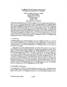
Figure 1: Camera motion compensation: Because the camera position changes over time, the point in object space which has been shaded for frame f is seen through different pixels in frames f 0 and f 00. how this recycling can be done when using the BPT algorithm to compute the native samples. Also, if the rendering process requires high order ray generation, the corresponding visibility queries must be conservatively answered. Section 4 describes a new visibility data structure that allows aggregate queries for several consecutive frames.
3.1. Native Samples and Recycled Samples We assume that the rendering algorithm used is a variant of path tracing (i.e. classical ray-tracing, Kajiya’s path-tracing, bidirectional path tracing, and so on). In such algorithms, the color of every pixel in an image is computed using several samples of the incoming radiance at several points within that pixel. Assuming for the sake of simplicity that a simple “box function” reconstruction filter is used to compute the pixel color from those samples (i.e. the color of the pixel is the average of all samples contributing to it), two types of samples are used:
3.2. The Animation Buffer A buffer must be constructed in order to store the average of contributions of native and recycled samples for each pixel. This requires the storage for each pixel of a high dynamic range sum of all contributions and a sum of their weights w. A naive approach would involve storing the corresponding entries for every pixel and every frame of the animation in RAM. This would require a huge amount of memory, and would therefore limit considerably the length of the animations which is computationally feasible. To reduce the amount of memory required by this algorithm recycling is limited to frames within the range [ f i−R , fi+R ] around the frame fi for which the native sample has been computed (refer to Figure 2). The memory requirements can be reduced even further by efficient disc caching of large portions of the animation buffer (described in Section 3.3).
• native samples, which are computed from scratch by the rendering algorithm for a given pixel and frame. • recycled samples, which are based on native samples previously computed for the same point in object space for neighboring frames. When computing a native sample for a given point Pf in the image plane of a frame f , the ray originating at the eye position and passing through Pf is traced until its intersection point Y with the nearest object is found. Then the shading computation at Y is performed and the sample value contribution to frame f is added. To derive a recycled sample for a neighboring frame f 0 based on this native sample, Y is reprojected to determine its position Pf 0 in the image plane of f 0. Note that when the camera is moving, or Y represents a dynamic object, the position of Pf 0 might be different than the corresponding position Pf (refer to Figure 1). After the reprojection step, the visibility of Y for frame f 0 must be checked before adding the recycled sample contribution to this frame.
Our algorithm works iteratively in the following way. All pixels within a given segment of S frames of the animation are iterated over. One native sample for each pixel is computed and recycled for all frames within the range [ fi−R , fi+R ] before proceeding to the next pixel. We repeat this iteration over all pixels in the S frames until the number of contributions added to them has reached a user-set threshold. We then proceed to the computation of the next segment of S frames. The total number of frames that need to be processed at once is thus S frames, plus the R frames before and after this segment, since recycled samples can contribute to them. Every time we move from one segment to the next, S frames of the animation can be finally saved to disk (refer to Figure 2).
Recycling the native sample can be seen as reevaluating the view dependent part of the rendering process to take into account the change of camera position. Typically, for a physically based rendering algorithm, it involves reevaluating the bidirectional scattering distribution function (BSDF) at point Y according to the new ray direction. Section 5 describes
The bigger the recycling radius R, the higher the number c The Eurographics Association 2003.
109
Havran et al. / An Efficient Spatio-Temporal Architecture for Animation Rendering
dering time is increased by less than 10% (e.g. with a resolution of 4000 × 4000 and S + 2R = 100, 360 MBytes of RAM would be used).
frames kept in animation buffer R
S
R current segment next segment
S frames saved on disk
Frame (time) axis
4. Multi-Frame Visibility Data Structure for Ray Tracing
Figure 2: Structure of the animation buffer: Native samples are computed for S frames and are reused to add contributions to the S + 2R frames in memory. Every time we go from one animation segment to the next, S frames are saved on disk.
An efficient data structure for visibility computations is a key part of any ray tracing based rendering algorithm. The main difference between the previous solutions designed in this context and our visibility data structure (abbreviated to MFV DS - multi-frame visibility data structure) is that MFV DS is designed to compute aggregated visibility information given a ray and all F = S + 2R frames in an animation segment (see Section 3.2).
of recycled samples that can be computed from one single native sample (supposing the corresponding point in objectspace stays visible long enough). The influence of the slice length S is more subtle. In short, increasing the length S of the slice increases the homogeneity of the distribution of native samples between all frames of the animation. To understand this, let us consider the case S = 1: in such a case a very high number of native samples would need to be computed for the first slice (or frame in this particular case) before moving to the next one. It is likely that for the next R frames the number of samples already computed (recycled from the first frame) will already be almost sufficient for every pixel. Therefore for those frames very few natives samples will be computed. In such a case, our algorithm will behave as if we were computing one reference frame every R + 1 frames, and reuse samples only for the R frames in between.
The MFV DS is constructed during a preprocessing step over a set of scene primitives (such as triangles) and subsequently used to answer visibility queries. Static primitives are represented in the MFV DS only once and animated primitives are instantiated for every frame for which their motion occurs. Each primitive instance differs only by a transformation matrix which encodes its displacement from its reference position. The MFV DS allows us to avoid redundant ray object primitive intersection computations when the ray does not hit any instantiated primitive. Also, in regions not populated by animated primitives, the same ray traversal cost as in static scenes is achieved. Our visibility data structure makes extensive use of Kd-trees which have been shown to be particularly efficient in the context of ray tracing 19, 36 . In particular, the design of MFV DS is based on the results of ray shooting algorithm for static scenes described in detail in Havran’s thesis19 .
The total number of frames kept in the animation buffer F = S + 2R is of course limited by the memory available. This organization of computation allows us to schedule and reduce the amount of work devoted to the update of our visibility acceleration data structure with respect to the movement of objects. However, increasing the number of frames kept in memory also increases the overhead of our visibility queries. Clearly, a compromise has to be made to reach maximum efficiency (see experimental results in Section 8).
Section 4.1 describes how the MFV DS is built, and Section 4.2 details how this structure is used to compute aggregated visibility queries for multiple frames. 4.1. Building the Visibility Data Structure
3.3. Disc Caching of the Animation Buffer Storing the animation buffer in the main memory can become infeasible for higher resolution of images or for a high number of frames F. To overcome memory limitations, we implemented an efficient caching scheme where the whole animation buffer is stored on the disc, and only a small part of the animation buffer is present in main memory. The animation buffer is organized in blocks of 8 × 8 pixels×8 frames (about 16 KBytes). We use a simple prime number based hashing scheme with chaining factor 2 16 . During rendering we iterate over the pixels by blocks, first visiting all pixels in the current block and then going to the next block. This scheme substantially improves coherence of accesses to the main memory and to the disc. When storing approximately 1% of the animation buffer in memory, the total renc The Eurographics Association 2003.
110
We first separate the static and animated primitives in the scene into two groups Gs and Ga, respectively. The frame interval over which the validity of the primitive is defined (the frame-tag) is attached to each primitive. Static primitives are valid for all frames while animated primitives are typically valid only for a single frame. For each animated primitive in Ga we create an instance for every frame in the current animation segment. The memory consumption overhead due to the instantiation is reasonable: Each instantiated primitive contains its frame-tag, references to its forward and inverse transformation matrices, a reference to the template primitive from which it was instantiated, and a mailbox to avoid repeated ray-primitive intersection for the same ray. Since the animation paths are typically common to many primitives simultaneously, the transformation matrices can be efficiently shared amongst
Havran et al. / An Efficient Spatio-Temporal Architecture for Animation Rendering j
Kd-trees Ka caching the result of ray-primitive intersection and ray-Kd-tree node intersections (to speed up ray traversal in Kd-tree). • a ray transformation cache storing the results of a ray transformation from scene space to the canonical space of template primitives for animated objects. This is efficient since the results for a particular ray can be shared by multiple primitives that have the same animation path. • aggregated frame information for each primitive inside j each small Kd-tree Ka . This is used to avoid traversal of those trees during FNIPsingle and Vsingle queries if no primitive valid for the required frame is inside the Kdtree.
the primitives. Informations such as material properties and geometry description are stored for the template primitives only. As a result, in our implementation, the memory taken by a single instantiated primitive is 52 bytes. In a first step, we construct a global Kd-tree Ks over all static primitives in Gs , using surface area heuristics 25 . In a second step, for all F × |Ga| instantiated primitives we then perform a hierarchical clustering 20 also using a Kd-tree with surface area heuristics 25 . We limit the number of primitives in a cluster to an order of a couple of hundred. As a result of clustering via kd-tree construction, the clusters contain primitives close in space. The use of Kd-tree in this way is justified since it provides us with clusters that fit tightly to the contained primitives, which is crucial for the efficiency of visibility queries.
In our current implementation, MFV DS can efficiently compute such aggregate visibility queries over a range F up to 250 frames. Although the number of frames of MFV DS is limited due to implementation details, it seems to be sufficient according to the results given in Section 8. Prospectively, the performance of MFV DS could be improved by using temporal bounding volumes 31 .
Assuming that clustering results in L clusters, for each j cluster we construct a separate Kd-tree Ka ( j ∈ h1, Li). In j the next step we insert all Kd-trees Ka into the leaves of the global Kd-tree Ks . Finally, we refine all the leaves of Ks changed during the insertion using the Kd-tree construction algorithm with cutting off empty space 19 . This refinement offers a good separation of all Kd-trees inserted into a leaf. Furthermore, empty spatial regions inside the leaves of Ks resulting from the insertion of smaller Kd-trees are cut off. This improves significantly the traversal cost for rays which do not hit any animated primitive.
5. Global Illumination In this section, we show as an example how estimates computed using a bidirectional path tracing (BPT) algorithm for a given frame can be recycled for use on other neighboring frames, where the camera and object positions may have changed. Using similar techniques, most global illumination rendering methods based on path-tracing should be possible to embed into our rendering architecture.
4.2. Answering the Visibility Queries The MFV DS is designed to efficiently provide an answer to the following visibility queries:
First, we review briefly the principle of BPT and introduce some notations that are used in the subsequent discussions. Then, we describe how bidirectional paths computed for a given frame f can be reused for several other frames in the simpler case of walkthrough animations. Finally, we expose the changes that have to be made to this basic reusing procedure in order to take into account the possible visibility changes in the more general case of animations of objects in the scene.
1. FNIPsingle (ray, frame) - find the nearest intersection point along a ray traced for a single frame in the current animation segment. 2. Vsingle (Point1, Point2, frame) - compute the visibility between two points for a single frame. 3. FNIPaggreg(ray, nativeFrame, visibilityMask) - find the nearest intersection point as above for a given native frame. In addition, check if the result for the native frame is valid for all other frames in the current animation segment. The visibility mask is a simple boolean array of size F used to transfer the result of this visibility computation. 4. Vaggreg(Point1, Point2, visibilityMask) - compute the visibility between two points at once for all frames in the current animation segment. The result is stored again in the visibility mask.
5.1. Bidirectional Path Tracing Let us review briefly how the radiance along rays arriving at the eye can be estimated by the BPT algorithm. The basic idea is that for each estimate, a path is stochastically generated from both the eye point and a light source. Then, all N hit points from the light path are connected to the M hit points on the eye path by casting shadow rays. Thus, an estimate is obtained by gathering light through all the N × M resulting paths (if the shadow rays are not occluded, refer to Figure 3), resulting potentially in N × M contributions. These contributions, combined using an appropriate heuristic 23, 34 , give an unbiased estimate < L f > of the radiance
The efficiency of MFV DS is improved by using the following techniques: • a primitive shadow cache that stores the last occluding static primitive to speed up the Vsingle and Vaggreg queries. • mailboxes for instantiated primitives and small inserted
c The Eurographics Association 2003.
111
Havran et al. / An Efficient Spatio-Temporal Architecture for Animation Rendering
s?f is the BSDF value at point Y where the incoming direction is the second point on the eye path and the outgoing direction is the position of the eye for frame f .
along the ray arriving at the eye point. Formally this estimate can be decomposed in the sum of two quantities: < L f >=
N
∑ Cf
i,1
i=0
N
M
+∑
∑ Cf
i, j
In case the BSDF values at Y are very low for the native frame f (this may happen, for example when the corresponding surface is a mirror, or glass), the ratios in Equation (1) can tend to infinity. Similarly, when the BSDF ratio is very small, then the corresponding path (generated using importance sampling) is very unlikely for the current viewpoint. It is therefore better not to reuse estimates when a BSDF ratio becomes much smaller or much higher than 1.
i=0 j=2
where the first sum is the total of all contributions given by the connection of the first hit point Y of the eye path to all points on the light path and the second is the sum of all the other contributions (note that for all these contributions, the incoming light direction at Y is the one of the second hit point of the eye path).
light source
new viewpoint
In practice, this means that we rely only on native estimates to render directly visible mirror-like surfaces when the camera is moving. In order to be able to reuse the the native estimate in such cases, one should track the reflected point in image space instead of the directly visible point, which is a considerably more complicated task30 . On the other hand, all estimates involving mirror-like surfaces only for secondary and higher-order rays can be directly reused in our approach.
light path
C 11
C 03
screen
C 12
C 02 C 01
C 13 C 23
shadow rays
C 22 eye path
C 21
original viewpoint
Y
As a consequence the efficiency of our reusing scheme decreases when the total area in screen space covered by highly specular surfaces increases. In the worst case scenario, where every directly visible surface is a mirror, no sample would be reused. Therefore the rendering time would be equivalent to a simple frame by frame computation.
screen
Figure 3: Example of connections between all points on the eye and light paths for N = 2 and M = 3. The BSDFs corresponding to the dashed connection rays need to be recomputed to take into account the viewpoint movement.
5.3. Visibility Changes in Animated Scenes 5.2. Taking the Camera Motion into Account
When some objects are moving in the scene, in order to be conservative our recycled estimates must take into account the potential visibility changes between two points on the eye path or the light path or for the shadow rays connecting the light path and the eye path. This is solved using the visibility acceleration data structure described in Section 4.
If a native estimate, composed of up to N × M contributions has been computed for frame f , a recycled estimate (for a potentially different pixel) can be computed in a much shorter time for a neighboring frame f 0. For rendering a “walkthrough” animation (i.e. only the camera is moving, the objects in the scene stand still), we need to:
When shooting the eye and light paths for the native estimate, the FNIPaggreg visibility query is used to determine the hit points composing the path and simultaneously check if the corresponding rays are also valid for the other frames within the “recycling radius” R (see Section 3). Whenever the hit points on the eye path or the light path are located on a moving object, we do not reuse the corresponding contributions. However, in such cases, in order to avoid biasing the solution, for the frames for which these contributions have been invalidated, it is necessary to re-compute a new path starting from the point where it hit a moving object.
• find where the point Y we are tracking in object space reprojects in image space and check if it is still visible (refer to Section 3). • recompute the bidirectional scattering distribution function (BSDF) at Y for the new eye direction (since the camera moved) and modify the various contributions accordingly. Our recycled estimate < L0f > is therefore computed in the following way : N
N
< L0f >= ∑ C f 0 + ∑ i=0
i,1
M
∑ Cf
i=0 j=2
where:
i, j 0
N
sif 0
i=0
sif
=∑
i,1
Cf +
s?f 0 s?f
N
M
∑ ∑ Cf
i=0 j=2
i, j
(1)
sif is the BSDF value at point Y where the incoming direction is the ith point on the light path and the outgoing direction is the position of the eye for frame f .
Also, for each connection between the eye and light paths, the visibility is checked using the Vaggreg query simultaneously for all frames in the recycling radius. In this case, connections that become occluded by a moving object can be safely discarded for the corresponding frames. Therefore, for each eye or light path segment and each connection, we get a visibility boolean mask encoding for which frame it is valid and for which it is occluded. By using
c The Eurographics Association 2003.
112
Havran et al. / An Efficient Spatio-Temporal Architecture for Animation Rendering
tracking was also used to reduce flickering in interactive ray tracing 27 .
simple bitwise boolean operations on those masks it is then easy to determine for which frame in [ f i−R , fi+R ] a given contribution C i, j corresponding to a connection (i, j) is valid.
Our goal is to estimate the energy contribution of p within time interval T f to all pixels located on the trajectory drawn by point PY which is the projection of Y on the image plane f1 . For simplicity we assume that the trajectory can be well approximated by the line segment P1 P2 connecting P1 and P2 , and PY is moving along this trajectory with a constant velocity v = kP1 P2 k/Tf . In such a case all pixels i overlapped by P1 P2 can be identified using a DDA algorithm 8 . Also, the corresponding sub-segment lengths v∆τi within the pixels, which are required to weight the energy transfered along p to those pixels, are obtained during the DDA computation 7 . Here ∆τ = τout − τin , where τin and τout are the time ini i i i i stances measured from f 1 when PY enters to and exits from pixel i, respectively.
6. Shading Computation Visually attractive appearance of surfaces in the production quality animation is achieved through applying complex shader functions 2 for each rendered point. Often the cost of shading computation which may include 2D and 3D procedural texturing, bump and displacement mapping, sophisticated models of light interactions with surfaces dominates the overall rendering cost. It is not unusual to connect various shader components into nested cascades of dependency. Also, procedural textures usually require careful antialiasing which often is more costly than texture pattern computation itself 2 . In our animation framework, significant parts of the shader cost can be eliminated by reusing information for a given sample point between frames. Also, by reusing the same sample point, aliasing can be reduced.
pixels
P1
Shading functions are split into view-independent and view-dependent components, where the former is computed only once for a given sample point and the latter is recomputed for each frame. It is worth noting that in our BPT technique we need to recompute the view-dependent component only for sample points that are hit by primary rays, while for the remaining path segments shading results are just reused. Moreover, for such segments, we can avoid the redundant computation of importance sampling for shader defined BSDFs, which can be costly for sophisticated reflectance functions in frame-by-frame rendering.
P2
∆τ PY
TS /2
Figure 4: Motion blur processing: The radiance incoming from sample point Y is distributed to all pixels along segment P1 P2 traversed by PY within the shutter opening time TS /2 (marked in the bold line). The radiance contributes to each pixel in a proportion to its traversal time ∆τ. The amount of motion blur is controlled by modifying the time TS during which the shutter is opened. Therefore, the energy of p is distributed only to those pixels i which are traversed by PY within the time intervals of TS /2 seconds after f1 and symmetrically TS /2 seconds before f 2 (refer to Figure 4). By repeating the same processing for all subsequent frame pairs the full shutter speed TS is considered for each frame 7 .
7. Motion Blur A common way to combat spatio-temporal aliasing is to introduce motion blur, which reduces the perceivability of image artifacts resulting from an inadequate sampling and reconstruction of high spatio-temporal frequencies in the image. Motion blur is also a desirable effect when simulating animations captured using optical systems with controllable shutter speed.
Whenever Y is occluded for f 2 but visible for f 1 (resp. occluded for f 1 but visible for f 2), the energy is only distributed for the TS /2 seconds after f 1 (resp. the TS/2 seconds before f2). However, we do not take into account possible visibility changes within those TS/2 seconds. This approach is motivated by similar simplifications used in the motion blur solution of the Maya Rendering system without causing perceivable degradation of animation quality 32 . Also, possible visibility artifacts are created along the direction of objects or camera motion which is less objectionable.
Our motion blur algorithm operates on single sample values provided by path tracing and fits well into our scheme of reusing those samples for neighboring frames in an animation sequence. The algorithm uses sample values in two subsequent frames which can be the actual animation frames or virtual frames inserted between a pair of the actual frames to improve the temporal sampling rate.
The radiance contributed from path p to a pixel i should be computed by integrating the radiance L(PY ) over the time interval ∆τi and normalizing by TS . In practice, L(PY ) is derived through the linear interpolation between L(P1) and L(P2) values.
Let us consider two subsequent frames f 1 and f2 separated by a time interval T f , and a light path p which intersects the image planes of f 1 and f2 at points P1 and P2, respectively. The primary (eye) ray of p in both cases hits the same point Y , which is achieved by the reprojection of Y from f1 to f2 (refer to Figure 1). A similar intersection point
Our motion blur approach is similar to the technique developed by Brostow and Essa 7 for the post-processing of animation frames using optical flow estimates. However, our animation rendering framework derives more precise trajecc The Eurographics Association 2003.
113
Havran et al. / An Efficient Spatio-Temporal Architecture for Animation Rendering
fined spatial locations and time instances. To reduce excessive blurring the temporal domain is supersampled up to six times. In our framework, the number of explicit samples in the temporal domain can be reduced because our samples are motion-compensated.
tories of PY motion within the image plane. Also, visibility changes and reflected lighting information are better resolved. 7.1. Discussion In this section we compare the advanced motion blur solutions used in the Maya Rendering system 32 and PhotorealisticRenderMan (PRMan) 11, 2 with our technique described in the previous section.
8. Results In order to estimate the efficiency of the different features of our new rendering architecture, we computed animations and walkthroughs for several scenes using bidirectional path tracing and simple ray tracing, with and without motion blur. In all tested cases we obtained significant speedup and a better quality, due to the reduction of flickering when compared to frame-by-frame results. In particular, an interesting byproduct of our sample recycling scheme is that it makes the stochastic noise of bidirectional path tracing coherent in object space. Thus, it avoids the shimmering artifacts that would result from a frame-by-frame computation.
In the Maya Rendering system the visibility and shading components of motion blur are considered separately as a function of time. In the visibility computation the time interval ∆τlj is computed in which a given object l is visible for a j
given sample point Pl in the image plane 32 . Such computations are performed for all objects in the scene and all pixels. j The number of Pl is adaptively adjusted for each pixel based on the variance in the lengths of ∆τlj for this pixel and its neighbors. Then the shading computation is performed and for each ∆τlj stratified stochastically samples in time are selected. For each one a temporal sample shading is computed for the corresponding location along the so-called objecttime visible curves on the object l. The algorithm leads to excellent results but the visibility and shading computations are costly.
All timings in this section are given for frames of resolution 320 × 240 and are measured on a Pentium 4, 2.6 GHz processor. They can be easily extrapolated for higher resolutions since the complexity of path tracing techniques is linear with respect to the number of pixels. For these tests we used disc caching described in Section 3.3. The size of animation buffer part that is stored in memory (refer to Section 3.3) was less than 100 MB and the cache hit ratio of access to the animation buffer stored in a file was better than 99.92%.
In our framework the motion blur computation is more precise because we operate on the level of single samples and we average the results for many of such samples for each pixel. Our spatio-temporal samples incorporate both the geometrical and shading information. Also, our approach is more efficient and easier to implement because of the following reasons:
We used bidirectional path tracing to render a walkthrough in the C LOISTER scene composed of 80, 000 triangles with 150 samples per pixel (refer to Figure 5). We used an animation segment length S = 50 frames and a recycling radius R = 100 frames. The average rendering time per frame was 120 seconds, which is 8.6 times faster than using a frame-by-frame approach. Adding motion blur increased the rendering time to 150 seconds.
• The computation of the time interval ∆τ is performed in the image space using a fast DDA-like algorithm instead of the object space computation as required in the Maya system. • The shading computation is always performed for the same sample point through reprojection. This is much faster than searching for such a point along object-time visible curves 32 . • Shading samples reuse information computed from previous frames. Only the visibility and BSDF re-weighting for changing viewing directions must be performed. Sung et al. do not report on any use of temporal coherence in the shading computation, which seems to be difficult in their approach. • Shading is affected only by changes in lighting and viewing direction and is not affected by textures as in the Maya system. This means that shading information can be sampled more sparsely in the temporal domain.
We also performed tests for the L OBBY scene (see Figure 5) composed of 17, 000 triangles and illuminated by 51 light sources. In order to be able to reduce the variance due to the high number of light sources in this scene, we designed a scheme to stochastically select emitting light sources according to their contribution to the total irradiance at the point currently considered. For this scene, we considered the following cases: moving camera and objects (MCMO), moving camera only (MC), and moving objects only (MO). For each we measured: • the average computation time per frame of the animation, • the speedup obtained when compared to frame-by-frame computations, • the percentage of native samples when compared to the total number of samples (native and recycled) necessary to compute the animation,
In PRMan, sample locations in the spatio-temporal domain are selected stochastically and their values are linearly interpolated based on precomputed shading values at prede-
Table 1 summarizes the obtained results (without motion
c The Eurographics Association 2003.
114
Havran et al. / An Efficient Spatio-Temporal Architecture for Animation Rendering
(a)
(b)
(c)
Figure 5: Example frames from our animations. From left to right, (a) an overview of the C LOISTER scene, (b) a motion-blurred frame from the C LOISTER animation, and (c) an overview of the L OBBY scene. Table 1: Timing statistics for the L OBBY scene animations. MCMO
MC
MO
Computation time (per frame) [sec]
415
363
240
Speedup
7.7×
8.8×
13.3×
4.7
3.4
2.4
Proportion of native samples [%]
be computed once and for all using our aggregated queries (since the camera is static) and BSDF values do not need to be recomputed. Possible improvements to reduce this recycling cost in the general case are discussed in Section 9.
Table 2: Memory statistics for MFV DS for the L OBBY scene animations. INST. OBJS .
CLUSTERS
SIZE
1
1,080
15
0.75 MB
10
10,800
239
4.01 MB
50
54,000
1,530
28.68 MB
100
108,000
3,231
68.92 MB
150
162,000
9,218
171.40 MB
250
270,000
19,494
399.40 MB
FRAMES
We also computed the L OBBY animation using simple ray tracing and procedural shaders (see Section 6), to evaluate the speedup that can be obtained without global illumination using our rendering framework. For a 320 × 240 animation, with 16 times supersampling, we achieve a speedup of 2.6 when compared to frame by frame rendering. See Figure 7 for sample frames of our animations described above†. In order to determine the influence of the size of the animation buffer F = S + 2R on the performance of our algorithm, we computed several smaller scale animations in the L OBBY scene for moving camera with animated and static objects (160 × 120, 200 frames, 40 samples per pixel) with varying F (we set R = 2S, so e.g. for F = 250, we have R = 100 and S = 50). The results are shown in Figure 6. It appears that in both cases, a good choice of F would be within 60 to 90 frames. Note that this result is probably dependent on the scene and on the animation. Too large an animation buffer seems to impair the performances of the algorithm. This can be due to increased costs of our aggregated visibility queries, as well as reduced coherence in memory accesses resulting from a too large recycling radius R.
blur), which lead us to several comments. First, our new architecture achieves significant speedup: our approach performs about 7 to 13 times faster than traditional frame-byframe computations. At the same time the quality of animation is much higher because temporal flickering due to the stochastic noise incoherence is substantially suppressed. Even for a small number of BPT samples per pixel the noise might be visible but remains static, looking like a texture pattern rigidly attached to rendered objects. Second, the very low number of native samples shows that our architecture manages to reuse a fair amount of samples. Therefore, further reduction of the computation time may be achieved by decreasing the cost of recycling. It should be noticed that, in the case of static camera and moving objects, we obtain a better acceleration factor partly because of some optimizations of the recycling function for this special case: samples always reproject to the same pixel, direct visibility can
We measured the memory taken by MFV DS with respect to the number of frames in Table 2, for the L OBBY scene.
† Project related WWW page is at http://www.mpi-sb.mpg.de/resources/anim/EGSR03/. c The Eurographics Association 2003.
115
Havran et al. / An Efficient Spatio-Temporal Architecture for Animation Rendering 4400
way. As a result, the memory requirements of our algorithm are reasonable.
"MCMO" "MC"
4200
We foresee several ways of improving our algorithm’s performance. Bekaert et al. 4 proposed to reuse light paths for multiple neighboring pixels which leads to significant speedup of the path tracing algorithm for static images. Applying a similar technique in our bidirectional path tracing should result in similar speedup. Also, it would be interesting to extend their mathematical framework to the temporal domain in order to cover both approaches in an unified way. Further speedup of ray tracing and bidirectional path tracing can also be expected by improving the efficiency of direct visibility tests for reprojected samples. For example, Bala et al. 3 report consequent performance increase when using a shaft culling approach. Sung et al. 32 propose simple heuristics, which are successfully used in the Maya Rendering System, to skip the visibility test for many samples based on the results obtained for neighboring samples. Another natural extension would be the parallelization of our rendering architecture.
Time (sec.)
4000
3800
3600
3400
3200
3000
2800
0
50
100
150
200
250
Animation Buffer Size F (in frames)
Figure 6: Change in computation time as a function of the animation buffer size F. For an animation buffer size F within the range 50 to 100 (which has been shown best by our previous experiment), the memory cost of MFV DS is manageable for current desktop computers.
Acknowledgements
While we did not experiment with deformable objects we believe that our framework can handle them efficiently as well. All traced light paths interfering with such objects must simply be recomputed in the same way as animated rigid objects. Building the MFV DS would require handling a different number of scene primitives (triangles) whose scales may change from frame to frame. Our shading and motion blur approaches would require surface parameterization to ensure that the corresponding points on the deformable surface can always be found for all considered frames.
We would like to thank Polina Kondratieva and Markus Weber for help in preparing scenes used in our animation examples. This work was supported partly by the European Community within the scope of the RealReflect project IST2001-34744 “Realtime visualization of complex reflectance behavior in virtual prototyping”. References 1.
9. Conclusions
2.
We have presented a new architecture for animation rendering that can be applied to several types of ray-based rendering methods. In particular, we demonstrated its use to reduce the computational cost and flickering of animations rendered by bidirectional path tracing and ray tracing using complex surface shaders. We also showed that it allows to perform motion blur on the computed images at a reasonable added cost.
3.
4.
Instead of performing frame-by-frame and pixel by pixel sampling of the incoming radiant flux, our approach uses motion compensation techniques to track samples in image space and reuse them over multiple frames, thus reducing the computation time and flickering due to aliasing or stochastic noise. Although, we have to deal with processing several frames in an animation buffer, through the use of a caching strategy, we can transfer large portions of this buffer to disk. This strategy relies on the fact that, since we know the pixel trajectories in image space, it is possible to greatly enhance the coherence of writing accesses in the animation buffer by concentrating on groups of pixels that move in a coherent
5.
6.
7.
c The Eurographics Association 2003.
116
S.J. Adelson and L.F. Hughes. Generating Exact RayTraced Animation Frames by Reprojection. IEEE Computer Graphics & Applications, 15(3):43–53, 1995. 2 A.A. Apodaca and L. Gritz. Advanced RenderMan. Morgan Kaufmann, 1999. 2, 3, 8, 9 K. Bala, J. Dorsey, and S. Teller. Ray-Traced Interactive Scene Editing Using Ray Segment Trees. In Proceedings of the 10th Eurographics Workshop on Rendering, 1999. 2, 11 P. Bekaert, M. Sbert, and J. Halton. Accelerating Path Tracing by Re-Using Paths. In Proceedings of the 13th Eurographics Workshop on Rendering, pages 125–134, 2002. 11 G. Besuievsky and X. Pueyo. Animating Radiosity Environments Through the Multi-Frame Lighting Method. Journal of Visualization and Computer Animation, 12(2):93–106, 2001. 3 N. Briére and P. Poulin. Hierarchical View-Dependent Structures for Interactive Scene Manipulation. In Proceedings of SIGGRAPH 96, Computer Graphics Proceedings, Annual Conference Series, pages 83–90, 1996. 2 G.J. Brostow and I. Essa. Image-Based Motion Blur for Stop Motion Animation. In Proceedings of ACM SIG-
Havran et al. / An Efficient Spatio-Temporal Architecture for Animation Rendering
8.
9.
10.
11.
12.
13.
14.
15.
16. 17.
18.
19.
20. 21. 22.
23.
ven, 1996. 3, 6 24. J. Lext and T. Moller. Towards Rapid Reconstruction for Animated Ray Tracing. In Short Presentations, pages 311–318. Eurographics, 2001. 3 25. J.D. MacDonald and K.S. Booth. Heuristics for ray tracing using space subdivision. In Proceedings of Graphics Interface ’89, pages 152–63. Canadian Information Processing Society, 1989. 6 26. E. Maisel and G. Hegron. A Realistic Image Synthesis of Animation Sequences Based on Temporal Coherence. In 3rd Eurographics Workshop on Animation and Simulation. Elsevier Science Publishers B.V., 1992. 2 27. W. Martin, E. Reinhard, P. Shirley, S. Parker, and W. Thompson. Temporally coherent interactive ray tracing. Journal of Graphics Tools, (2):41–48, 2002. 8 28. K. Myszkowski, T. Tawara, H. Akamine, and H.-P. Seidel. Perception-Guided Global Illumination Solution for Animation Rendering. In Proceedings of ACM SIGGRAPH 2001, Computer Graphics Proceedings, Annual Conference Series, pages 221–230, 2001. 3 29. M. Shinya. Spatial Anti-aliasing for Animation Sequences with Spatio-temporal Filtering. In Proceedings of SIGGRAPH 93, Computer Graphics Proceedings, Annual Conference Series, pages 289–296, 1993. 2, 3 30. M. Shinya. Improvements on the Pixel-tracing Filter: Reflection/Refraction, Shadows, and Jittering. In Graphics Interface ’95, pages 92–102, 1995. 2, 7 31. O. Sudarsky and C. Gotsman. Output-sensitive visibility algorithms for dynamic scenes with applications to virtual reality. Computer Graphics Forum, 15(3):249– 258, 1996. 6 32. K. Sung, A. Pearce, and C. Wang. Spatial-Temporal Antialiasing. IEEE Transactions on Visualization and Computer Graphics, 8(2):144–153, 2002. 2, 3, 8, 9, 11 33. P. Tole, F. Pellacini, B. Walter, and D.P. Greenberg. Interactive Global Illumination in Dynamic Scenes. ACM Transactions on Graphics, 21(3):537–546, 2002. 3 34. E. Veach. Robust Monte Carlo Methods for Light Transport Simulation. PhD thesis, Stanford University, 1997. 6 35. I. Wald, T. Kollig, C. Benthin, A. Keller, and P. Slusallek. Interactive Global Illumination. In Proceedings of the 13th Eurographics Workshop on Rendering, pages 15–24, 2002. 3 36. I. Wald, P. Slusallek, C. Benthin, and M. Wagner. Interactive Rendering with Coherent Ray Tracing. Computer Graphics Forum, 20(3):153–164, 2001. 5 37. B. Walter, G. Drettakis, and S. Parker. Interactive Rendering using the Render Cache. In Proceedings of the 10th Eurographics Workshop on Rendering, pages 235–246, 1999. 3
GRAPH 2001, Computer Graphics Proceedings, Annual Conference Series, pages 561–566, 2001. 8 B. Cabral and L.C. Leedom. Imaging vector fields using line integral convolution. In Proceedings of ACM SIGGRAPH 93, Computer Graphics Proceedings, Annual Conference Series, pages 263–272, 1993. 8 M. Cammarano and H.W. Jensen. Time Dependent Photon Mapping. In Proceedings of the 13th Eurographics Workshop on Rendering, pages 135–144, 2002. 3 J. Chapman, T.W. Calvert, and J. Dill. Spatio-Temporal Coherence in Ray Tracing. In Graphics Interface ’91, pages 101–108. Canadian Information Processing Society, 1991. 2 R.L. Cook, L. Carpenter, and E. Catmull. The Reyes Image Rendering Architecture. In Computer Graphics (Proceedings of ACM SIGGRAPH 87), 21, pages 95– 102, 1987. 3, 9 R.L. Cook, T. Porter, and L. Carpenter. Distributed Ray Tracing. In Computer Graphics (Proceedings of ACM SIGGRAPH 84), 18, pages 137–145, 1984. 3 C. Damez, K. Dmitriev, and K. Myszkowski. State of the art in global illumination for interactive applications and high-quality animations. Computer Graphics Forum, 22(1):55–77, 2003. 3 K. Dmitriev, S. Brabec, K. Myszkowski, and H.-P. Seidel. Interactive Global Illumination Using Selective Photon Tracing. In Proceedings of the 13th Eurographics Workshop on Rendering, pages 25–36, 2002. 3 J. Döllner and K. Hinrichs. A Generic Rendering System. IEEE Transactions on Visualization and Computer Graphics, 8(2):99–118, 2002. 2 D.E. Knuth The Art of Computer Programming, volume 3. Addison-Wesley, 1973. 5 A.S. Glassner. Spacetime Ray Tracing for Animation. IEEE Computer Graphics & Applications, 8(2):60–70, 1988. 3 E. Gröller and W. Purgathofer. Using Temporal and Spatial Coherence for Accelerating the Calculation of Animation Sequences. In Eurographics ’91, pages 103–113, 1991. 3 V. Havran. Heuristic Ray Shooting Algorithms. PhD thesis, Czech Technical University in Prague, 2000. 5, 6 A.K. Jain and R.C. Dubes. Algorithms for Clustering Data. Prentice Hall, 1988. 6 H.W. Jensen. Realistic Image Synthesis Using Photon Mapping. AK, Peters, 2001. 3 D.A. Jevans. Object Space Temporal Coherence for Ray Tracing. In Graphics Interface ’92, pages 176– 183, 1992. 2 E. Lafortune. Mathematical Models and Monte Carlo Algorithms. PhD thesis, Katholieke Universiteit Leu-
c The Eurographics Association 2003.
117
Havran et al. / An Efficient Spatio-Temporal Architecture for Animation Rendering
(a)
(b)
(c)
Figure 7: Example frames from our animations: (a) the C LOISTER scene rendered using bidirectional path tracing with motion blur, (b) the L OBBY scene rendered using ray tracing with procedural shaders, and (c) the L OBBY scene rendered by bidirectional path tracing.
c The Eurographics Association 2003.
303