IEEE JOURNAL OF SOLID-STATE CIRCUITS, VOL. 36, NO. 11, NOVEMBER 2001
1599
An Embedded 32-b Microprocessor Core for Low-Power and High-Performance Applications Lawrence T. Clark, Member, IEEE, Eric J. Hoffman, Jay Miller, Manish Biyani, Yuyun Liao, Associate Member, IEEE, Stephen Strazdus, Michael Morrow, Kimberley E. Velarde, and Mark A. Yarch
TABLE I DEVICE PARAMETERS
Abstract—An embedded RISC microprocessor core fabricated in a six-layer metal 0.18- m CMOS process implementing the ARM™ V.5TE instruction set is described. The core described is the first implementation of the Intel XScale Microarchitecture™. (ARM is a registered trademark of Advanced RISC Machines, Ltd.) The microprocessor core, which includes caches, memory management units, and a bus controller, comprises a hard-embedded block 16.77 mm2 in size. The implementation is primarily custom logic in a variety of circuit styles. The processor dissipates 450 mW at 1.3 V, 600 MHz, and scales between 55 mW at 0.7 V, 200 MHz, and 900 mW at 1.65 V, 800 MHz. Architectural performance is 1000 MIPS at 800 MHz with efficiency ranging from over 850 MIPS/W at 1.65 V to over 4500 MIPS/W at 0.75 V. Architectural and circuit design approaches for low power and high performance are described and measured results from the initial implementation are shown. The first implementation VLSI chip has a 3.3-V pin interface and supports a 0.75–1.65-V core voltage range. Index Terms—Cache memories, CMOS integrated circuits, microprocessors.
I. INTRODUCTION
E
MBEDDED microprocessor applications encompass a wide range from high performance in system-on-a-chip (SOC) devices that supply networking, I/O processing, and modem banks, to power-consumption-limited personal digital assistants and cell phones. While the latter require increasing performance for increased functionality such as handwriting and voice recognition, low active and standby power consumption is the primary consideration for adequate battery life. The former applications, which are “tethered” or nonbattery powered, still desire low power but demand the highest possible performance. In these applications, low power enables greater integration and lower package cost due to improved thermal characteristics. The first embodiment of the Intel® XScale Microarchitecture™ described here was developed to enable application specific standard product (ASSP) SOC devices which provide up to 1000 MIPS of processing power in tethered applications while allowing up to 4500 MIPS/W under battery power. The microprocessor delivers the highest currently available performance under 0.5 W, when measured running Dhrystone 2.1. High absolute performance at the process maximum voltage enables compelling performance at low voltage levels and provides high Manuscript received March 17, 2001; revised June 18, 2001. The authors are with Intel Corporation, Chandler, AZ 85226 USA (e-mail:
[email protected]). Publisher Item Identifier S 0018-9200(01)08214-2.
MIPS/W due to the well-known quadratic dependence of power on operating voltage. In this manner, the same design can meet what appear initially to be conflicting goals of low power and high performance. Circuit and process techniques allow low average power as well as standby current of 100 A at 1 V and room temperature. In this paper, performance of the implementation is reviewed and details of the architectural and circuit approaches are presented. Section II briefly describes the process technology utilized. Section III describes the processor microarchitecture, while the circuit implementation details, focusing on clocking and caches, comprises Section IV. The physical implementation is shown in Section V, and the simulated and measured performance is discussed in Section VI. In this section, the power-down modes and use of dynamic power supply voltage scaling is also described. II. PROCESS TECHNOLOGY The core is implemented in an n-well on P-epi 0.18- m lithography process similar to that described in [1]. This process implements a 5% optical shrink from that process, as well as numerous changes to both the transistors and interconnect to support SOC applications. Process characteristics are shown in Table I. The additional 8-nm gate oxide provides 5-V tolerance to allow interfacing to standard memory and I/O such as SDRAM and PCI. The SRAM cell is 5.05 m in size. The six layers of interconnect are aluminum with SiOF dielectric ) to limit capacitance. Metals 2 through material ( 5 support the same pitch to provide high routing density on standard-cell-based autoplace and route-designed blocks, as shown in Fig. 1.
0018–9200/01$10.00 ©2001 IEEE
1600
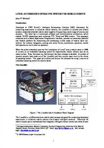
Fig. 1.
IEEE JOURNAL OF SOLID-STATE CIRCUITS, VOL. 36, NO. 11, NOVEMBER 2001
Process SEM cross section.
The process was raised from [1] to limit standby power. Circuit design and architectural pipelining ensure low voltage performance and functionality. To further limit standby current in handheld ASSPs, a longer poly target takes advantage of the versus dependence and source-to-body bias is used in standby mode. All core to electrically limit transistor nMOS and pMOS transistors utilize separate source and bulk connections to support this. The process includes cobalt disilicide gates and diffusions. Low source and drain capacitance, as well as 3-nm gate-oxide thickness, allow high performance and low-voltage operation. III. ARCHITECTURE The microprocessor contains 32-kB instruction and data caches as well as an eight-entry coalescing writeback buffer. The instruction and data cache fill buffers have two and four entries, respectively. The data cache supports hit-under-miss operation and lines may be locked to allow SRAM-like operation. Thirty-two-entry fully associative translation lookaside buffers (TLBs) that support multiple page sizes are provided for both caches. TLB entries may also be locked. A 128-entry branch target buffer improves branch performance a pipeline deeper than earlier high-performance ARM designs [2], [3]. A. Pipeline Organization To obtain high performance, the microprocessor core utilizes a simple scalar pipeline and a high-frequency clock. In addition to avoiding the potential power waste of a superscalar approach, functional design and validation complexity is decreased at the expense of circuit design effort. To avoid circuit design issues, the pipeline partitioning balances the workload and ensures that no one pipeline stage is tight. The main integer pipeline is seven stages, memory operations follow an eight-stage pipeline, and when operating in thumb mode an extra pipe stage is inserted after the last fetch stage to convert thumb instructions into ARM instructions. Since thumb mode instructions [11] are 16 b, two instructions are fetched in parallel while executing thumb instructions. A simplified diagram of the processor pipeline is
Fig. 2. Microprocessor pipeline organization.
shown in Fig. 2, where the state boundaries are indicated by gray. Features that allow the microarchitecture to achieve high speed are as follows. The shifter and ALU reside in separate stages. The ARM instruction set allows a shift followed by an ALU operation in a single instruction. Previous implementations limited frequency by having the shift and ALU in a single stage. Splitting this operation reduces the critical ALU bypass path by approximately 1/3. The extra pipeline hazard introduced when an instruction is immediately followed by one requiring that the result be shifted is infrequent. Decoupled Instruction Fetch. A two-instruction deep queue is implemented between the second fetch and instruction decode pipe stages. This allows stalls generated later in the pipe to be deferred by one or more cycles in the earlier pipe stages, thereby allowing instruction fetches to proceed when the pipe is stalled, and also relieves stall speed paths in the instruction fetch and branch prediction units. Deferred register dependency stalls. While register dependencies are checked in the RF stage, stalls due to these hazards are deferred until the X1 stage. All the necessary operands are then captured from result-forwarding busses as the results are returned to the register file. One of the major goals of the design was to minimize the energy consumed to complete a given task. Conventional wisdom has been that shorter pipelines are more efficient due to re-
CLARK et al.: EMBEDDED 32-b MICROPROCESSOR CORE
1601
duced number of clocked elements and speculative operations in the core. However, lengthening the pipeline allows power reduction at a given frequency through a combination of the greater frequency that can be achieved at the same voltage (or lower voltage at the same frequency) and limiting the need for high-speed, i.e., high-power, circuit design techniques. As frequency is increased the effect of memory latency on overall performance is also increased. The microarchitecture decouples execution from external memory to avoid this, by including the ability to buffer up to eight external memory read requests, a nonblocking data cache, an eight-entry write buffer that supports coalescing of multiple requests, writeback caching, configurable data cache allocation policies, and cache locking. B. Cache Architecture The cache design utilizes high set associativity content-addressable memory (CAM)-based virtually addressed tags [3], [4] that eliminate the x address decoder and provides low power in a single cycle cache. While potentially shortening the pipeline by allowing concurrent TLB and cache lookup, virtual addressing invites unique challenges in the data cache, as entries which are replaced by writes must be “unreplaced” upon a TLB miss or permission violation, which is known only after the fact. The pipelined 32-kB instruction and 32-kB data caches are divided into banks, which are 32-way set associative. The high associativity is more important to power than to architectural performance, where 32 ways is past the point of diminishing returns [5]. Comparison to similar speed designs showed that the power savings achieved versus a conventional 4-way set associative design is approximately 4 . All cache operations, load, store, fill, and replace can issue on each cycle. A read or write yields one 32-b word or one to four written bytes, respectively. Fill and flush operations are 64 bits wide. Line fill operations begin with a tag write operation, which can occur concurrently with an eviction from the data array. The tag valid bit is then set. Fills are completed when the data is made available from the bus unit by writing two words (as well as one fourth of the physical address) in four subsequent cycles. Subsequently, including the tag valid bit in the match operation validates fills. The data valid bit is not set until the line data is complete, which allows hit-under-miss operation. A round-robin replacement scheme is used due to the impracticality of implementing a least recently used replacement scheme. Line-based locking allows predictable response time for critical accesses, e.g., commonly used data or interrupt handler code. This is implemented with a move-to-coprocessor (MCR) instruction to lock the line upon loading it [6]. A data “minicache” which is 2 kB in size and has an independent round-robin replacement mechanism is provided. This allows large data sets with high spatial locality, e.g., graphics buffers, to be cached without evicting data with more temporal locality from the main data cache. C. Multiply–Accumulator The multiply–accumulator (MAC) supports single cycle throughput for 16-b 32-b operations and 16-b SIMD opera-
Fig. 3. Multiplier–accumulator architecture.
tions for audio processing. In the latter case, a 32-b register is treated as two 16-b values. The MAC leverages the advantage of a 16-b encoding scheme without adding extra delay to the faster four-stage Wallace tree of a 12-b encoding scheme. Whereas a conventional 16-b encoding requires five stages of 3-to-2 carry–save adders (CSA), and a 12-b encoding scheme, four stages of CSA, the lack of feedback on the Wallace tree in the first cycle allows improvement. The MAC encodes 16-b of the multiplier in the first cycle (the upper MUX inputs in Fig. 3) and encodes 12-b of the multiplier for the rest of the cycles with four stages (the lower MUX inputs in the figure). Eight partial products are generated in the first cycle and six partial products along with the intermediate feedback carry and sum vectors in the other cycles to fill eight slots. A[31:0] is a 32-b multiplicand, B[31:0] is a 32-b multiplier, and C[31:0] is a 32-b accumulate data. Two 40-b accumulators increase the multiply instruction throughput by avoiding data dependencies without requiring high circuit speed, thus limiting power. Forty-bit accumulators increase performance and precision of audio coding algorithms by allowing infrequent overflow checking. The accumulators are implemented as a conventional carry–lookahead design. The accumulator results are combined upon the writeback to the register file by the adder shown at the lower right in Fig. 3. To support 16-b single-instruction multiple data (SIMD) operations, multiply and load double word (LDRD) instructions are added, the former to the coprocessor instruction space. Both require two cycles to complete, and when issued in alternating cycles, utilize the full issue bandwidth of the microprocessor to allow up to 0.85 MACs/MHz on some DSP algorithms. These 16-b DSP extensions include a SIMD instruction and multiply with implicit accumulate (MIA) instructions. The basic SIMD operation, MIAPH [6], treats two 32-b registers as two pairs of 16-b values. The upper 16 bits of each register are multiplied together and the lower 16 bits are also multiplied together. The results are then added to the contents of the 40-b accumulator. The MIAxy MAC instruction multiplies two 16-b values, taken from either the upper or low two bytes of the two source registers. The combination of double word load, MAC, and SIMD MAC instructions allow efficient code for handling media streams.
1602
IEEE JOURNAL OF SOLID-STATE CIRCUITS, VOL. 36, NO. 11, NOVEMBER 2001
Fig. 5. Cache simulated waveforms. Fig. 4.
Clock distribution.
IV. CIRCUIT IMPLEMENTATION
delay characteristics than a full master–slave designs, i.e., the quantity
A. Circuit Design for Low Power The design is primarily implemented in static CMOS logic and supports full clock stop (pseudostatic operation). Three power down modes are supported: Idle, which stops the internal clocks; Standby, which stops the phase-locked loop (PLL) and drives the core to a low-leakage (reverse body biased) configuration that retains state; and Sleep, which is not state retentive. The use of pulse-clocked latches as master–slave flip-flops reduces the clock power by approximately 1/3 while minimizing delay and setup time. Portions of the design are implemented in domino logic, while the ALU, parity generators, and multiply–accumulator (MAC) utilize CMOS pass-gate logic. Circuits were simulated at nominal and low voltage to ensure low-voltage performance. B. Adder and Bypass Loop The ALU bypass loop is the primary speed path in a RISC microprocessor, frequently forcing designs to a domino implementation. Here, a static CMOS pass-gate logic conditional-sum static adder was utilized instead. The static adder, standalone, is 14% slower at 1.1 V than a single-rail domino version. However, when used in conjunction with pulse-clocked latches in the ALU bypass loop, it is slightly faster than a domino adder, due to the elimination of one latch setup time, clock skew, and delay. Separate latches limit ALU logic switching by function to limit power dissipation [7], a technique that was used throughout the design, e.g., on the cache busses. C. Clocks and PLL Pulse clocking obtains flip-flop functionality from transparent latches, saving power due to less clock load and fewer toggling nodes in sequential elements. They also have better
is lower. Here, is the total time wasted in the latch , the setup time, and , elements, comprised of the clock-to-output delay. The penalty is increased risk of racethough as the hold time required is a function of the pulsewidth. To mitigate this disadvantage, two things were done: the minimum pulsewidth providing reliable latch writeability across process, voltage, and temperature corners was used, and compact power efficient min-delay buffers were constructed. The standard library transparent latches were utilized. The pulses are generated locally in the local clock buffer (LCB). A simple three-inversion one-shot circuit is used to generate the pulse [7]. The LCB is the last clock buffer level and directly drives the sequential elements. Two enables encourage clock gating and ease logic constraints on its use. Local pulse generation diminishes degradation by RC effects, as well as filtering by downstream buffers. Both the maximum and minimum delay aspects of the pulse clocked latches were included in the timing analysis, which utilized commercially available and proprietary timing analysis software. Since pulse generation and granular clock gating does carry overhead in terms of complexity, at least five latches were driven with each LCB. The clock network is represented in Fig. 4. A deskewed early global clock (EGCLK) is produced in the shape of a T. It is generated by two balanced binary trees that fan out from a common point. The final drivers in each tree feed into wide M6 and M5 nodes labeled EGCLK. EGCLK is buffered through two levels of inversions to produce GCLKs that in turn drive the LCBs. To minimize skew, the RC component of the route from the output of the clock spine to the input of the LCB is matched. Typically, in a spine-based clock distribution
CLARK et al.: EMBEDDED 32-b MICROPROCESSOR CORE
1603
Fig. 6. Cache clock gating. Circuitry outside the dashed boxes is in the clock spine.
scheme, this is done by having a fixed load at the input to each LCB and having a fixed route length and width to the input of each LCB. Route doublebacks are used to match the route length and dummy capacitive loading is used to equalize the input capacitance on all LCBs. This approach is simple and guaranteed accurate, but wastes power since most clock nodes have a considerable amount of dummy load. Here, the RC was matched without dummy loading by modulating the route width from the output of the clock spine to the inputs of the LCBs. If the minimum acceptable width was hit, a doubleback routing was employed, as shown for signal GCLK_RF1 in the figure. If the width of the data path could not be driven from a single end under the maximum wire RC limit, a T-shaped route was allowed, as shown for route GCLK_IC1. This allows two LCBs to drive a single clock signal from each end of the data path. Early global clock gating is represented for the caches and for the signal GCLK_MA2. Transparent latches were used to take advantage of time borrowing, as were enable low latches. In the figure, signal CLK_IA1 is representative of that topology. Total analytical clock skew at the local clock level is less than 100 ps. A-0 silicon had measured cycle-to-cycle jitter of 55 ps. Clock gating is implemented on three levels, allowing gating as early in the clock spine as feasible to limit the power dissipated by the clocks. Since the enable path is significantly shortened, this exerted a significant effect on clock buffer positioning, first, at the PLL, implementing idle mode, which eliminates all clock activity, second, at the global clock (GLK)
level where 83 unique enable signals are implemented, and finally, at the LCB level, where 400 unique enable signals exist. D. Cache Organization and Design A cache access is performed in three phases, with one for each of tag lookup, data access, and delivery with alignment (including sign extend in the case of the data cache). Entries replaced by stores must be restored upon a TLB miss or permission violation, requiring a unique read/write cycle rather than the simpler write. This necessitated relatively short 68-cell bitlines for high-frequency operation. The last four implement a minicache and increase the actual cache sizes to 34 kB each. In the (rare) event of a TLB miss or permission violation, the replaced data is restored through a write operation in the next cycle. A CMOS write circuit eliminates the need for an intervening precharge of the bitlines. Simulation results of a read/write operation followed by a read comprise Fig. 5. Clock gating accesses only one of 32 banks (1 kB) during a read or write. This limits the CAM rows discharged. Clock gating as shown in Fig. 6 limits the clock and cache power below that of previous designs. Each CAMCLK initiates a cache operation by comparing the address with the CAM contents. Each CAMCLK is delivered back to the clock spine as the enable for the clock on the next operation in that bank. Thus, no decode is required and gating occurs just after the primary clock node EGCLK. This is repeated for the subsequent round-robin and lock-bit update.
1604
IEEE JOURNAL OF SOLID-STATE CIRCUITS, VOL. 36, NO. 11, NOVEMBER 2001
Fig. 8. CAM-based tag and drivers.
Fig. 7.
Cache array and output path circuits.
Only 39 sense amplifiers are enabled during a read operation (32-b data, four parity, and three physical address) and 78 during a clean operation to limit power. Different pulsewidths for the wordlines limit bitline swing (Fig. 5). A small bitline differential is developed before the sense and isolate are asserted, terminating the wordline to limit the bitline swing as is typically done [8], [9]. Stores assert the wordline longer, as is evident in the figure. Power on the major busses which span the cache is minimized. The differential domino multiplexing sense-amplifier outputs that drive the tristate data output bus are split, so that the sense-amp driver only sees half of the load, as is evident in Fig. 7. The tristate output bus drives conventional CMOS pass-gate shifters for alignment, and in the case of the data cache, sign extend. The clocked receiver nature of the CAM driver circuits (Fig. 8) shields the capacitance of the CAM drivers from the address bus. Both busses are routed fully shielded at wide pitch to minimize the line-to-line capacitance and eliminate cross-capacitance noise. The CAM driver limits the clock loading while including a top or bottom MUX as well as a masking function used for test. Local buffering provides noise immunity and minimizes the load presented to the bus. The inverter within the CAM cell speeds the CAM lines in both operation and predischarge and improves the noise immunity of the precharged match lines via a local ground. The CAM cells are approximately 4 the size of SRAM cells, considerably larger than those shown in [10], providing speed and lower power through reduced match-line capacitance, as well as increased routing tracks for the split and overlapping match and hit lines.
The round-robin and lock circuits are integral to the caches, residing between the wordline driver and the tag match line. The caches can be invalidated without affecting locked locations. Fig. 9 illustrates the round-robin/lock-pointer circuit. Pulse-clocked latches save size, as there are two latches per line. Upon reset, all latches are cleared and the round-robin pointer (RR) is set to the bottom of each bank. Upon subsequent tag writes, the RR moves down (from bottom to top on the first), continuing on successive tag writes. The lock pointer is selected by coincidence of the present location unlocked and the previous location locked, as shown in the figure (the leftmost AND gate). This signal is multiplexed to the CAM and wordline driver cells. Locking starts at the top of each bank, which is location 31. On each lock operation, the RR jumps to location 0 and the lock pointer selects the next line. Lines are locked in order continuing down to location 5. Bottom lines cannot be locked in order to avoid a deadlock condition, which might occur upon a miss in a cache bank with no available unlocked position. Due to sequential locking, no cells are skipped as the round-robin bit is shifted downwards. Consequently, only the RRBOT signal ever propagates further than a nearest neighbor cell, avoiding long series paths and allowing high-frequency operation with minimum circuit size. V. PHYSICAL DESIGN The chip floorplan is shown in Fig. 10, superimposed on the photomicrograph of the processor core as implemented in the first product1 at metal 4. The caches are evident, as is the inverted T that comprises the clock spine. The core contains 6.5 million transistors. The caches comprise approximately 90% of the transistor count and 60% of the area of the processor. Below the clock spine is the data path that is implemented as fully 1The
device shown is the Intel® 80200.
CLARK et al.: EMBEDDED 32-b MICROPROCESSOR CORE
1605
Fig. 9. Round-robin replacement and lock logic. TABLE II SIMULATED ACTIVE POWER BY FUNCTION
allowed to run in the first cycle during a long stall in the pipe. In addition to clock gating, bussed signals with high fanout, e.g., busses and control signals, are prevented from toggling in units that do not use the signal in that particular cycle. Toggling is prevented by adding an AND gate, selecting MUXed data, or delaying latch opening until data is stable. A. Simulation Methodology and Results Fig. 10.
Die photomicrograph and floorplan.
custom logic fitting a standard pitch. At the bottom of the microprocessor is the control logic, implemented via standard cells and APR methodology. Identical instruction and data caches limited design effort. The instruction and data TLBs are also identical and use lock circuits identical to the caches. Throughout the design, cells and circuits such as register files were reused to alleviate custom circuit design effort. A combination of inline and staggered wire bondpads were used, as is evident in the figure. VI. POWER AND PERFORMANCE As mentioned earlier, extensive clock gating was utilized. Tradeoffs on timing, complexity, and power savings were made on the design of the clock enables. Typically, inability to meet a critical path was alleviated via logic, e.g., specific clocks are
To estimate pre-silicon power consumption and provide feedback to the circuit design effort, a commercial power simulator was used at the unit level. For the caches, this approach was combined with circuit simulations. A simulation approach requires vectors, which were generated by running the Dhrystone 2.1 and a highly optimized DSP FIR filter algorithm on the chip logic model. Results from the blocks, run independently, were combined to estimate core power. The estimated results at 1.3 V, 600 MHz, are given in Table II. B. Measured Results On the Dhrystone benchmark with no I/O activity (this program fits in the instruction cache), the processor dissipates 450 mW at 1.3 V, 600 MHz, and scales between 55 mW at 0.70 V, 200 MHz, and 900 mW at 1.65 V, 800 MHz, at room temperature. This is within 10% of the simulated results and represents typical power that can be expected of an application. The DSP application provides the maximum power dissipation of the core, as the data cache activity factor is nearly 90%, full
1606
IEEE JOURNAL OF SOLID-STATE CIRCUITS, VOL. 36, NO. 11, NOVEMBER 2001
Fig. 11.
Measured microprocessor F
Fig. 12.
Real-time measured power-supply voltage, frequency, and power.
and MIPS/W.
(a)
(b) Fig. 13.
instruction fetch and issue bandwidth is utilized, and the MAC is utilized to the maximum practical extent. The power and MIPS/W of the core as measured on a VLSI tester comprises Fig. 11. At each voltage point, the maximum operating frequency was found by binary search. Apparent nonsmoothness in the graph is due to core-to-bus clock multiple and tester limitations. C. Dynamic V
Modification
While handheld devices have increasing performance needs for some applications, high compute power is the exception rather than the rule. Consequently, it is desirable to allow the processor to traverse the speed versus voltage curve dynamically, allowing low average power with high peak performance. Circuit tolerance to voltage change, when combined with a programmable clock multiplier, allows for real-time power performance optimization. Supervisory software can determine the needed performance and accordingly alter the clock rate and supplied voltage. A performance measurement unit included in the microprocessor can provide indicators of actual demand to the operating system or application software. This optimization of primary terms in the power-consumption equation (power
Measured V
slew during (a) rising and (b) falling transitions.
proportional to frequency and ) is shown in Fig. 11 where the same device can range from under 10 mW in idle mode to over 1000 MIPS. The core circuits tolerate rapid power-supply voltage changes, allowing execution to continue through a voltage change—no time is wasted waiting for the slew to finish. The acceptable voltage change curve will vary by product and PLL power-supply rejection ratio (PSRR). Measurements taken on an internal prototype board using the prototype are shown in Fig. 12. These voltages were supplied by a commercial digitally controlled monolithic voltage source. The measured voltage slew (see Fig. 13) show the core operating through an 800 mV change in approximately 50 S. The first product based on the core uses a PLL that has the clock divider in the feedback path (which was not necessary due to an asynchronous core-to-pad interface) and requires relocking after a core speed change. Due to testability considerations, the relock time is fixed at 20 S, but the PLL typically requires approximately 2 S to lock. Digital clock generation techniques can allow clock frequency changes at any clock boundary.
CLARK et al.: EMBEDDED 32-b MICROPROCESSOR CORE
D. Power-Down Modes The microprocessor core supports four power modes, accessible by registers in the core. The first mode is normal running operation. In the second mode, idle mode gates the clock tree at the PLL, limiting the power to less than 10 mW, depending on the PLL frequency. The core can respond in one I/O clock on the first implementation. In the third mode, a state-retentive low-power mode, standby, is also implemented. All transistors have separate bulk and source connections to allow body bi. In the standby mode, leakage asing of the transistors to limit power dissipation is limited by raising the source voltage of the nMOS transistors and the bulk voltage of the pMOS transistors. PLL power dissipation would dominate in this mode, so it is turned off, resulting in 100 W at 1 V at room temperature. Large supply gating transistors are required to allow the source to be raised. They also allow full collapse of the core voltage, which produces the nonstate-retentive sleep mode. In this mode, leakage through the clamp transistors is limiting, as thin gate-oxide logic devices were used to ensure high performance on the prototype. VII. CONCLUSION Typical power dissipation below 0.5 W at 600 MHz, 1.3 V, has been demonstrated in an embedded 32-b RISC microprocessor core, by judicious circuit design and an emphasis on low power. The core is capable of 1000-MIPS peak computing performance while running the ARM® V5TE instruction set at 1.65 V. The core contains 6.5 million transistors and measures 16.77 mm implemented on a six-layer metal 0.18- m generation process technology with 3.3-V compatible I/O. ACKNOWLEDGMENT The authors acknowledge contributions by G. Tucker, W. Brown, J. Gandhi, T. Do, D. Roberts, E. J. Tsangaris, Y.-P. Tseng, M.-X. Liu, M. Yarch, M. Clark, M. Schaecher, J. Heeb, T. Adelmeyer, V. Amrelia, D. Brown, M. Brown, G. Da Silva, M. Desai, P. Elamanchili, M. Green, T. Hameenantilla, J. Houle, J. Larkin, P. Meyer, B. Murphy, B. Ruiz, R. Sinno, R. Soetan, M. Wille, and the rest of the core team. REFERENCES [1] S. Yang et al., “A high performance 180-nm generation logic technology,” in IEDM Proc., 1998, pp. 197–197. [2] J. Montanaro et al., “A 160-MHz, 32-b, 0.5-W CMOS RISC microprocessor,” IEEE J. Solid-State Circuits, vol. 31, pp. 1703–1703, Nov. 1996. [3] , “A 160-MHz, 32-b, 0.5-W CMOS RISC microprocessor,” in ISSCC Dig. Tech. Papers, 1996, pp. 170–170. [4] S. Furber, ARM System Architecture. Reading, MA: Addison-Wesley, 1996. [5] J. Hennessy and D. Patterson, Computer Architecture: A Quantitative Approach, 2nd ed. San Mateo, CA: Morgan Kaufman, 1996. [6] Intel® XScale™ Microarchitecture Developers Manual, 2000. [7] L. Clark et al., “A scalable performance 32-b microprocessor,” in ISSCC Dig. Tech. Papers, 2001, pp. 152–152. [8] R. Krick et al., “A 150-MHz 0.6-mm BICMOS superscalar microprocessor,” IEEE J. Solid-State Circuits, vol. 29, pp. 1455–1455, Dec. 1994. [9] B. Amurtur and M. Horowitz, “A replica technique for wordline and sense control in low-power SRAMs,” IEEE J. Solid-State Circuits, vol. 33, pp. 1208–1208, Aug. 1998. [10] M. Zhang and A. Krste, “Highly associative caches for low-power processors,” presented at the Micro 33 Workshop, Dec. 2000.
1607
[11] ARM Architecture Reference Manual, 2 ed., Addison-Wesley, Reading, MA, 2001.
Lawrence T. Clark (S’86–M’90) received the B.S. degree in computer science from Northern Arizona University, Flagstaff, and the M.S. and Ph.D. degrees in electrical engineering from Arizona State University, Tempe. He worked as a Programmer and Test Engineer at Intel Corporation after receiving the B.S. degree. He has worked at VLSI Technology and Intel Corporation in various capacities including chipset and microprocessor design, CMOS imager research, and compact device modeling. He is currently a Principal Engineer with Intel in the handheld product group, where he leads circuit design for Xscale microprocessor cores. He holds 18 patents and has a similar number pending.
Eric J. Hoffman received the B.S.E.E. degree from North Dakota State University, Fargo, and the M.S.E.E. degree from the University of Minnesota, Minneapolis. He has worked at Intel Corporation in chip design for the past nine years. His areas of specialty include memory design, high-speed digital datapath design, and IC CAD/CAE. He holds approximately eight patents with three pending.
Jay Miller received the B.S. degree in electrical engineering from the University of Cincinnati, Cincinnati, OH. He worked as a Test Engineer at Digital Equipment Corportation while attending the university. For the past eight years he has worked at Intel Corporation, in areas such as test engineering, logic validation, and more recently, focusing on cache circuit design. He is currently a Senior Design Engineer working on cache circuit design for next-generation Xscale microprocessor cores. He has three patents pending.
Manish Biyani received the M.S. degree in electrical and computer engineering from the University of Florida, Gainesville, in 1996. He joined Intel Corporation upon graduation. He is currently a Circuit Designer in the handheld product group, where he has designed various circuits such as ALU and shifter. He has been actively involved in circuit/layout tools and methodology development.
Yuyun Liao (M’99–A’01) received the B.S.E.E. degree from the Civil Aviation Institute of China in 1985, the M.S. degree in computer engineering from the University of Louisiana, Lafayette, in 1993, and the Ph.D. degree in electrical engineering from Texas A&M University, College Station, in 1996. He has been with Intel Corporation since 1997, in positions of high-performance/low-power circuit design, logic verification and DSP microarchitectures. He has authored over ten publications on interconnection networks, realistic fault modeling, circuit test, high-performance/low-power circuits, and DSP microarchitectures. He currently holds two patents and has four patents pending.
1608
IEEE JOURNAL OF SOLID-STATE CIRCUITS, VOL. 36, NO. 11, NOVEMBER 2001
Stephen Strazdus received the B.S.E.E. degree from Pennsylvania State University, University Park. He is the lead microarchitect in the Intel XScale core group. He was part of the team that created the first Intel XScale core. He previously worked in the 80 960 processor design group.
Kimberley E. Velarde received the B.S. degree in electrical engineering from Arizona State University (ASU), Tempe. During her studies, she worked as a Lab Technician for the Department of Material Science, ASU, as an Intern Programmer with Honeywell Corporation, and as an Intern Product Engineer with Motorola. She began the rotation program at Intel Corporation upon graduation, where she completed rotations in logic design, manufacturing failure analysis, and circuit design. She is currently working as a Component Design Engineer in the handheld product group where she designs circuits for the Xscale microprocessor cores.
Michael Morrow received the M.S. degree from the University of Tennessee, Knoxville. He is a Processor Architect in the Intel XScale core group, where he is part of the team that created the first product based on that core.
Mark A. Yarch received the B.S. degree in electrical engineering, with a minor in VLSI from the University of Cincinnati, Cincinnati, OH. He worked as a Validation and Product Engineer during his co-op at Digital Equipment Corporation. After completing the B.S. degree, he joined Intel Corporation, where he has been involved in designing microprocessors, graphic chipsets, and I/O chipsets. He is currently a Senior Design Engineer in the handheld product group where he is part of a microarchitecture team on the Xscale Microprocessor. He also oversees low power and clock design. He holds three patents.