Hindawi Publishing Corporation International Journal of Reconfigurable Computing Volume 2008, Article ID 180216, 14 pages doi:10.1155/2008/180216
Research Article An Embedded Reconfigurable IP Core with Variable Grain Logic Cell Architecture Motoki Amagasaki, Ryoichi Yamaguchi, Masahiro Koga, Masahiro Iida, and Toshinori Sueyoshi Graduate School of Science and Technology, Kumamoto University, 2-39-1 Kurokami, Kumamoto 860-8555, Japan Correspondence should be addressed to Motoki Amagasaki,
[email protected] Received 1 March 2008; Revised 15 May 2008; Accepted 21 August 2008 Recommended by Philip Leong Reconfigurable logic devices (RLDs) are classified as the fine-grained or coarse-grained type based on their basic logic cell architecture. In general, each architecture has its own advantage. Therefore, it is difficult to achieve a balance between the operation speed and implementation area in various applications. In the present paper, we propose a variable grain logic cell (VGLC) architecture, which consists of a 4-bit ripple carry adder with configuration memory bits and develop a technology mapping tool. The key feature of the VGLC architecture is that the variable granularity is a tradeoff between coarse-grained and fine-grained types required for the implementation arithmetic and random logic, respectively. Finally, we evaluate the proposed logic cell using the newly developed technology mapping tool, which improves logic depth by 31% and reduces the number of configuration data by 55% on average, as compared to the Virtex-4 logic cell architecture. Copyright © 2008 Motoki Amagasaki et al. This is an open access article distributed under the Creative Commons Attribution License, which permits unrestricted use, distribution, and reproduction in any medium, provided the original work is properly cited.
1. Introduction System large-scale integrated circuits (LSICs), which exhibit high performance and have high densities, are manufactured using advanced process technologies. However, their high costs are an enormous disadvantage. To respond to diversifications in market trends and frequent changes in standards, various types of products must be manufactured in low volumes, despite the fact that conventional production facilities essentially target high volumes of only a few types of LSICs. It follows that the cost benefit of each chip is poor because of the increase in both the nonrecurring expense (NRE) and design cost. Hence, a reconfigurable logic device (RLD), which has circuit programmability, is applied to embedded systems as a hardware intellectual property (IP) core. Due to its flexibility, it is possible for designs to be implemented in the shortest turn-around time from specification to implementation. In particular, there is a possibility that design complexity and power distribution problems can be solved using a dynamic reconfigurable processor. It becomes necessary to adapt the
frequently changing market cycles, such as that of mobile phones. However, conventional RLDs, which are commercial field-programmable gate arrays (FPGAs), cannot achieve efficient implementation. Therefore, the chip area and power consumption increase. Because embedded systems, in particular, require a small area and low power consumption, the above-mentioned parameters are critical for these products. If we consider the quality of the actual product, conventional FPGAs are not satisfactory in terms of performance or function. We have studied a reconfigurable logic architecture that has both flexibility and high performance [1–4] as a reconfigurable IP core. Our goal is specification circuits rather than large circuits, such as stand-alone commercial FPGA. Figure 1 shows the usage of reconfigurable IP cores as follows: (a) bug fixing after fabrication process, (b) avoidance of high volume, (c) version upgrade, and (d) multiple mode/specification. In the present paper, we propose a variable grain logic cell (VGLC) architecture that can change the computational granularity corresponding to
2
International Journal of Reconfigurable Computing
a CPU
RAM
CPU
b . ..
Logic
Fixed logic
(a) Bug fixing
CPU
RAM
x
(b) Avoidance of high volume
Common part
RAM
Spec. 1
New logic
(c) Version upgrade
(d) Multiple mode/specfication
Figure 1: The use of a VGLC as a reconfigurable logic core. 100
Percentage of total area (%)
90 80 70 60 50 40 30 20 10 0 Ac97
Vga
Aes cipher Sha256
Dct
Biquad
Benchmark circuits Random logic Arithmetic logic MUX
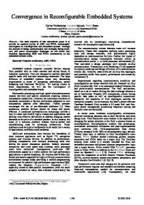
Figure 2: Synthesis results of six benchmark circuits.
the application. The novel architecture, which is based on a 4-bit ripple carry adder that includes configuration memory bits, offers a tradeoff between coarse and fine granularity and can be used for efficient mapping in an application. We also evaluate the implementation efficiency using the newly developed technology mapping tool. The remainder of the present paper is organized as follows. Related research is described in Section 2. Section 3 introduces issues related to implementation efficiency in RLDs. Section 4 describes the VGLC architecture. Section 5 describes the technology mapping method. Section 6 describes the evaluation process and method. Section 7 presents a discussion of the results obtained herein. Finally, the conclusions and an overview of future research are presented in Section 8.
2. Related Research The need to optimize a general-purpose reconfigurable logic cell architecture is recognized in the field of reconfigurable IP-core design. For example, mixed-grain FPGA [5] with four 2-LUTs and carry generation logic is used to reduce critical path delay and implementation area for the DSP application domain. Mixed-grained FPGA can construct a 4bit adder or 4-input logic using one logic cell as well as our concept. They performed implementation evaluation using hand mapping for small circuits. Reference [6] also proposes memory-oriented architecture. Wilton et al. presented a synthesizable datapath-oriented embedded FPGA [7] that is optimized for bus-based operations, which are common in signal processing. This architecture will be used to implement multiply functions, rather than a more general logic circuit. NEC electronics’ DRP-1 [8], Hewlett Packard Chess architecture [9], and IPFLex’s DAPDNA [10] are proposed for DSP application domain. These devices are based on the ALU structure. The function units in Chess are 4-bit ALUs, and the connections are 4-bit buses. Each ALU is adjacent to four switch boxes, and each switch box is adjacent to four ALUs. On the other hand, DPFPGA [11] and the medium-grain logic cell [12] are based on the LUT structure. In [13], the proposed logic cell includes a 6:2 compressor, which features additional fast carry chains that concatenate adjacent compressors and can be routed locally without a global routing network. Altera Stratix devices [14, 15], Xilinx Virtex-5 [16], and Kumamoto University MCNC [17] are multigrained (adaptive) LUT structures. In the StratixII and Stratix-III, the adaptive logic module (ALM) can be used for varying input granularity. Higuchi et al. [18] presented reconfigurable hardware (RHW), which has a 1bit full adder and EXOR and MUX. While they presented a fast depth-constrained technology mapping algorithm for RHW as tree-structured 2-LUTs, RHW only ensures 2-input logic completely. Peter Jamieson and Jonathan Rose present shadow clusters [19]. The shadow cluster is a standard FPGA logic cluster, such as a multiplier, that shares the routing resources with the hard circuit. The key advantage of the shadow cluster concept is that the waste associated with the unused programmable routing is mitigated in hard circuit tiles because a shadow cluster always allows the programmable routing designed for hard circuits to be used.
3. Application Implementation Spectrum 3.1. Granularity Conventional RLDs are roughly classified into fine-grained and coarse-grained architecture types based on the granularity of the basic logic block [20]. The fine-grained reconfigurable architecture is associated with lookup tables (LUTs) or multiplexers, which are essentially identical to the logic elements of FPGAs. These logic elements can efficiently implement any circuit for random logic functions. On the other hand, a typical element of the coarse-grained reconfigurable architecture is a computational datapath unit, such as the arithmetic-logic unit (ALU). This architecture
International Journal of Reconfigurable Computing
3
Table 1: Structures of typical RLDs. Device
Virtex-4 (XC4VLX15) [21] 4-LUT × 8 Carry logic × 2 MULT AND × 8 Distributed RAM 64 bit 112,288 18-bit multiplier
Logic Block structure
# of LBs Dedicated IP
Cin
X
Y
x0
M3
Cout
M2
DRP-1 [8] 8-bit ALU 8-bit DMU Register file (8 bit × 16 word) 512 32-bit multiplier
x1
M1
M2
M3
M0
y0
S
x1
x0
x2
M1
M0
y0
y1
Common part X Y Cin
FA
S Cout
Full adder (coarse grain)
x0 x1
2-CF∗
y0 HC
y1
Hybrid cell (variable grain)
Reed-Muller canonical form (fine grain)
∗ CF:
M Configuration memory bit (a)
x0 x1 x2
y
(b)
Canonical form (c)
Figure 3: Basic structure of a hybrid cell.
type reduces the total amount of configuration data, thereby improving the reconfiguration overhead. NEC electronics’ DRP-1 [8] and IPFLex’s DAPDNA [10] are coarse-grained dynamic reconfigurable processors that are developed for the current market. However, these RLDs can be efficiently implemented only in their specific application domains. If fine-grained RLDs incorporate a digital filter, which requires several arithmetic operations, a large circuit area will be required. On the other hand, coarse-grained RLDs have several area and delay overheads for glue logic implementation. In order to overcome this disadvantage, traditional RLDs have dedicated circuits inside and outside the logic block. Table 1 shows the features of two typical RLDs. The Xilinx Virtex-4 (XC4VLX15) [21] comprises a carry logic, a MULT AND, and an 18-bit multiplier that is embedded as a hard IP core. On the other hand, DRP-1 has an 8-bit data management unit (DMU) as the logic unit and eight 32-
bit multiplier units. However, we must carefully consider the type of functionality for dedicated circuits. If these circuits are not utilized in an application, then the space they take up on the chip is wasted. It is difficult to achieve a balance between the operation speed and area in applications.
3.2. Computational Characterization of Applications In this section, we present a type of application domain analysis. For this purpose, we use six types of OpenCores [22] benchmark circuits that are characterized in terms of three types of application domain: the controller domain, the cryptosystem domain, and the DSP domain. We first synthesize six industrial designs using the Synopsys Design Compiler with ASIC standard cell. Here, we extract the datapath circuit in the form of a macroblock using
4
International Journal of Reconfigurable Computing Table 2: Output logic pattern of the BLE (CP = 0). Four-input variable dt 182/65,536 230/65,536
AS 0 1 Total
Three-input variable ds 24/65,536 24/65,536
dt 120/256 148/256
446/65,536 (0.68%)
dc
dz dx
ds 43/256 43/256 206/256 (80.47%)
d y AS Input Carry
M M M M
HCMem[3:0]
CP M
Function AS dx d y dz
dc
AS
X
Y
1
1
X Y Carry AS
0
X
Y
1
1
X Y
0
X
1
Z
C
Add/ Sub
2RMCF
Out
MUX
Out
X Z
S(SUM) T (Carry out)
C dt
ds
Figure 4: Components and functions of a BLE.
the Synopsys Design Ware library. This allows the extraction of various macroblocks, such as adders, multipliers, and wide-ranging MUXes. Nondetected circuits are categorized as random logic computation circuits. We mapped these designs onto standard cells with a CMOS 0.35-μm library and generated a synthesis report containing the area information for each design. Based on the obtained results, we classified all of the design components into three main groups: random logic, arithmetic functions, and MUXes. Figure 2 shows the information obtained from the area report: Ac97 and Vga are the circuits for the control application domain, aescipher and sha256 are the circuits for the for the cryptosystem application domain, and biquad and Dct are the circuits for the DSP application domain. The graph shows the percentage of the total area taken by each function. Since flip flops are unrelated to the division of random logic or arithmetic logic, they are excluded. The ratio of random logic to arithmetic logic is not constant across different applications. In addition, this shows that the MUX occupies a large area in four circuits and has different input ranges, for example, 2:1MUX, 4:1MUX, and 8:1MUX as indicated by the synthesis report. In [5], a similar analysis and results were presented for the DSP application domain. Hence, it is necessary to effectively implement these computations in a logic block for efficiently mapping of the area. At the same time, we must consider not only the type of computation but also various input ranges.
In the following section, we propose a homogeneous architecture in which, as discussed in Section 3.2, the various functionality requirements must be fulfilled in every logic cell. The potential area overhead is avoided by maximal reuse of existing logic cell resources.
4. Proposed Logic Cell Architecture As mentioned above, since the granularity of a conventional logic cell is fixed, it is difficult to efficiently implement circuits for all applications. This problem can be solved if the computational granularity of a logic cell unit can be changed. We propose a logic cell that has a 4-bit ripple carry adder with a configuration memory bit. In this section, we describe a hybrid cell that is used as the basic element of the VGLC. Next, we introduce a novel logic cell structure and its functions.
4.1. Hybrid Cell The arithmetic computation is based on an adder, and the random logic is expressed efficiently in a “canonical form,” such as a lookup table. Figure 3(a) shows the structure of a 1-bit full adder. Although an OR gate is generally used for the output of the full adder, an EXOR gate can also be used. Figure 3(b) shows the 2-input Reed-Muller canonical form.
International Journal of Reconfigurable Computing
5
MUX9
(CP)
(CP)
MUX4
MUX3
MUX1
MUX2
M
Shift_ctr
AS
Y [0]
Z[0] X[0]
C[0]
Y [1]
Z[1] X[1]
C[1]
Y [2]
Z[2] X[2]
C[2]
Y [3]
Z[3] X[3]
C[3] W[0] W[1] W[2]
CP (CP)
MUX5
Carry_in MUX8
MUX7
HC
MUX6
HC
M CS
HC
HC
MUX11
MUX10 BLE
Carry_out MUX12 T3
S3
T5
T2
S2
T6 T1
S1
T4
T0
S0
Shift_in Output selector + FF(4bit-register)
Shift_out
M 9 O[0]
O[1]
O[2]
O[3]
O[4]
M Configuration memory bit Dedicated Line
Figure 5: Variable grain logic cell architecture.
· 2-CF∗ ×4 · 3-CF×2 · 4-CF×1 · 3-CF×1 & 2-CF×2 ∗ CF:
(a) Arith. Mode
(b) Shift-resistor Mode
Canonical form (c) Random Logic Mode
2-misc∗∗
· · 3-misc · 4-misc · 5-misc · 6-misc ∗∗ Misc:
· 2:1MUX×4 · 4:1MUX×2 · 8:1MUX×1 · 4:1MUX×1 & 2:1MUX×2
Misc. logic
(d) Misc. Logic Mode
(e) Wide-range MUX Mode
Figure 6: Basic function of a VGLC.
The 2-input Reed-Muller canonical form is described by the following equation: F(x0 , x1 ) = {F(0, 0)} ⊕ x0 {F(0, 0) ⊕ F(1, 0)} ⊕ x1 {F(0, 0) ⊕ F(0, 1)} ⊕ x0 x1 {F(0, 0) ⊕ F(0, 1) ⊕ F(1, 0) ⊕ F(1, 1)}. (1)
Each part enclosed by brackets corresponds to a configuration memory bit. This equation can represent the 16 logic patterns with a 4-bit configuration memory as well as a 2-input LUT. Both Figures 3(a) and 3(b) have common parts consisting of EXOR and AND gates. Figure 3(c) shows a hybrid cell (HC) composed of a full adder with four configuration memory bits. The HC can be constructed as either a full adder or a 2-input canonical form according to the computation. In the case of mapping a 1-bit full adder,
6
International Journal of Reconfigurable Computing
W[1]
W[0]
MUX11 W[2]
MUX10
MUX12
M
M
M
M Shift_in
(Shift_cnt) Reg.
Reg.
Shift_cnrl
(Shift_cnt)
(Shift_cnt) Reg.
Reg.
Shift_out (SC)
O[3]
(SC)
O[2]
(SC)
O[1]
M SC O[0]
Figure 7: Output selector part.
there is a logic cell structure having either a 4-LUT with carry logic or two 3-LUTs in the traditional FPGAs. In contrast, an HC requires only four configuration memory bits, thereby reducing the configuration data. Furthermore, to allow increased functionality beyond a 1-bit full adder and 2-input Reed-Muller canonical form, we construct a structure called basic logic element (BLE), as shown in Figure 4. A BLE consists of HCs, MUXes, EXOR, inputs dc, dx, d y, dz; and AS, and outputs dt and ds. Since dc, dx, d y, dz, and AS input variables or clamp to 1/0, a BLE can perform three basic functions; as shown in Figure 4.
4.2. Variable Grain Logic Cell Architecture We propose a VGLC architecture with HC. Figure 5 shows detailed views of the ports in the VGLC. The novel logic block, which has 21 inputs and four outputs with a 27-bit configuration memory, consists of four BLEs and an output selector part. The number of BLEs is determined by two reasons, namely, coarse-grained architecture (e.g., Chess [9] and mixed-grained architecture [5]), which employ nibble bit processing in the logic element and are suitable for extension to 4-, 8-, 16-, 32-, and 64-input ranges. On the other hand, fine-grained architecture uses at least 4-input logic implementation in traditional FPGAs. Therefore, by using a VGLC with four BLEs, the VGLC can implement both nibble bit ALU and 4-input random logic. The signal carry in and carry out terminals are connected directly to the adjoining VGLCs as dedicated lines. The add/sub control signal (AS) and carry selector memory (CP) are entered commonly for all four BLEs. As shown in Figure 6, the VGLC can be programmed to operate in one of five modes: Arithmetic, Shift-resistor, Random Logic, Misc. Logic, or Wide-range MUX Mode.
4.2.1. Arithmetic Mode When a BLE is used as a full adder, the VGLC is composed of a 4-bit ripple carry adder or a subtractor with a carry line between the BLEs. Since the carry path is created via the local interconnection within a logic block, it is propagated at a high speed. We can expand the bit range corresponding to the computation using the dedicated lines carry in and carry out. It is possible to dynamically select the add/sub functions using AS.
4.2.2. Shift Register Mode Figure 7 shows the architecture of the output selector part. The output selector with a 9-bit control memory is composed of a serial-to-parallel 4-bit shift register. In addition to the carry path, the VGLC has a dedicated shift line to increase the shift range.
4.2.3. Random Logic Mode When a BLE is used in the canonical form, the VGLC is composed of a 3-input or 4-input canonical form (3CF or 4-CF) with MUX10-12 (see Figure 5) using the 2input canonical form (with some shared inputs). Since 4LUT is a good implementation in conventional FPGAs, four BLEs are implemented in a single VGLC. In the Random Logic mode, the VGLC can have various canonical forms, for example, four 2-input canonical form, two 3-input canonical form, or one 4-input canonical form, so that suitable BLEs corresponding to the circuit designs can be allocated. Furthermore, the mapping area and the number of configuration memory bits are expected to be improved.
International Journal of Reconfigurable Computing x0 (dc)
x1 x1 x 2 0 (dz) (dx) (d y) (AS)
Carry x2 x1 x0
x1 x0 x2
1 1 0
0 1
Equivalent
0
HCMem[3:0]
CP 0
7
y1
y0 y0 (dt)
y1 (ds)
Figure 8: Example of a three-input misc. logic function.
3-misc
2-CF
Macro block
This block is extracted in synthesis process
3-CF
VGLC-HeteroMap
3-CF
Macro block
3-misc
4-misc
Figure 9: VGLC-HeteroMap.
4.2.4. Misc. Logic Mode It is shown that the VGLC can represent 2-, 3-, and 4input canonical forms. However, this requires an area larger than 2-, 3-, and 4-LUTs, respectively. In order to reduce these overheads, we use the misc. logic (miscellaneous logic) function that applies its gate structure. Since a BLE can be used for a 4-input/2-output module, it can represent the maximum 3- or 4-input logic pattern with 4-bit configuration memory bits. Table 2 depicts the logic pattern that can be expressed at the output of dt and ds in the BLE. K The K-input variable has 22 output logic patterns. Thus, there are 65,536, and 256 patterns in the 4-input and 3-input canonical forms, respectively. For example, since AS = 0 in the 3-input variable, dt and ds are capable of covering 120 and 43 logic patterns, respectively. In total, the misc. logic
function has the ability to represent 80.47% of the 3-input logic patterns. Figure 8 shows an example of 3-input Misc. Logic (3-misc.) usage. Using multiple BLEs, the VGLC can also increase the number of inputs that are expressed. The coverages are 73.6% and 50.3% in the 4-input logic and 5-input logic, respectively, with two BLEs. We can combine a maximum of four BLEs.
4.2.5. Wide Range of Multiplexer Mode In Figure 5, the output of MUXes 2-5 is through the HC, and the BLE is composed of a 2:1 multiplexer. In addition to the MUXes 10–12, which are used to realize the canonical form, a wide range of MUX configurations, such as 4:1 and 8:1, can be implemented.
8
International Journal of Reconfigurable Computing
program VGLC HeteroMap(network) for n := each PI to PO do / ∗ n is node ∗ / min label := ∞; if n equal macro then calculate Label(n) and Cut(n) as macro block; else for # of input for CF and Misc. Logic do calculate Label(n) and Cut(n) as delay and # of inputs; if misc. function then if pattern is mismatch then continue; if Label(n) < min label then min label := Label(n); min cut := Cut(n); end if end for Label(n) := min label; Cut(n) := min cut; end for mapping using selected function; end program Algorithm 1: Pseudocode in random logic mapping.
5. Technology Mapping Method
Carry chain
5.1. Mapping Flow In order to efficiently map the five functions of the VGLC, the datapath circuits (e.g., adder) a or wide-ranging multiplexer (e.g., 8:1 multiplexer) are prepared in advance in the user library for the logic synthesis process. We can extract these circuits as a macroblock during logic synthesis. The remaining circuits are mapped using the Misc. Logic and Random Logic modes.
5.2. VGLC-HeteroMap We need to implement random logic circuits using the VGLC structure. UCLA FlowMap [23] is well known as a FPGA technology mapping algorithm. Although the smallest number in the LUT can be mapped using FlowMap, it targets only homogeneous logic cell structures such as 4-LUT. On the other hand, UCLA HeteroMap [24], which has a delay optimized algorithm, can also map heterogeneous structures, such as the Xilinx XC4K series [25], having a 3-LUT and a 4LUT in one logic block. Since the HeteroMap source code is open to the public [26], we develop the VGLC-HeteroMap, which is a modified HeteroMap. In particular, we add the following two factors. (i) Correspondence to the netlist that contains the macroblock. (ii) Addition of the Misc. Logic mode for random logic mapping. First, since HeteroMap targets single-output LUTs, it must be modified such that the netlist will include a multioutput macroblock. Second, the VGLC has the Misc. Logic mode and the Random Logic mode for random logic mapping. Therefore, we add the Misc. Logic matching process into
6-LUT
T6-LUT T6-LUT = 0.4 ns NB6-LUT = 67 NT6-LUT = 698 (a) 6-LUT with carry chain Carry chain
4-LUT
T4-LUT T4-LUT = 0.2 ns NB4-LUT = 16 NT4-LUT = 196 (b) 4-LUT with carry chain
Figure 10: Homogeneous LUT structures with carry chain.
the VGLC-HeteroMap. The pattern matching of Misc. Logic results in Boolean matching. Debnath and Sasao [27] present an efficient method to check the equivalence of two Boolean functions under permutation of the variables. As a basis
International Journal of Reconfigurable Computing
9 c0 c1 · · · c2n −1 is the binary number representation of f . The subscript 2 is used to denote a binary number. Definition 2. Two functions f and g are P-equivalent if g can be obtained from f by permutation of the variables. f ∼P g denotes that f and g are P-equivalent. P-equivalent functions form a P-equivalence class of functions.
4-LUT
T5-LUT-vir
T4-LUT-vir 4-LUT
Definition 3. The function that has the smallest binary number representation among the functions of a P-equivalence class is the P-representative of that class. Figure 9 shows an example of the mapping process in the VGLC. The pseudocode of the VGLC-HeteroMap with the Misc. Logic mode is given in Algorithm 1.
6. Experimental Methodology T4-LUT-vir = 0.2 ns T5-LUT-vir = 0.46 ns
NBVirtex4 = 35 NTVirtex4 = 424
Figure 11: Heterogeneous LUT structures with carry chain.
6.1. Evaluation Environment and Modeling
T1BLE T4BLE BLE (a) 1BLE T2BLE
In this evaluation, we show the number of logic cells, the logic depth, the area, and the amount of configuration data used to implement benchmark circuits. This section presents a brief description of the environment and the model using the following evaluations.
BLE BLE
BLE
BLE
BLE
BLE
(b) 2BLEs
(c) 4BLEs
T1BLE = 2.4 ns
NBVGLC = 27
T2BLE = 2.5 ns T4BLE = 2.6 ns
NTVGLC = 666
Figure 12: Three components of the VGLC.
of the Boolean matching, they introduced the concept of the P-representative and a breadth-first search algorithm for its quick computation. If two functions have the same Prepresentative, then they match. We use this technique for Misc. Logic pattern matching. Since this method is useful for up to eight of inputs, we assume that Misc. Logic circuits with a maximum of eight inputs (8-misc.) are used with BLEs. The definitions for this initial search is as follows. Definition 1. The minterm expansion of an n-variable function is f (x1 , . . . , xn ) = c0 ·x1 x2 · · · xn ∨ c1 ·x1 x2 · · · xn ∨ c2n −1 ·x1 x2 · · · xn , where c0 , c1 , . . . , c2n −1 ∈ {0, 1}. The binary digit c j is called the coefficient of the jth minterm, the jth coefficient, or simply the coefficient. The 2n bit binary number
We need to fairly compare both the coarse-grained and finegrained types with the VGLC. However, a coarse-grained type logic cell has various structures, and there is no freely available CAD tool. Therefore, the fine-grained logic cell is restricted to three types of LUT-based structure, as shown in Figures 10 and 11. Figure 10(a) shows the 6-LUT, and Figure 10(b) shows a 4-LUT with a carry chain. In addition, Figure 11 shows the heterogeneous LUT structure of Virtex4. The total number of transistors in each logic cell is computed using the cell count suggested in [28, 29]. A 6LUT can be implemented using 67 SRAMs, seven inverters, one EXOR, one flip flop, and 64 2:1MUXes, for a total of 67 × 6 + 7 × 2 + 1 × 10 + 1 × 16 + 64 × 4 = 698 transistors. A 4-LUT can be implemented using 16 SRAMs, five inverters, one EXORs, one flip flop, and 16 2:1MUXes, for a total of 16 × 6 + 5 × 2 + 1 × 10 + 1 × 16 + 16 × 4 = 196 transistors. A Virtex-4 structure can be implemented using 35 SRAMs, five inverters, two EXORs, two ANDs, two flip flops, and 35 2:1MUXes, for a total of 35 × 6 + 5 × 2 + 2 × 10 + 2 × 6 + 2 × 16 + 35 × 4 = 424 transistors. On the other hand, the VGLC has a function based on three types of structure; as shown in Figure 12. The VGLC can be implemented using 27 SRAMs, 12 ANDs, four flip flops, 32 2:1MUXes, and 24 EXORs, for a total of 27 × 6 + 12 × 6 + 4 × 16 + 32 × 4 + 24 × 10 = 666 transistors. Each logic cell is counted as a unit when we evaluate the area. Therefore, the total area of the mapping solution is equal to the total number of logic cells. Such simplification is reasonable because the layout information is not yet available, and the die size of commercial FPGAs is not open. Similar to the area count, the total amount of configuration data is characterized by the product: the number of configuration memory bits per logic cell × the total number
10
International Journal of Reconfigurable Computing
0.35 μm standard cell design ware library
Open core benchmark circuits Logic synthesis Design compiler 2003.03
Lib.
Verilog Format transfer Verilog to BLIF(perl)
BLIF
MCNC benchmark circuits
Technology mapping VGLC-HeteroMap
Net
Lib.
Report
Architecture file misc. logicmatching table
Critical path delay Number of cells
Figure 13: Architecture evaluation flow.
of logic cells. The number of configuration memory bits for each architecture is as follows: VGLC: NBVGLC = 27, comparison logic cell: NB6-LUT = 67, NB4-LUT = 16, and NBvirtex4 = 35. The combination delay of the 4-LUT (NT4-LUT = 0.2 nanoseconds) and heterogeneous LUT (NT4-LUT-vir = 0.2 nanoseconds, NT5-LUT-vir = 0.46 nanoseconds) refers to Xilinx Virtex-4 [21], which is manufactured using 90nm process technology. In addition, 6-LUT (NT6-LUT = 0.4 nanoseconds) refers to Xilinx Virtex-5 [16], which is manufactured using 65-nm process technology. The delay parameters in the typical condition refer to Xilinx ISE. On the other hand, with regard to transistor optimization for the proposed architecture, we perform transistor level design with the Rohm 0.35-μm 3.3 V transistor model and obtain the delay by Synopsys HSpice simulation in the typical condition. Table 3 summarizes the combination delay for each function of the VGLC. Note that although the 0.35-μm process technology is somewhat obsolete. In addition, the placement and routing are not performed because the present research focuses on logic depth and area evaluation for the proposed logic cell. The interconnect cost of such an architecture is not considered herein and will instead be evaluated using an advanced process technology in a future study. Therefore, in this evaluation, we assume that the routing architecture is of the island type.
First, the Verilog RTL netlists of circuits are used as inputs for the synthesis tool Synopsys Design Compiler and are mapped onto the standard cell library. An adder and/or wide-ranging multiplexer is extracted as a macroblock using the DesignWare library. Furthermore, we convert the gatelevel netlist into the BLIF format using perl script, the netlists are mapped using the VGLC-HeteroMap. Second, each comparison logic cell used the above-described netlist and technology mapping tool, as well as the VGLC. Finally, we obtain the mapping delay, the logic depth, and the number of logic cells. In this evaluation, OpenCores [22] circuits and MCNC [30] circuits are chosen as benchmarks. Note that since the MCNC benchmarks are provided in EDIF format, which is almost synthesized, we cannot extract macroblocks.
6.2. Evaluation Flow
7. Results and Analysis
Figure 13 shows the evaluation flow, and the three mapping methods are as follows:
7.1. Effect of Misc. Logic
(A) mapping method using Random Logic mode only,
Table 3: Implementation parameters for VGLC. Function 1-BLE (e.g., 2-CF, 3-misc.) 2-BLE (e.g., 3-CF, 4-misc., 5-misc.) 4-BLE (e.g., 4-CF, 6-misc.)
Tfunc. [ns] 2.4 2.5 2.6
(B) mapping method using (A) + Misc. Logic mode + macro block, (C) mapping method using each comparison logic cell.
We first evaluate effect of misc. logic functions. In this evaluation, five OpenCores circuits and large/medium MCNC
International Journal of Reconfigurable Computing
11
Table 4: Number of logic cells and mapping delay. No. of logic cells
Circuit
(A) 563 430 158 1,855 1,452 4,154 11,590 791 3,499 780
C7552 s5378 C2670 misex3 seq ac97 aes biquad sha256 vga
Mapping delay [ns] (B) 410 262 96 1,667 1,006 2,145 4,633 578 1,719 385
(A) 19.9 14.9 17.3 17.7 17.5 10.1 20.5 25.1 17.7 12.8
(B) 15.4 12.7 12.7 17.5 17.4 7.7 19.9 20.2 14.9 12.7
Table 5: Normalized delay, area, and configuration data. Mapping delay
Circuit
(A) 1.00 1.00 1.00 1.00 1.00 1.00 1.00 1.00 1.00 1.00 1.00
C7552 s5378 C2670 misex3 seq ac97 aes biquad sha256 vga Ave.
4-CF 2.6%
Area (B) 0.77 0.85 0.73 0.99 0.99 0.76 0.97 0.80 0.84 0.99 0.87
(A) 1.00 1.00 1.00 1.00 1.00 1.00 1.00 1.00 1.00 1.00 1.00
3-CF 14.1%
Misc. logic with one BLE 44.9%
Figure 14: Ratio of Misc. Logic (five MCNC benchmarks).
(A) 1.00 1.00 1.00 1.00 1.00 1.00 1.00 1.00 1.00 1.00 1.00
(B) 0.73 0.61 0.61 0.90 0.69 0.52 0.40 0.73 0.49 0.49 0.62
Macro 1.6%
Misc. logic 2-CF with four BLEs 7.9% 12%
Misc. logic with two BLEs 18.5%
Data (B) 0.73 0.61 0.61 0.90 0.69 0.52 0.40 0.73 0.49 0.49 0.62
4-CF 2%
Misc. logic with four BLEs 20%
Misc. logic with two BLEs 36.5%
2-CF 15.7%
Misc. logic with one BLE 24.2%
3-CF 0.1%
Figure 15: Ratio of Misc. Logic (five OpenCores benchmarks).
benchmarks are used. Table 4 shows the results of the number of logic cells and the mapping delay for technology mapping benchmarks. This table compares two conditions, that is, a VGLC that uses only a canonical form function without the misc. logic function (column method “(A)”) and a VGLC that adds the misc. logic function (column method “(B)”). Figures 14 and 15 illustrate the ratio of misc. logic to the total number of logic functions. Note that
five OpenCores benchmarks include macroblock functions. misc. logic functions occupy approximately 75.5% and 80.7% in Figures 14 and 15, respectively. Table 5 shows the mapping delay, the area, and the number of configuration data, which are normalized by each value of (A). Compared to case of CF only, Misc. Logic
12
International Journal of Reconfigurable Computing Table 6: Logic depth, area, and data for different architectures.
Circuit C7552 s5378 C2670 misex3 seq ac97 aes biquad sha256 vga circuit C7552 s5378 C2670 misex3 seq ac97 aes biquad sha256 vga
VGLC Area 273,060 174,492 63,936 1,110,222 669,996 1,428,570 3,085,578 384,948 1,144,854 256,410 4-LUT Area 154,840 124,852 41,748 547,624 468,440 1,115,828 1,833,776 255,192 1,015,476 250,880
Depth 6 5 5 7 7 3 8 18 48 11 Depth 8 6 7 7 7 4 8 26 168 33
Data 11,070 7,074 2,592 45,009 27,162 57,915 125,091 15,606 46,413 10,395
Depth 8 6 7 7 7 4 8 25 88 18
Data 12,640 10,192 3,408 44,704 38,240 91,088 149,696 20,832 82,896 20,480
Depth 6 5 5 7 6 4 7 22 168 33
Virtex-4 Area 167,480 132,288 45,156 592,328 506,680 1,225,996 1,982,624 274,328 1,098,372 272,632 6-LUT Area 316,892 291,066 76,082 1,022,570 1,173,338 1,885,298 4,150,308 442,532 2,228,016 517,916
Data 13,825 10,920 3,728 48,895 41,825 101,203 163,660 22,645 90,668 22,505 Data 30,418 27,939 7,303 98,155 112,627 180,967 398,382 42,478 213,864 49,714
Table 7: Normalized logic depth, area, and configuration data. Circuit C7552 s5378 C2670 misex3 seq ac97 aes biquad sha256 vga Min. Max. Ave.
Depth 1.33 1.20 1.40 1.00 1.00 1.33 1.00 1.39 1.83 1.64 1.00 1.83 1.31
Virtex-4 Area 0.61 0.76 0.71 0.53 0.76 0.86 0.64 0.71 0.96 1.06 0.53 1.06 0.76
Data 1.25 1.54 1.44 1.09 1.54 1.75 1.31 1.45 1.95 2.16 1.09 2.16 1.55
Depth 1.33 1.20 1.40 1.00 1.00 1.33 1.00 1.44 3.50 3.00 1.00 3.50 1.62
improves the critical path delay, the area, and the number of configuration data. The VGLC with misc. logic functions improve one at a maximum of 27% and an average of 13% in mapping delay. Similarly, the area and configuration data improve one at a maximum of 60% and an average of 38%. As a result, Misc. Logic has an effect on the improvement of the circuit performance.
4-LUT Area 0.57 0.72 0.65 0.49 0.70 0.78 0.59 0.66 0.89 0.98 0.49 0.98 0.70
Data 1.14 1.44 1.31 0.99 1.41 1.57 1.20 1.33 1.79 1.97 0.99 1.97 1.42
Depth 1.00 1.00 1.00 1.00 0.86 1.33 0.88 1.22 3.50 3.00 0.86 3.50 1.48
6-LUT Area 1.16 1.67 1.19 0.92 1.75 1.32 1.35 1.15 1.95 2.02 0.92 2.02 1.45
Data 2.75 3.95 2.82 2.18 4.15 3.12 3.18 2.72 4.61 4.78 2.18 4.78 3.43
7.2. Comparison with LUT-Based Architectures Table 6 compares four architectures, that is, the VGLC, the Virtex-4, the 4-LUT, and the 6-LUT using five larger MCNC circuits and five OpenCores circuits (as shown Figure 2). The logic depth, the area, and the number of configuration data are shown in the table. Table 7 shows the performances
International Journal of Reconfigurable Computing normalized by each value of the VGLC. Compared to the Virtex-4 logic cell, the VGLC reduces the logic depth and configuration data by 31% and 55%, respectively, the area increases by 24% on average. Compared to the 4-LUT based logic cell, the VGLC reduces the logic depth and configuration data by 62% and 42%, respectively, while the area increases by 30% on average. Compared to the 6LUT based logic cell, the VGLC reduces the logic depth, the area, and the configuration data by 48%, 45%, and 243%, respectively. In particular, Sha256 and vga show improvements in logic depth of more than three times the other benchmarks. Since the critical path line contains multibit adder circuits as a macroblock part, such as a 32bit adder, the VGLC can be effectively packed using the ALU mode. These circuits have a larger arithmetic logic than the other circuits; as shown in Figure 2. The logic depth and amount of configuration data are reducible in all comparative logic cells. For this reason, the misc. logic function and heterogeneous mapping may have a considerable effect on large-scale applications in particular. With fewer logic cells to cross, the routing delay between the modern FPGA is lower. Therefore, it is necessary to pack more logic into one block in order to avoid routing delay, which is a major problem in the deep submicron FPGA. It is important that the VGLC can pack more logic per logic cells. On the other hand, Table 7 shows that most benchmarks occupy more silicon area, as compared to 4-LUT and Virtex-4 architectures. Nevertheless, the configuration data required by the VGLC is less than that required by all three architectures. In the present evaluation, we assume that the routing architecture is island style routing. It is actually a routing area which dominates a die area and has a significant influence on circuit performance (area, delay, and power). However, since the VGLC is used as a logic IP core for small or medium circuits, we believe that the number of routing tracks in island style routing is reduced to below the number of stand-alone type modern FPGAs. Moreover, the VGLC does not restrict the routing architecture to the above style, and various connections and routing architectures can be implemented due to the specifications. For example, Runesas MX-core [31] has massive data banks that consist of SRAM data registers, and the medium-grain reconfigurable architecture [32] has a H-tree routing architecture.
8. Conclusions In the present paper, we have proposed a VGLC architecture and evaluated the area, delay, and configuration data using a technology mapping tool called VGLC-HeteroMap. The novel architecture, which is based on a 4-bit ripple carry adder that includes configuration memory bits, offers a tradeoff between coarse and fine granularity and can be used for efficient mapping in an application. In our evaluation, the VGLC improves the logic depth by 31% and reduces the number of configuration data by 55% on average, compared to the Virtex-4 logic cell. The present study did not consider the routing network, which is likely to dominate the area and delay in an
13 FPGA implementation. In the future, we will study the connection block and routing structure required to best support the VGLC. Currently, we are attempting to optimize the full custom design to evaluate the chip performance and are developing clustering, place, and routing tools for the proposed architecture. Furthermore, the VGLC can be used as an IP core and can be considered as an FPGA logic element. Since the VGLC can reduce the logic depth compared to other traditional LUT architectures, it is possible to implement the VGLC as a 2D array of the VGLC that is connected by an island style routing architecture. Kuon and Rose [33] showed that the benefit of the IP core in the FPGA could be lost due to its fixed position in the chip, whereas the VGLC has no such restriction. We must also estimate the routing resources using [34] and further explore the use of the VGLC.
Acknowledgments The present study was supported by the VLSI Design and Education Center (VDEC) at the University of Tokyo in collaboration with Synopsys, Inc., Calif, USA.
References [1] Y. Satou, M. Amagasaki, H. Miura, et al., “An embedded reconfigurable logic core based on variable grain logic cell architecture,” in Proceedings of International Conference on Field Programmable Technology (ICFPT ’07), pp. 241–244, Kitakyushu, Japan, December 2007. [2] R. Yamaguchi, M. Amagasaki, K. Matsuyama, M. Iida, and T. Sueyoshi, “A novel variable grain logic cell architecture with multifunctionality,” in Proceedings of IEEE Region 10 Annual International Technical Conference (TENCON ’07), pp. 1–4, Taipei, Taiwan, October-November 2007. [3] M. Amagasaki, R. Yamaguchi, K. Matsuyama, M. Iida, and T. Sueyoshi, “A variable grain logic cell architecture for reconfigurable logic cores,” in Proceedings of the 17th International Conference on Field Programmable Logic and Applications (FPL ’07), pp. 550–553, Amsterdam, The Netherlands, August 2007. [4] M. Amagasaki, T. Shimokawa, K. Matsuyama, et al., “Evaluation of variable grain logic cell architecture for reconfigurable device,” in Proceedings of IFIP International Conference on Very Large Scale Integration (VLSI-SoC ’06), vol. 2, pp. 198–203, Nice, France, October 2006. [5] K. Leijten-Nowak and J. L. van Meerbergen, “An FPGA architecture with enhanced datapath functionality,” in Proceedings of ACM/SIGDA International Symposium on Field Programmable Gate Arrays (FPGA ’03), pp. 195–204, Monterey, Calif, USA, February 2003. [6] K. Leijten-Nowak and J. L. van Meerbergen, “Embedded reconfigurable logic core for DSP applications,” in Proceedings of 12th International Conference on Field-Programmable Logic and Applications (FPL ’02), pp. 89–101, Montpellier, France, September 2002. [7] S. J. E. Wilton, C. H. Ho, P. H. W. Leong, W. Luk, and B. Quinton, “A synthesizable datapath-oriented embedded FPGA fabric,” in Proceedings of the 15th ACM/SIGDA International Symposium on Field Programmable Gate Arrays (FPGA ’07), pp. 33–41, Monterey, Calif, USA, February 2007.
14 [8] H. Amano, A. Jouraku, and K. Anjo, “A dynamically adaptive hardware on dynamically reconfigurable processor,” IEICE Transactions on Communications, vol. E86-B, no. 12, pp. 3385– 3391, 2003. [9] A. Marshall, T. Stansfield, I. Kostarnov, J. Vuillemin, and B. Hutchings, “A reconfigurable arithmetic array for multimedia applications,” in Proceedings of ACM/SIGDA International Symposium on Field Programmable Gate Arrays (FPGA ’99), pp. 135–143, Monterey, Calif, USA, February 1999. [10] T. Sugawara, K. Ide, and T. Sato, “Dynamically reconfigurable processor implemented with IPFlex’s DAPDNA technology,” IEICE Transactions on Information and Systems, vol. E87-D, no. 8, pp. 1997–2003, 2004. [11] D. Cherepacha and D. Lewis, “DP-FPGA: an FPGA architecture optimized for datapaths,” VLSI Design, vol. 4, no. 4, pp. 329–343, 1996. [12] J. G. Delgado-Frias, M. J. Myjak, F. L. Anderson, and D. R. Blum, “A medium-grain reconfigurable cell array for DSP,” in Proceedings of the IASTED International Conference on Circuits, Signals, and Systems (CSS ’03), pp. 231–236, Cancun, Mexico, May 2003. [13] H. Parandeh-Afshar, P. Brisk, and P. Ienne, “A novel FPGA logic block for improved arithmetic performance,” in Proceedings of the 16th International ACM/SIGDA Symposium on Field Programmable Gate Arrays (FPGA ’08), pp. 171–180, Monterey, Calif, USA, February 2008. [14] Altera, Inc., Altera Stratix II Data Sheet, 2005. [15] Altera, Inc., Altera Stratix III Data Sheet, 2007. [16] Xilinx, Inc., Xilinx Virtex-5 Data Sheet, 2007. [17] M. Iida and T. Sueyoshi, “A shape evaluation of circuit area for reconfigurable logic device,” in Proceedings of International Technical Conference On Circuits/System, Computers and Communications (ITC-CSCC ’03), vol. 3, pp. 1595–1598, KangWon, Korea, July 2003. [18] T. Higuchi, M. Iwata, D. Keymeule, et al., “Development of adaptive device,” in Proceedings of IEICE General Conference, vol. A-3-14, p. 100, Kyoto, Japan, March 1998. [19] P. Jamieson and J. Rose, “Enhancing the area-efficiency of FPGAs with hard circuits using shadow clusters,” in Proceedings of IEEE International Conference on Field Programmable Technology (FPT ’06), pp. 1–8, Bangkok, Thailand, December 2006. [20] T. Sueyoshi and M. Iida, “Configurable and reconfigurable computing for digital signal processing,” IEICE Transactions on Fundamentals of Electronics, Communications and Computer Sciences, vol. E85-A, no. 3, pp. 591–599, 2002. [21] Xilinx, Inc., Xilinx Virtex-4 Data Sheet, 2006. [22] Opencores org, http://www.opencores.org/. [23] J. Cong and Y. Ding, “Flowmap: an optimal technology mapping algorithm for delay optimization in lookup-table based FPGA designs,” IEEE Transactions on Computer-Aided Design of Integrated Circuits and Systems, vol. 13, no. 1, pp. 1– 12, 1994. [24] J. Cong and S. Xu, “Delay-oriented technology mapping for heterogeneous FPGAs with bounded resources,” in Proceedings of IEEE/ACM International Conference on Computer-Aided Design (ICCAD ’98), pp. 40–45, San Jose, Calif, USA, November 1998. [25] Xilinx, Inc., Xilinx XC4000 Data Sheet, 1999. [26] UCLA CAD-LAB, http://cadlab.cs.ucla.edu/. [27] D. Debnath and T. Sasao, “Fast Boolean matching under permutation by efficient computation of canonical form,” IEICE Transactions on Fundamentals of Electronics, Communications
International Journal of Reconfigurable Computing
[28]
[29]
[30]
[31]
[32]
[33]
[34]
and Computer Sciences, vol. E87-A, no. 12, pp. 3134–3140, 2004. J. Cong and H. Huang, “Technology mapping and architecture evaluation for k/m-macrocell-based FPGAs,” ACM Transactions on Design Automation of Electronic Systems, vol. 10, no. 1, pp. 3–23, 2005. Y. Hu, S. Das, S. Trimberger, and L. He, “Design, synthesis and evaluation of heterogeneous FPGA with mixed LUTs and macro-gates,” in Proceedings of IEEE/ACM International Conference on Computer-Aided Design (ICCAD ’07), pp. 188– 193, San Jose, Calif, USA, November 2007. K. McElvain, “IWLS’93 benchmark set: version 4.0,” in Proceedings of MCNC International Workshop on Logic Synthesis (IWLS ’93), Tahoe City, Calif, USA, May 1993. K. Mizumoto, T. Tanizaki, S. Kobayashi, et al., “A multi matrixprocessor core architecture for real-time image processing SoC,” in Proceedings of IEEE Asian Solid-State Circuits Conference (ASSCC ’07), pp. 180–183, Fukuoka, Japan, November 2007. M. J. Myjak and J. G. Delgado-Frias, “A medium-grain reconfigurable architecture for DSP: VLSI design, benchmark mapping, and performance,” IEEE Transactions on Very Large Scale Integration (VLSI) Systems, vol. 16, no. 1, pp. 14–23, 2008. I. Kuon and J. Rose, “Measuring the gap between FPGAs and ASICs,” IEEE Transactions on Computer-Aided Design of Integrated Circuits and Systems, vol. 26, no. 2, pp. 203–215, 2007. W. M. Fang and J. Rose, “Modeling routing demand for early-stage FPGA architecture development,” in Proceedings of the 16th International ACM/SIGDA Symposium on Field Programmable Gate Arrays (FPGA ’08), pp. 139–148, Monterey, Calif, USA, February 2008.