Dynamically Reconfigurable Embedded Image Processing System Jim Nichols and Sandeep Neema Institute for Software Integrated Systems (ISIS), Vanderbilt University Nashville, TN 37325, U.S.A
[email protected] [email protected]
Abstract ? Image processing uses many data processing techniques to transform the raw data or information from a sensor system into useful information from which decisions can be made. Historically, the data processing systems associated with each image processing application were tuned or optimized to that application such as machine inspection, pattern recognition, etc. In today's environment it is desirable to quickly evaluate promising techniques while maintaining minimal manpower and/or capital penalties. In this paper we will describe the implementation of a Missile Automatic Target Recognition (ATR) based on Adaptive Computing Systems (ACS) / Model Integrated Computing (MIC) techniques developed at ISIS/Vanderbilt University. 1. Introduction Embedded image processing systems and specifically embedded missile ATR systems face many challenges, due to extremely large computational requirements and other physical, power, and environmental constraints. Image sizes can be large with a high frame rate that may vary from 30Hz up to over 300Hz. For mission critical processing of this input data must meet hard realtime requirements. In order to achieve these requirements many processing components must be implemented in hardware; other components may be implemented in software on embedded processors such as Digital Signal Processors (DSPs). Fielded ATR systems also require special attention to power consumption, and heat and This project is a DARPA/ITO Adaptive Computing Systems funded effort, involving close cooperation with US ARMY/AMICOM.
space constraints. During some processing modes it is desirable to put components not needed to meet processing requirements at that time into a low power or shut down mode.? Also, these ATR systems must be physically small, typically less than 0.5 cubic foot volume, and lightweight. These factors require that component utilization be maximized as much as possible for selected hardware. During the course of the flight of the missile, as its environment changes (ex. altitude and distance to target) processing requirements also change (see figure 1). A dynamically reconfigurable implementation offers the chance to address these challenges with architectures that change in response to the changing environment. Hardware architectures are required that can structurally adapt, adjusting themselves for each mode of operation to achieve high performance with the changing algorithms. This high performance is made possible due to the advances in reconfigurable device technology (Field Programmable Gate Arrays).
Figure 1: Adaptive ATR Scenario
2. Design Environment Designing such systems poses a major challenge to the design engineering process, mandating the use of advanced design techniques. The ACS design environment [1] developed at ISIS/Vanderbilt University offers such an advanced design tool. The "programming interface" consists of a high-level, graphical specification environment which runs on a Windows PC (NT or 9x). The user specifies the computations to be performed by drawing a graphical data flow representation consisting of boxes (algorithms) and interconnecting lines (communications) (figure 2). The performance requirements of the application and the topology of the available hardware network are also specified graphically.
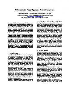
3. ATR Algorithm The complexities of the changing computational support requirements and dynamic constraints associated with the ATR algorithm are a good test of the ACS environment. The ISIS/Vanderbilt ACS environment was used for design, implementation, and mission adaptation of the missile ATR problem. The ATR algorithm is based on correlation filtering [2]. Each image of the input image stream is sequentially preprocessed then transformed into the frequency domain. The copies of this spectral image are then multiplied in parallel by the filter correlation matrices for the three classes of targets of interest. The results for each of the three classes are then inverse frequency domain transformed to give the correlation surface maps associated with each of the three classes. The strongest correlation peaks for each image class are compared with the reference classes to yield the class closeness measures. These measures are used to determine the class for the object in the image associated with the correlation peaks. Note that all operations after the forward frequency domain transform can be parallelized for each class. The flow diagram of this algorithm is shown in figure 3. Class Filter Banks
Figure 2: Graphical Model Editor (GME) The ACS tools look at the graphical specifications and the underlying hardware resources and present the user with many optimized configurations to choose from for the final system implementation. The final generated system implementation consists of executable / synthesizable code and architecture and interface specifications for the underlying ACS run-time environment described. In addition to implementing data flows made up of standard image processing algorithms, the user can also expand the functionality of the design tools by adding new algorithms to the support library. The algorithms are implemented as normal “C" subroutines for the DSP’s and as VHDL for the FPGA’s and are fully integrated into the system by specifying pertinent information in terms of an algorithm model.
Input Image Stream
Preprocessing
2D FFT
Multiply
2D IFFT
Class Distance Calculation
Class Determination
Display Result
Figure 3: ATR Flow Diagram 4. ACS Implementation of ATR Algorithm The solution of this problem involves first creating a model of the algorithm processing. If viewed from a hierarchical point of view, the top most layer corresponds to top level flow diagram of the algorithm. As seen in figure 4, five of the algorithm blocks where merged when making the model for the ATR algorithm. The blocks associated with the aft portion of the dataflow processing pipeline can be parallelized for each class being evaluated. Class Filter Banks
Input Image Stream
Preprocessing
2D FFT
Multiply
do_peaks
2D IFFT
Class Distance Calculation
Class Determination
Display Result
Figure 4: ATR Model Flow Diagram Each block in this top-level diagram is then
broken down into its own hierarchical tree to increasing levels of details. This allows both the overall flow of the algorithm to be observed as well as the details of any individual element. The topmost layer in shown in figure 5. Notice that it’s representation is very similar to the data flow of the ATR algorithm.
captured in the structural model as a constraint or attribute. Specific implementations can also be defined and required for performance purposes. Intercommunication bandwidths and communication / data routing constraints can also be specified at the element level (figure 7).
Figure 7: Constraint definitions Figure 5: Top Level Model of ATR Algorithm Each element of this model has it own hierarchy in the modeling environment. An example of this hierarchy is shown in figure 6. The “do_peaks” element or icon in the top level model or graph represents the model associated with the next layer down (figure 6, top right). The “matched_filter” model icon or element in the top right model graph represents the model in the lower left portion of figure 6. The “corstats” model icon in the lower left model represents the model in the lower right quadrant of figure 6, and so on.
Figure 6: Model Hierarchy Example As the more detailed lower layers of the model are defined, additional information can be placed in the model. Based on analysis and other factors, attributes and constraints may be added to the elements of these models. For example, if from analysis it is determined that a minimum of single precision IEEE floating point accuracy is needed to satisfy the ATR accuracy criteria, this can be
The dataflow-like model hierarchy just discussed refers to the structural modeling aspect of the ACS modeling environment. There are two other aspects: the behavior and the resource models. The behavioral modeling aspect describes how the system will perform based on operational states, events, and transitions [1]. This allows for the specification of how the system should react based on events or transitions (figure 8).
Figure 8: Behavioral Model Example As with all the model aspects in the ACS environment, the behavioral model supports hierarchy. Figure 9 shows the more detailed model of the missile system “ready” state.
system to implement the problem defined in the models.
Figure 9: Ready Behavioral Model Example Some examples of behaviors that would be modeled in this aspect are shown in figure 1. For example, if the target lock on was lost after launch of the missile and the target needed to be reacquired. Another example would be the reacquisition of a target when the ATR system discovered it is locked onto the wrong target (ex. civilian or friendly target). By capturing how the system should behave in response to various events and stimuli, the designer can ensure proper operation of the system under various conditions. The third aspect to the modeling environment is the resource model. It describes what resources are available to implement the solution to the problem described in the structural model. It provides the model interpreter with the details or constraints of the available computational hardware resources (figure 10). In this example, the resources model contains a host computer system, a digital signal processor, and a field programmable gate array. Various resource models can allow the design to be implemented on a simple prototype system to more complex deliverable systems based on the target resources available.
The ATR system described above has been implemented in software on a homogeneous network of TI TMS320C40 digital signal processors. Efforts are now underway to migrate to a custom heterogeneous computing platform consisting of configurable hardware (Xilinx/Altera FPGA’s) and DSP’s (Texas Instruments C40’s). On this heterogeneous platform the modeling environment will assign portions of the algorithm based on computational complexity, user timing constrains, and available resources to the most appropriate portion of the platform to satisfy these constraints. 5. Conclusions Using the ACS environment and tools has greatly simplified the task of generating an implementation of this complex algorithm. It also has allowed easy adaptation & inclusion of new hardware elements to improve the system performance. While this paper focused on an ATR problem, this technology can be applied to many other image processing problems. Previous work in MIC based image processing systems has shown great promise [4,5]. The movement from a homogeneous DSP only architecture to heterogeneous DSP/FPGA architectures will provide a much better cost / performance ratio. The ACS environment and tools will greatly facilitate this transition. 6. References [1] Sandeep Neema, Ted Bapty, Jason Scott, “Development Environment for Dynamically Reconfigurable Embedded ACS Tools Systems”, International Conference on Signal Processing Applications and Technology (ICSPAT99), Orlando, Florida.
Figure 10: Resource Model Example The ACS model interpreter utilizes all three modeling aspects as guidance or constraints to arrive at the best solution of the problem based on those constraints. The ACS development environment [2] coupled with the appropriate runtime environment [3] generate a solution
[2] A. Mahalanobis, B.V.K. Vijaya Kumar, and S.R.F. Sims, “Distance-classifier correlation filters for multi-class target recognition”, APPLIED OPTICS, Vol. 35, No. 17, pp3127-3133, 10 June 1996. [3] Jason Scott, Ted Bapty, Sandeep Neema,” Runtime Environment for Dynamically Reconfigurable Embedded Systems”, International
Conference on Signal Processing Applications and Technology (ICSPAT99), Orlando, Florida. [4] Moore, M.: "A DSP-Based Real-Time Image Processing System," Proceedings of the 6th International Conference on Signal Processing Applications and Technology (ICSPAT95), Boston, MA, August, 1995. [5] Nichols J., Moore M. S.: "An Adaptable, Cost Effective Image Processing System", Proceedings of the 10th JANNAF Non-destructive Evaluation Sub Committee, Salt Lake City, UT, March, 1998