TR-IIS-08-005
An Embedded Workflow Framework for Flexible Robotic Devices
T. S. Chou, S. Y. Chang, Y. F. Lu, Y. C. Wang, M. K. Ouyang, C. S. Shih, T. W. Kuo, J. S. Hu and J. W. S. Liu
Apr. 21, 2008
||
Technical Report No. TR-IIS-08-005
http://www.iis.sinica.edu.tw/page/library/LIB/TechReport/tr2008/tr08.html
Institute of Information Science, Academia Sinica Technical Report TR-IIS-08-005
An Embedded Workflow Framework for Flexible Robotic Devices T. S. Chou, S. Y. Chang, Y. F. Lu, Y. C. Wang, M. K. Ouyang, C. S. Shih, T. W. Kuo, J. S. Hu and J. W. S. Liu ABSTRACT This paper describes the design and implementation of an open source embedded workflow framework (EMWF). By providing a language for specifying embedded workflow processes and light weight engines for executing and managing them, EMWF enables us to design and build service robots and assistive robotic devices on workflow-based architecture. The embedded process definition language supported by EMWF is called SISARL-XPDL. It is a subset of the standard process definition language XPDL (XML Process Definition Language) augmented with elements that are essential for smart embedded devices but not offered by XPDL. The SISARL-XPDL preprocessor translates augmented elements into either directives for the engine or compound built-in activities defined in terms of standard XPDL. EMWF provides two workflow engines, for Linux and Windows CE platforms. Both are written in C in order to keep the memory footprint and runtime overhead of the engine small. We use EMWF as a test bed for experimentation with the workflow approach and evaluation of workflow-based design.
Copyright @ April 2008
T. S. Chou, Y. C. Wang, and J. W. S. Liu are affiliated with Institute of Information Science, Academia Sinica.Taiwan. Their email addresses are {tschou, wych, janeliu}@iis.sinica.edu.tw S. Y. Chang, M. K. Ouyang, Y. F. Lu, C. S. Shih and T. W. Kuo are affiliated with Department of Computer Science and Information Engineering, National Taiwan University, Taiwan. M. K. Ouyang’s email address is
[email protected], and the email addresses of Y. F. Lu, C. S. Shih and T. W. Ku are {d93023, cshih, ktw}@csie.ntu.edu.tw J. S. Hu is affiliated with Electrical and Control Engineering Department, National Chiao-Tung University, Taiwan. His email address is
[email protected]
1
TABLE OF CONTENTS ABSTRACT............................................................................................................................ 1 TABLE OF CONTENTS ........................................................................................................ 2 1 INTRODUCTION ............................................................................................................... 3 2 RELATED WORKS ............................................................................................................ 5 3 ARCHITECTURE AND COMPONENTS.......................................................................... 6 3.1 Application Structure .................................................................................................. 6 3.2 Engine Structure.......................................................................................................... 9 4 WORKFLOW MANAGER AND PROCESSOR.............................................................. 10 4.1 Design Rationales ..................................................................................................... 10 4.2 Activity Execution .................................................................................................... 12 4.2.1 Linux Version................................................................................................. 13 4.2.2 Windows CE Version ..................................................................................... 13 5 SISARL-XPDL .................................................................................................................. 15 5.1 Subset of XPDL Elements ........................................................................................ 15 5.2 Built-ins for Behavior Coordination ......................................................................... 17 6 CASE STUDIES................................................................................................................ 18 6.1 Memory and Run-Time Overheads........................................................................... 19 6.2 Usage and Effectiveness ........................................................................................... 20 7 SUMMARY ....................................................................................................................... 22 8 ACKNOWLEDGMENT.................................................................................................... 22 8 REFERENCES .................................................................................................................. 22
2
1 INTRODUCTION In coming decades, we are likely to witness accelerated growth in diversity and use of service robots and assistive robotic devices (SRARD). Examples include home and personal automation and assistive devices (e.g., robotic housekeeping aids and mobility assistants [1-5]) and social and service robots (e.g., robotic pets, object fetchers and intelligent physical-therapy companions [6-9]). Such devices can help to improve the quality of life and enhance the accessibility and mobility of their users, make physical exercises and therapy regiment more effective, and so on. They have become increasingly more essential tools, as world population ages and more and more elderly individuals need their help to stay well and remain independent. SRARD also include automation equipment and tools for hospitals and other care-providing institutions (e.g., [10-11]). Their use is a way to improve quality and reduce the costs of health and medical care. Despite vast differences in their functions and appearances, SRARD share many common characteristics and requirements. Typically, these devices are used at their users’ discretion, and often for the purpose of complementing and compensating users’ skills and weaknesses [12, 13]. Such a device must be affordable, easy to use. It must be flexible, meaning that it is configurable, customizable and can adapt: It can be easily configured to work with a variety of sensors and devices, rely on different support infrastructures and operate in different environments. It should be customizable according to its user’s preferences. The device may be in use for many years and, hence, should be able to adapt to changes in its user’s needs, mindset and skills. Advances in robotic and assistive technologies have made almost all essential SRARD functions and numerous advanced features feasible. The technology for their design and implementation is still relatively immature, however. Even today, all but the simplest SRARD devices are handcrafted. Once built, to configure and customize them is often difficult. This fact has motivated us to develop the open source embedded workflow framework (EMWF) described in this paper. Its primary purpose is to reduce the levels of expertise and effort (and consequently the cost) required for the design and implementation of easily configurable and customizable smart SISARL devices [14] in general and behavior-based SRARD in particular from reusable components. As its name implies, EMWF is based on the try-and-true workflow approach [15] that is widely used in enterprise computing for automation of business processes. The components of an application based on this approach are workflows, each of which is composed from elementary steps called general activities (or simply activities). In workflow-based embedded devices such
3
as SRARD, some activities are done with executable code; others are carried out manually or by hardware components. The order and conditions under which activities in a workflow are executed, the resources needed for their execution, and interactions among activities are specified in terms of a workflow graph: In essence, it is an executable control and data flow graph. Each node in it represents an activity. Each directed edge represents a transition from the source activity to the sink activity, and consequently a precedence relation between the activities. Each workflow has a
start
and one or more
stop.
They are special activities that have no
predecessor and successor, respectively, in the graph. A key element of a platform for workflow applications is the workflow engine (or engine for short). This middleware offers the applications an execution environment. In addition to executing activities implemented by software components, the engine also provides and executes built-in activities that start and stop workflows, and once a workflow starts, sequence, synchronize and coordinate general activities in it as specified by the graph defining the workflow. By managing control and data flows among general activities and allocating resources and enforcing policies for them on behalf of the applications, the engine dynamically integrates the application components. A reason for the wide adoption of workflow approach for automation of business processes is the relative ease with which workflow-based applications can be designed and implemented. The developer of such an application only needs to supply the components that implements activities and workflow graphs that specify the interconnection and interaction among activities. One can configure and customize the application by changing the workflow graphs in it and by using different components for activities in the graphs. Existing standard process definition and execution languages (e.g., [16 - 19]), together with tools for defining and editing workflow definitions in diagram and text forms, and for parsing and building them significantly reduce the effort to do these tasks. They enable business application experts to develop and customize complex automatic business processes easily themselves without help from IT experts. EMWF enables us to adopt the workflow-based architecture for SRARD by providing a language for the specification of embedded workflow applications and choices of light-weight engines for executing and management them on embedded platforms. Specifically, the workflow process definition language supported by EMWF is called SISARL-XPDL. It is a variant of the standard XPDL (XML Process Definition Language) [18]. EMWF provides two versions of workflow engines for Linux and Windows CE. Both are written in C in order to keep the
4
memory footprint and runtime overhead introduced by the engine small. We are using EMWF as a test bed for the experimentation with the workflow paradigm and evaluation of its effectiveness, merits and shortcomings. Following this introduction, Section 2 provides an overview of closely related work. Section 3 describes the major components of EMWF and general structure of embedded devices built within the framework. Section 4 describes the design, architecture and implementation of the engine software. Section 5 describes the entities and elements of SISARL-XPDL and provides rationales for their inclusion. Section 6 describes the case studies done to date. Section 7 summarizes the paper and presents future work. 2 RELATED WORKS As stated earlier, SISARL-XPDL is a small variant of standard XPDL [16]. XPDL was developed by WfMC (Workflow Management Coalition) to standardize specifications of workflows and thus, make process definitions interchangeable among modeling tools and execution engines. SISARL-XPDL contains a subset of XPDL, leaving out most of the entities and elements in standard XPDL that are not needed for embedded applications. The subset is augmented with elements essential for SRARD but not provided by standard XPDL. The SISARL-XPDL preprocessor translates some augmented elements into attributes of activities and workflows. The engine treats them as scheduling and resource allocation directives. Other augmented elements are built-in activities (e.g., behavior coordination mechanisms). They are translated into compound built-in activities defined by workflow graphs in terms of standard XPDL. In this way, we minimize the impact of incompatibility between SISARL-XPDL and standard XPDL. Similarly, numerous modern workflow engines and management environments (e.g., [20 - 22]) are available. Many of them handle in an integrated way automated activities implemented in software, activities triggered by external events, and activities carried out manually. EMWF is built on the foundation established by them. Existing engines are designed to run in J2EE or .NET environments and require resources far exceed amounts available in SRARD and similar embedded devices. In contrast, the EMWF engines are scaled down to fit embedded platforms. EMWF has the same goal as many efforts by robotic community aiming at making the creation and modification of robotic and assistive device software and systems easier. As examples, building blocks and development environments provided by Microsoft Robotic Studio and LEGO®MINDSTORMS™ reduce the skills and effort that are required to design and build some 5
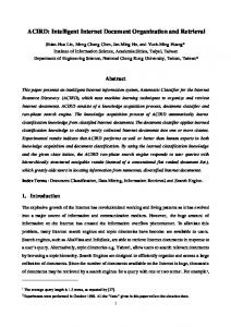
robots [23, 24]. Research projects such as CARMENO, CLARAty, MARIE, MIRO, ORCA, OROCOS, and Player [25-31] aim to provide component-based software architectures and tools for building robotic software systems from reusable modules. EMWF aims to further the goal of Embedded Software Architecture for Intelligent Robots (ESAIR) [32]. ESAIR is an object-oriented environment designed and developed to support component-based design and implementation of embedded software of behavior-based robots. By providing a pluggable component interface and a discovery mechanism, ESAIR enables devices and software modules to be plugged in and removed from the system without having to redesign and implement the robot. Many design choices of EMWF were directly influenced by ESAIR. 3 ARCHITECTURE AND COMPONENTS This section first describes architecture of workflow-based embedded devices focusing on the applications. It then describes the system from the perspective of the workflow engine. 3.1 Application Structure In a SRARD device with workflow-based architecture, most parts are built from activities and workflows. Drivers and event handlers of some components may be hardwired, however. To illustrate, Figure 1 shows the structure of a representative workflow-based SRARD, highlighting its application components. The device is an intelligent medication cart designed to lead its user to patients and assist the user in administration of medications. The cart has microcontrollers and motors for propulsion, ultrasound range finder and other sensors for guidance and navigation, RFID reader and bar-code scanner for identification, and so on. Their drivers, like the workflow engine itself, are not built from workflows; these parts are shown in dark color in the figure. The other functions, including guidance and propulsion, are provided by workflows. In general, a device may contain both non-embedded and embedded workflows. For example, intelligent medication carts typically support planning and scheduling medication administration and automatic patient record updates. These components have no embedded modules. Their workflows are executed just like workflows in enterprise applications, perhaps even by another engine, not the embedded engine. We will ignore non-embedded workflows hereafter. By workflows, we mean embedded workflows.
6
Scheduler and planner Dispenser control Navigation Guidance and propulsion
Edge Edge
Sense Sense edge edge
20Hz
on edge? Yes Sense Sense contact contact
Contact Contact
10Hz
contacted?
No
No Yes Check Check the the route route
Track Track
2Hz
Drivers and event handlers
Environment Interaction
No
on route? Yes
Command Command the the cart cart to to move move
Workflow engine OS kernel
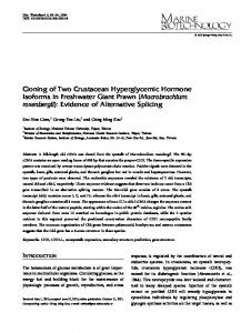
Figure 1. Structure of a workflow-based device Figure 2 shows the guidance and propulsion module of the cart in its entirety to illustrate a distinguishing characteristic of embedded workflows: Only some activities in the module are executed by the engine on a CPU; we will call them software activities when we need to be specifics. An embedded workflow also has external activities: They are carried out manually, or by sensor devices, special-purpose hardware, and mechanical parts. In our example, external activities are in dotted boxes labeled environment interaction and cart components.
Sense Sense edge edge
Edge Edge 20Hz
On edge?
No Yes
Contact Contact 10Hz
Follow Follow edge edge
Sense Sense contact contact contacted?
No Yes
Track Track 2Hz
Check Check the the route route
Back & & random random Back move move (Contact maneuver) maneuver) (Contact
No
on route?
Track Track maneuver maneuver
Yes
Command Command the the cart cart to to move move Environment Interaction
(Edge maneuver) maneuver) (Edge
Workflows
Move the the cart cart Move Cart Components
Figure 2. Guidance and propulsion workflows
7
In this and subsequent workflow graphs, we use rectangular boxes to represent general activities of the application. Table 1 lists examples of built-in activities. The left column lists generic built-ins required by typical embedded applications, including
start, stop, listen, if else
and
merge
(implicitly indicated by multiple edges directed to a single activity in order to save space) shown in Figure 2. The right column lists built-in activities EMWF provides specifically for behavior-based robotic applications. We will return to discuss these choices in Section 5. The symbols used to represent generic built-ins are from Windows Workflow Framework [22]. When there is no need to be specific, we use dotted circles to represent all built-in activities Table 1 Examples of built-in activities Built-ins for BCA
Generic built-ins Start
A
Arbiter
Repeat point
V
Voter
While
S
Superposition
If else Delay /Timeout
P
Push data
Stop
R
Pull data
+
Throw
Mode change
Exception -
Invoke workflow Execute workflow Invoke component command Listen component event
Before moving forward to describe engine structure, it is important to note that procedures and executables for general software activities must not make blocking calls, and each has a single entry and a single exit. In essence, all activities that alter the flow path of a workflow are built-ins. This requirement is not unduly restrictive for embedded workflows as exemplified by the module in Figure 2. In behavior-based robotic devices, such as the ones targeted by ESAIR [32], activities are behaviors. With one exception, they meet this requirement naturally. The exception is when behaviors share sensor devices; a behavior needs to send the data it reads to receiving behavior(s). Having the sender block and wait for the receiver to be ready is not acceptable. The ESAIR provides a behavior supervisor to facilitate communication: A sending behavior can send data asynchronously to the middleware component. The supervisor holds the data and delivers the data to the receiver when the receiver is ready. The EMWF workflow engines also provide this kind of service.
8
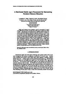
3.2 Engine Structure Figure 3 shows a different view of the structure of a workflow-based device. Its focus being on the engine, the figure depicts the applications as workflow instances. Workflow definitions and attributes are represented internally as workflow scripts. Scripts are stored in .wfs files, which when loaded into memory, are processed by the engine. We omit the other aspects of the scripts because they are unimportant for our discussion here.
.xpdl .wfs
Configuration Interface Engine SISARL-XPDL preprocessor Manager XPDL parser Workflow Workflow Workflow Instances Workflow Instances Instances instances
Workflow loader
Workflow variables, participants & attributes
General activity scheduler
Built-in activity accelerator
Workflow Processor Work queues Worker threads
Executables (.dll or .exe)
Time manager
Drivers and Event Handlers
Workflow Manager
Figure 3. Major embedded engine components The XPDL term participant in the upper right refers to a resource such as a hardware device (e.g., bar-code scanner, motor, sensor and even CPU), people, and so on. When assigned to do the work, participants carry out external activities. They are declared in workflow definitions along with participants that implement software activities, including computer programs, executables and interfaces, Resources exclusively owned and used by individual software activities are not thus declared, however. The engine has three major components: workflow manager, workflow processor and engine manager. The workflow manager processes the workflow scripts and has the workflow processor execute activities according to the scripts. We will return to describe these components in the next section. The engine manager manages the configurations of both the engine and application workflows
9
and is responsible for the initialization of the engine and loading workflow scripts of applications during initialization. It is also responsible for handling user requests and managing access to workflow-related definitions and optional contextual information. The diagram of the engine manager in Figure 3 is that of an engine used for development within EMWF. A developer can tune the engine via the configuration interface by changing its configuration parameters, which include the maximum number of threads and timer resolution. The engine manager has SISARL-XPDL preprocessor and XPDL parser locally, as shown in the figure, or can access the tools remotely. These tools make it possible for the developer to add new workflows defined in terms of SISARL-XPDL, translate them into standard XPDL, parsed XPDL definitions into workflow scripts and stores the scripts as .wfs files. We show these tools and .xpdl files of workflow definitions in dotted shapes to indicate the fact that a typical device, even one as complex as an intelligent medication cart, do not have these tools. By requiring XPDL definitions to be parsed off-line, the engine does not incur the substantial memory space and power required to run the tools. The current versions of EMWF engines allow workflow script files defining workflows to be added and removed. The engine must be restarted for the configuration changes to take effect. This means that all the workflows a device needs to operate in multiple modes or adapt while running must have already been in the system and initialized before the device starts to run. 4 WORKFLOW MANAGER AND PROCESSOR The workflow manager and workflow processor form the core of the engine. They contribute the bulk of memory footprint and context switch overheads of the engine. Needless to say that it is important to keep these overheads small. This objective is more challenging for embedded engines than engines used for enterprise computing. The execution times of general activities can be very small, especially for low-level embedded components. It follows that time spent to context switch between threads scheduling and executing general and built-in activities can be a large percentage of the overall run-time of such components. 4.1 Design Rationales An obvious way to minimize context switches is to have a single-threaded workflow processor execute all software activities: The thread alternatively invokes general activities and built-in activities as procedures and in-line functions. The workflow manager decides which activity of which workflow to execute based on the scheduling policy requested by the application. We
10
ruled out having single-threaded workflow processor by default. A reason is that embedded workflows can block on CPU, waiting for completion of external activities or user intervention, and any means to better utilize the CPU involves the use of additional threads. By making the maximum number of workflow-processing threads a configuration parameter of the engine, the developer can always choose the single-threaded configuration when it works for the device. There are two ways to structure a multi-threaded workflow processor: 1. All activities in each workflow are executed by thread(s) dedicated to the workflow. 2. Activities from multiple workflows are queued as work items and executed by worker threads serving the queues. To make good use of the respective thread models and APIs supported by the operating systems, the current version of the Linux EMWF engine, called LIWWE (Light-Weight Workflow Engine) in [37], uses the first strategy. The Windows CE engine uses the second. We will return to provide further details on the designs shortly. typedef struct activity_t { BuildinActivity; // TRUE for a built-in BuildinActivityType; * ActivityExe; // function name or .exe * Transitions; // array of transitions * ParticpantListHead; // Resources
…
} ACTIVITY; typedef struct workflow_t { * WorkflowScript; // Workflow definition
…
typedef struct worflow_instance_t { WORKFLOW* ThisWorkflow; WorkflowStatus; * StartTrigger; // start event or timer * EndTrigger; // end event or timer WfPriority; // base priority of wf ACTINSTANCE* RunningActivities;
…
* WfWideVariables; } WFINSTANCE;
} WORKFLOW; typedef struct package_t { * Workflows; // array of wf in pkg * Activities; // array of activities
Run-time data workflow instances
…
package instances
} PACKAGE; typedef struct activity_instance_t { ACTIVITY* ThisActivity; Autorun; // automatic or manual isRunning; PriorityIncrement;
wf-wide variables
…
activity instances
} ACTINSTANCE; typedef struct package_instance_t { PACKAGE ThisPackage; WFINSTANCE* RunningWorkflow; * PkgWideVariables; }
pkg-wide variables
Figure 4. Workflow and activity data structures
11
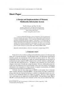
Figure 4 shows the structures of run-time data maintained by the engine on activity, workflow and package types and instances. (The XPDL term package means a container for grouping entities common in multiple workflow definitions to avoid duplicate definitions.) We omit data types in order to save space when there is no ambiguity. Most fields of structures in the figure are self-explanatory. Among the noteworthy ones is the AutoRun flag used to capture an execution control attribute of an activity. Its value being
TRUE
indicates that the engine is to start and finish the activity automatically. The opposite indicates manual mode; the execution of the activity requires explicit user interaction. In similar vein, StartTrigger and EndTrigger give the synchronization objects, if any, that signal to start the
workflow and end the workflow process. As examples, the starts of workflows in Figure 2 are triggered by timers firing periodically at the specified rates. The current versions of both EMWF engines trade off in favor of run-time overheads, sometimes at the expense of memory footprint. As stated earlier, the engine manager loads intermediate .wfs files of all workflows during initialization. This allows the workflow manager to dynamically allocate memory for all instances of activities and workflows during initialization. Many low-level embedded components (e.g., the workflows in Figure 2) have stringent timing requirements. For them, this is exactly what the system should do. Threads executing general activities and built-in activities of a workflow and a package of related workflows must be able to communicate. This is done by via workflow-wide and package-wide variables WfWideVariables and PkgWideVariables that are accessible by all threads working on the workflows. Each workflow instance has a priority, given by the value of WfPriority field in the workflow instance. This field captures the contextual information on
execution and resource allocation priority of the workflow provided by its definition. This is the default priority of all activities in the workflow: The definition optionally provides each activity with a priority relative to other activities in the workflow, and this information is captured by the field PriorityIncrement within the activity instance. 4.2 Activity Execution Again, in both EMWF engines, the workflow manager creates and initializes threads needed to execute software and built-in activities when the engine is initialized, a group of POSIX threads in the Linux engine and user-mode threads in the Windows CE version. All threads execute at fixed priorities.
12
4.2.1 Linux Version As stated earlier, workflows are executed by dedicated threads in the Linux engine LIWWE. The workflow manager attaches a thread to each workflow when it initializes the workflow and schedules the thread to execute both general and built-in activities in the workflow. The thread inherits the priority of the workflow. The workflow manager keeps track of the relationship between threads and workflows. When a thread executes an end activity, it is de-attached from the workflow and returned to the thread pool. On the other hand, when the EndTrigger of the workflow being executed signals to terminate the workflow process, the workflow manager may terminate the thread(s) attached to the workflow. A workflow may contain built-in split and merge activities. The former splits an activity into multiple successor activities, and latter merge multiple predecessor activities into a single successor. When a split occurs, the manager selectively attaches additional threads to execute the successors. When multiple threads join for a merge activity, the last thread that reaches the merge executes the merge operation. An obvious advantage of this design is that most of the transitions between activities incur no context switch. Another important advantage is that the workflow manager does not need to handle blocking built-in activities (e.g., delay and listen) specially. It can simply let the thread executing a workflow wait when it executes such a built-in. It is expensive for threads to change priority, however. For this reason, the current version of LIWWE does not support varying-priority within workflow: Priority increments of activities are ignored. 4.2.2 Windows CE Version The bottom half of Figure 3 shows the structures of workflow manager and workflow processor in the Window CE version of the EMWF engine. A configuration parameter is the number of priorities the engine supports. The workflow manager maintains a FIFO queue per priority. When a general software activity is ready to be executed, it is wrapped as a work item and placed in the queue at the priority of the activity (i.e., the sum of workflow priority and priority increment of the activity). The workflow manager has at least one worker thread dedicated to execute work items in each queue at the priority of the queue. In other words, ready activities are executed according to their priorities with ties among equal priority activities broken in FIFO order. Threads in the workflow manager and workflow processor interact in more or less the 13
leader/followers pattern [34], worker threads being followers. Let us focus first on the simple case where the workflows have no start, end and intermediate triggers [16], i.e., no blocking built-in activities. If the device were to have only such workflows, the workflow manager might have just one leader thread and let the leader execute at the highest priority. The leader process workflow scripts, queues ready general activities as work items, supervises their completion, executes built-in activities, which in turn leads to more activities be queued. Almost all built-in activities are simple. As depicted by the figure, they are not queued as work items. Rather the leader executes them itself; this allows functions for most built-in activities to be in-line. These functions of the leader are depicted as general activity scheduler and built-in activity accelerator in Figure 3. Specifically, worker threads signals the leader thread upon the completion of each general activity by setting a manual-reset completion event. When awaken by the event, the leader checks the completion status of pending (i.e., queued but yet to be completed) activities in priority order, starting from the one with the highest priority. For each completed activity it finds, the leader executes the successor built-in activity, queues the actuality or activities readied by the completion of the built-in activity. After it completes the work for that flow path, it continues to check the pending general activities and serves them until it find no more completed activities waiting for its attention. It then resets the completion event and return to wait. Clearly, the simple pattern with a single leader does not work because many generic built-ins (e.g., delay, listen) are blocking. A simple way is to have the leader dispatch a new leader just before it goes to wait. This scheme can work for a simple device, but can use more threads than necessary for complex SRARD devices like intelligent medication carts. The current workflow manager takes advantage of the fact that workflows are known before the engine starts and that a thread can wait simultaneously for multiple objects to reduce the number of threads needed to help the leader wait for them. For example, the time manager shown in Figure 3 is a helper thread that assists the leader by setting and waiting for all timers used for all running workflows. The engine also uses at least one helper thread to monitor events, rules, result tokens, etc. that standard XPDL allows to be triggers for which workflows may wait at the start and end, as well as within them. An advantage of this engine is that it can easily support varying priority within workflows. Every transition from one general activity to another incurs at least one context switch. This is one of the major disadvantages when compared with the Linux engine.
14
5 SISARL-XPDL The WfMC standard XPDL [16] has been widely used for not only business applications but also many industrial applications (e.g., factory and warehouse management) with embedded components. There is no question that we can use the full XPDL for defining workflows in SRARD and similar devices. A design decision of SISARL-XPDL, the embedded workflow definition language supported by EMWF, involves the selection of XPDL elements to be parsed into workflow scripts for execution by EMWF engines. It makes sense to start with a minimal SISARL-XPDL. We can add more elements into it as needed in the future without having to be concerned with backward compatibility. By excluding XPDL elements not essential for SRARD, we aim at keeping the EMWF XPDL parser simple and resultant workflow scripts generated by parser small. 5.1 Subset of XPDL Elements Table 2 lists examples of standard XPDL elements included in SISARL-XPDL. The table divides the elements for definitions of workflows and their related attributes into three parts: workflow data, workflow structure, and workflow control. How some elements listed here are to be used can be readily deduced from their names. We have talked about some of the elements in passing in earlier sections. Table 2. Examples of XPDL elements in SISARL-XPDL
Class A
Workflow Data
TypeDeclaration, DataType, BasicType, SchemaType, DeclaredType, RecordType DataField, InitialValue
Workflow Structure
Package, Pool, Lane, WorkflowProcess, Activity, BlockActivity, SubFlow, Task, Application, Implementation
Workflow Control
Transitions,TransitionRef,TransitionRestriction, Route, Join, Split, StartEvent, EndEvent, Condition, IntermediateEventTrigger, Deadline, Priority
Class B
Resources
ParticpantType, Participant, Application FormalParameter, ActualParameter,
Class C
Extensions
Period, ExtendedAttributes
We use Figure 5 to help us explain some more. The figure depicts a simplified diagram of a system consisting of a smart medication dispenser and its user. The diagram is in a style similar to the ones used by some workflow graph editors. The outermost rectangle represents a package, i.e., a container for holding common entities. The package here contains two workflow processes:
15
Each process has one or more workflows. Here, the dispenser process has three interacting workflows; they are notify_workflow, timer_workflow, and schedule_workflow. The bottom rectangle encircles the manual workflow process of user activities. Associated with each workflow definition is the declaration of participants needed by the workflow. Examples here are user and sched ( ) needed by the manual and schedule workflows, and alarm and clock needed by the notify workflow. A sub-flow is a workflow called synchronously by another workflow, e.g., schedule_workflow is a sub-flow of notify_workflow. A workflow may also be called asynchronously, as exemplified by
Dispense dose(s) & set timer Sched ( ) alarm, clock …
WorkflowProcess dispenser
how notify and timer workflows here interact.
Notify user by alarm notify_workflow Update record
trg_2
notify_workflow timer_workflow timer_workflow
R trg_1
late
schedule_ workflow
Send email Compute next dose time & medication(s)
schedule_workflow Follow direction
Report arrival
Figure 5. Workflows in medication dispenser The example has only a two-way XOR split (i.e., an if-else built-in activity) depicted as a circle labeled R in notify_workflow graph. In general, the
Route
activity can have arbitrary numbers of
incoming and outgoing transitions. When used with transition restriction, Route can implement arbitrary complex flow logic, including combination of conditional XOR and AND split of outgoing transitions and join of incoming transitions. XPDL Event activity is a general primitive for alternating the courses and timing of a workflow process. An event trigger can be time, timer, rule, results, result errors, and so on. The manual process illustrates the use of StartEvent. In this case, it is an alarm event (trg_2). When sounded, it triggers the start of the manual workflow: The user reports to the dispenser, which in turn sets the intermediate event (trg_1) used by notify_workflow. 16
Finally, XPDL schema provides a standard way for introducing user specific extensions. We have not yet fully exploited this aspect to add workflow attributes, such as rate and latency, which when declared can be used to help the engine better service workflows with rate and deadline constraints. 5.2 Built-ins for Behavior Coordination Another design decision of SISARL-XPDL involves the choices of mechanisms for behavior coordination to be included as special-purpose built-in activities supported by EMWF: The special-purpose built-in activities provided by the current version of SISARL-XPDL are listed in the left half of Table 1. EMWF makes these commonly used building blocks of behavior-based robotic devices available and easily reusable. To justify their inclusion, we digress momentarily to observe ways in which a workflow-based design and implementation may map basic operations of a behavior-based robotic device to activities and workflows. Basic operations can be divided into reactions and behaviors (or reactive behaviors versus deliberative behaviors according to the definition in ESAIR [32]). A reaction is a simple basic operation (e.g., stop, spin) during which the system keeps no state. Even a simple robotic device (e.g., an automatic vacuum cleaner) can have a large number of reactions. A behavior is a sequenced set of reactions. The reactions in the set execute one or few at a time and thus perform a more complex operation together. This way of combining reactions into behaviors is called sequencing. It is the way advocated by authors of [35] and used in ESAIR. In a small grain workflow-based design and implementation, each reaction is an activity. A behavior is a compound activity or a workflow. It is then defined by a workflow graph in which nodes are reactions and edges (transitions) are sequencing of reactions. It is common to manage transitions between reactions according to a finite state machine, executed from start to finish with or without external intervention. Alternatively, in a large grain workflow-based design, activities are behaviors. In other words, each behavior, once starts, runs to completion without requiring engine attention. EMWF currently supports this option. In this case, some transitions between activities are coordination of behaviors. As shown in Figure 6, there are two major types of behavior coordination mechanisms: arbitration and command fusion [35]. At each selection time, an arbitration mechanism selects
17
one behavior from a group of behaviors competing for the control of the robot. A command fusion mechanism selects multiple behaviors and let them contribute to the control of the robot. Behavior coordination mechanisms Arbitration Prioritybased
Statebased
Command Fusion Winnertake-all
Voting Superposition
Multiple objectives
Fuzzy
Figure 6. Taxonomy of behavior coordination mechanisms Arbitration mechanisms are further divided into priority-based, state-based and winner-take-all. Fixed priority, variable priority and subsumption mechanisms are priority-based, with the fixed-priority mechanism being the simplest of all mechanisms. When multiple behaviors send commands to the arbiter, the arbiter sends only the command of the highest priority behavior. In essence, subsumption is a generalization of fixed priority arbitration. Its disadvantages include that behaviors cannot cooperate and control structure is hardwired, and its advantages over fixed-priority arbitration are not sufficient to warrant its added complexity and variability [36, 37]. For similar reasons, variable priority is also not widely used. This is the reason that EMWF supports only fixed priority arbitration for now. There are four major categories of command fusion mechanisms: voting, superposition, multiple objective behavior coordination and fuzzy command fusion. We chose to support voting and superposition.
Like fixed priority arbiter, voter and superposition mechanism can be
implemented using route activity. We mentioned earlier that behaviors sometimes need to send and received data. Push and pull data built-in activities allow them to do so asynchronously. The mode change activity enables the device to reconfigure while running to a limited extent. The limitation arises from that the current version of EMWF requires all workflow scripts be loaded at initialization. We will work to remove this limitation in a future version. 6 CASE STUDIES We are evaluating the workflow-based design for SRARD, and for smart personal and home automation devices in general, along multiple dimensions to seek answers to many questions, including the ones listed below:
18
1
Are the higher memory and runtime overheads of workflow-based devices within acceptable ranges?
2 Is the workflow approach indeed effective in reducing the time and effort needed for design and building of component-based SRARD and configure and customize the devices after they are built? 3 Can the paradigm enable developers with minimal expertise in robotics build robotic devices from reusable components with quality comparable to handcrafted ones? 4 What other uses are there of workflow definitions, engines, management environments and tools? The case studies summarized here hardly scratch the surface of the experimentation and evaluation work required to answer these questions. What we found from our initial experiments are encouraging enough for us to move forward and do more. 6.1 Memory and Run-Time Overheads The purpose of the first experiment carried out on LIWWE as soon as the preliminary version of the engine became available was to assess the overheads introduced by the engine and application workflows. EMWF and the workflow approach supported by it are not the way to go when optimizing run-time performance, size and power consumption is the primary design goal. Most SRARD and similar devices are not demanding in these aspects: Still, it is important to be sure that overheads one must endure for flexibility is acceptable. In this experiment, we measured the resident memory sizes and total CPU times of two small workflow-based applications: One includes processes with route activity between general activities. In other words, it has splits and joins in its control path. The processes in the other applications contain only general activities and straight line transitions. Both applications have no blocking built-in activities. We used top command to measure the total resident memory size of application workflows and the engine and time command to measure their total CPU time. We then implemented the applications with customized programs and measured their residence memory sizes and total CPU times. Table 3 summarizes the results from the measurements. One can see that the workflow-based applications and the engine consume up to 50% more memory space than customized codes. The executable code of the engine itself is only 64 KB. However, the engine must maintain data structures of loaded packages and workflows and they take up much more space than the engine.
19
Table 3. Comparison of memory sizes and execution times Maximum resident memory size in megabits Workflows & engine Customized code Application without route
38
25
Application with route
39
26
Average CPU time in seconds Workflows & engine Customized code Application without route
5.7796
5.5174
Application with route
6.4020
6.3474
On the other hand, we can also see from the table that the total run time overhead of the workflow application and the engine is only slightly larger than that of the customized code for both applications. This is what we expect. As stated earlier, LIWWE uses dedicated threads to execute workflows and hence does not introduce context switches between general and built-in activities. We will repeat this measurement as soon as the Windows CE engine is stable enough for this experiment. Because the bulk of the memory space is taken up by application data structures and they are independent of the engine, we expect that memory space overheads are comparable for both engines. However, the run-time overhead of workflow applications on Windows CE engine may be higher because the engine uses different threads to execute general and built-in activities. 6.2 Usage and Effectiveness Our experimentations on application of workflow-based design and implementation paradigm to smart automation and robotic devices are too limited to give definitive answers to the remaining questions posted above. However, from what we have done so far, we are convinced that componentization comes naturally with workflow-based design of such embedded devices, as advocates of workflows say about enterprise applications. Indeed, the workflow engine provides a flexible platform for integrating reusable components. One can easily build devices with different functionalities from components by modifying the graphs defining their workflow processes and/or using different participants for activities. To illustrate, Figure 7 shows the graph of workflows in an automatic vacuum cleaner. The figure is almost the same as in Figure 2, except that the workflow graphs in them are different. Indeed, many of the software activities in them are essentially the same. (Of course, the robot components used for intelligent medication 20
cart and vacuum cleaner differ significantly.) If we want to build a toy sumo, we can do so simply by replacing the back and random move maneuver by a move back and hit maneuver.
Sense Sense edge edge
Edge Edge 20Hz
Contact Contact 10Hz
On edge?
No Yes
Edge maneuver maneuver Edge
Sense Sense contact contact Contacted? Yes
Track Track
2Hz
No
Find Find obstacle obstacle Obstacle found?
(Contact (Contact maneuver) maneuver)
No
Track maneuver maneuver Track
Yes
Wait Wait for for the the move move Environment Interaction
Back & & random random Back move move
Workflows
Move Move the the robot robot Robot Components
Figure 7. Workflows in a automatic vacuum cleaner We are also using workflows for the specification of the operations of the devices, especially semi-automatic devices that rely on their users to perform critical operations. Specifically, according to the SISARL component model [38], a device is specified by an operational (behavior) view specification, in addition to a traditional, structural view specification on how the device is to be built. The operational view specification of a device is written in terms of workflow graphs. The graphs define the actions of the user(s) and collaborations between the user and the device in the same way as they define the work by the device. Returning to Figure 5, we note that the definitions of timer, notify, and schedule workflows are parts that define the implementation of the medication dispenser. Together with the definition of the user workflow process, they provide a rigorous specification of how a smart medication dispenser works, how its user may act and how the device and its user interact. In many ways, the workflow-based specifications are more intuitive and easily understandable than the more commonly used state machine specifications. Other advantages of workflow-based specification are that specifications are executable and map directly to implementation. In a parallel effort, we are developing a simulation environment that will enable us to experiment with and evaluate new device designs and prototypes as soon as they are specified and during
21
their development. In particular, by executing the operational specification of a new device with user activities based on validated user models, the environment can help us to better assess the usability of the device throughout its development process. 7 SUMMARY We have described in earlier sections the design and implementation of EMWF. The embedded workflow framework provides light-weight engines for Linux and Windows CE platforms. It also provides a small but extensible language, called SISARL-XPDL for defining embedded workflow processes. The SISARL-XPDL preprocessor translates special-purpose built-in activities into standard XPDL. Unlike some existing engines, the EMWF engines cannot execute XPDL directly. Commonly used execution languages such as BPEL are unsuitable for our purpose. For these reasons, EMWF also has a XPDL parser that translates workflow process definitions into workflow scripts for the engine. Both engines, SISARL-XPDL preprocessor and EMWF XPDL parser will be released under GPL license later this year. We chose to build the current version of the above mentioned simulation environment on Windows Workflow Foundation because we want a prototype environment for experimentation in minimal time. We will port part of the environment to EMWF in the near future. The work on case studies reported here is only the tip of the iceberg of all the work to be done to demonstrate that workflow paradigm is indeed an excellent way to build smart and robotic devices for personal and home use and for automation in care providing institutions. We do not yet have working workflow-based device prototypes from which we can systematically extract benchmarks for performance measurement. We will repeat the experiment described above to better quantify overhead penalties of workflow-based designs as benchmarks become available. 8 ACKNOWLEDGMENT This work is partially supported by the Taiwan Academia Sinica thematic project SISARL, Sensor Information Systems for Active Retirees and Assisted Living. 8 REFERENCES [1] iRobot Home Robots, http://www.irobot.com/
22
[2] Forizzi, J. and C. DiSalvo, “Service robots in domestic environment: a study of Roomba vacuum in the home,” Proceedings of ACM/IEEE International Conference on HRI, March 2006. [3] Kulyukin, V. A. and C. Gharpure, “Ergonomics-for-one in a robot shopping cart for the blind,” Proceedings of ACM/IEEE International Conference on HRI, March 2006 [4] Kaneshige,Y., M. Nihei, and M. G. Fujie, “Development of new mobility assistive robot for elderly people with body functional control,” Proceedings of IEEE/RAS-EMBS,, February 2006. [5] Lin, C. H., Y. Q. Wang and K. T. Song, “Personal assistant robot,” Proceedings of IEEE International Conference on Mechatronics, July 2005. [6] Mataric, M. J., J. Eriksson, D. J. Feil-Seifer, C. J. Winstein, “Socially Assistive Robotics for Post-Stroke Rehabilitation,” Journal of Neuroengineering and Rehabilitation, Vol. 4, No. 5, 2007 [7] Gockley R., and M. J. Mataric, “Encouraging physical therapy compliance with hand-off mobile robot,” Proceedings of ACM/IEEE International Conference on HRI, March 2006. [8] Thrun, S., “Toward a framework for human-robot interaction,” Human-Computer Interaction, Vol. 19, 2004. [9] Fong, T., I. Nourbakhsh, and K. Dautenhahn, “A survey of socially interactive robots,” Robotics and Autonomous Systems, Vol. 42, 2003. [10] “Speci-Minder autonomous hospital robots,” http://robots.net/article/2156.html, 2007 [11] http://www.informatics.nhs.uk/cgi-bin/item.cgi?id=1155, “Washington hospital implements drug dispensing robots,” February 2005. [12] Grudin, J., “Three faces of human-computer interaction,” IEEE Annals of the History of Computing, Vol. 27, No. 4, 2005. [13] Coradeschi, S. and A. Saffiotti, “Symbiotic robotic systems: humans, robots and smart environments,” IEEE Intelligent Systems, 2006. [14] SISARL (Sensor Information Systems for Active Retirees and Assisted Living), http://sisarl.org [15] Workflow definition, http://en.wikipedia.org/wiki/Workflow [16] XPDL (XML Process Definition Language) Document, http://www.wfmc.org/standards/docs/TC-1025_xpdl.2.2005-10-03.pdf, October 2005 [17] YAWL (Yet Another Workflow Language), http://yawlfoundation.org/
23
[18] BPEL (Business Process Execution Language), http://en.wikipedia.org/wiki/BPEL [19] Open Source Java XPDL editor, http://www.enhydra.org/workflow/jawe/index.html [20] Windows Workflow Foundation, http://msdn2.microsoft.com/en-us/netframework/aa663328.aspx. [21] WfMC: Workflow Management Coalition, http://www.wfmc.org/ and WfMOpen, http://wfmopen.sourceforge.net/. [22] Enhydra Shark, http://forge.objectweb.org/projects/shark [23] Microsoft Robotic Studio Developers Center, “Introduction to Microsoft Robotic Studio,” http://msdn2.microsoft.com/en-us/library/bb483024.aspx. [24] Baum, D., M. Gasperi, R. Hempel and L. Villa, Extreme MINDSTORMS, APRESS™ publication, 2000. [25] Montemerlo, M., N. Roy and S. Thrun, “Perspectives on standardization in mobile robot programming: the CARMEN toolkit,” Proceedings of IEEE/RSJ International Conference on Intelligent Robots and Systems, Vol. 3, 2003. [26] Nesnas, I. A. D. et al., “CLARAty and challenges in developing interoperable robotic software,” Proceedings of IEEE/RSJ International Conference on Intelligent Robots and Systems, vol. 3, 2003. [27] Cote, C., et al., “Robotic software integration using MARIE,” International Journal of Advanced Robotic Systems, vol. 3, 2006. [28] Utz, H., S. Sablatnog, S. Enderle, and G. Kraetzschmar, “MIRO – middleware for mobile robot applications,” IEEE Transactions on Robotics and Automation, vol. 18, 2002. Makarenko, A., A. Brooks, and T. Kaupp, “ORCA: components for robotics,” Proceedings of IEEE/RSJ International Conference on Intelligent Robots and Systems, Workshop on Robotic Standardization, 2006. [30] Bruyninckx, H., “Open robot control software: the OROCOS project,” Proceedings of IEEE/RSJ International Conference on Intelligent Robots and Systems, 2001. [31] Vaughan, R. T., B. P. Gerkey and A. Howard, “On device abstractions for portable reusable robot code,” Proceedings of IEEE/RSJ International Conference on Intelligent Robots and Systems, vol. 3, 2003. [32] Huang,Y. L., E. C. Hsia, and J. S. Hu, “The design and implementation of an embedded software architecture for intelligent robots,” submitted to 2007 IEEE/RSJ International Conference on Intelligent Robots, 2007
24
[33] Chang, S.Y., Y. F. Lu, T. W. Kuo, and J. W. S. Liu, “The design of a light-weight workflow engine for embedded systems," Presented at Workshop on Software and Systems for Medical Devices and Services, December 2007. [34] Schmidt, D. C. et al., “Leader/followers: a design pattern for efficient multithreaded event de-multiplexing and dispatching,” http://ftp.icm.edu.pl/packages/ace/ACE/PDF/lf-PLOPD.pdf [35] Lenser, S. and M. Veloso, “Behavior overview,” October 2003. http://www.cs.cmu.edu/~robosoccer/cmrobobits/lectures/behavior-overview.pdf [36] P. Pirjanian, “Behavior coordination mechanisms – state-of-the-art,” Institute for Robotics and Intelligent Systems Technical Report IRIS-99-375, 1999. [37] J. Jones and D. Roth, Robot programming: a practical guide to behavior-based robotics, McGraw-Hill/TAB Electronics, 2003. [38] T.Y. Chen, P. H. Tsai, T. S. Chou, C. S. Shih, T. W. Kuo, and J. W. S. Liu, “Component Model and Architecture of Smart Devices for the Elderly,” Proceedings of the 7th Working IEEE/IFIP Conference on Software Architecture, pp. 51 – 60, February 2008.
25