VoIP Packet Aggregation based on Link Quality Metric for Multihop Wireless Mesh Networks Andreas Kassler, Marcel Castro, Peter Dely Computer Science Department Karlstad University, Karlstad, Sweden {andrkass, marccava}@kau.se,
[email protected]
Abstract - Providing Voice over IP in WLAN based wireless meshed networks is an important service for the future wireless internet. However, the transmission of small (voice) packets imposes high overhead which leads to low capacity for VoIP over 802.11 based multihop meshed networks. By combining several small packets into larger aggregated ones, it is expected that overhead can be significantly reduced thus incapacity for VoIP services. When mesh relay nodes aggregate small packets, there is an inherent trade-off regarding packet size. Aggregating more packets leads to larger packets, reduces the overall number of packets in the mesh and thus reduces multi-hop contention and packet loss due to collisions. However, such larger aggregated packets can lead to higher packet loss for a link that operates at low signal quality. For such links, aggregating fewer packets can be beneficial. Classical aggregation strategies typically operate end-to-end without considering those aspects and are therefore suboptimal. In this paper, we propose a new adaptive hop-by-hop aggregation scheme that calculates target aggregation sizes per each hop based on wireless link characteristics. Simulation results show that our approach is very effective, outperforms static aggregation schemes in various performance parameters and increases capacity for VoIP in meshed networks significantly.
I. INTRODUCTION Voice over IP (VoIP) over Wireless is gaining momentum due to the popularity of applications such as Skype and higher WLAN availability. Increasing the popularity of such wireless VoIP requires, among other things, ubiquitous WLAN coverage. To this extent, 802.11s based multihop WLAN meshed networks (WMNs) are a viable and inexpensive solution. In WMNs, wireless access points communicate with each other wirelessly forming a true wireless, mesh based access network of mesh relay nodes (MRN). Mesh gateways (MG) provide internet connectivity and standard mobile clients attach to MRNs, which forward packets via other MRNs to other meshed clients or through MGs to the internet. Therefore, the wireless backbone comprised of MRNs and MGs is similar to static, internet connected Ad Hoc networks. WLAN meshes are likely to be part of 4G networks and several projects such as the EU-funded IST-DAIDALOS (www.ist-daidalos.org) are currently investigating how to seamlessly integrate such heterogeneous network technologies. A major problem is scalability of WMNs. Currently, 802.11s WMNs are based on 802.11 basic MAC layer access method DCF, and they suffer from the same intraand interflow interference of multihop forwarding as in standard MANET. While multi-radio, multi-channel solutions could minimize that problem, MAC and PHY
layer overhead for the transmission of small packets such as packetized voice samples is still high. For example, when G.729a voice codec is used, voice payload is 20 bytes but additional 40 bytes are required for RTP/UDP/IP headers per packet, every 20 ms. In addition, MAC layer needs to spend significant time in contention phase (in average around 310μs) depending on competing traffic and additionally contributes to the overhead using SIFS, DIFS and ACK. Including PHY overhead, sending a 20 byte voice packet (15 μs) requires thus around 800 μs at 11 mbps [1]. The large number of small packets common with VoIP services is the primary reason for contention and congestion in multi-hop WMN as all intermediate relay nodes have to process and forward a significant number of small packets. Therefore, an important suggestion is to keep the transmission overhead per packet small. There are several mechanisms how overhead can be reduced. For example, header compression schemes such as robust header compression (ROHC) [2] can bring down the overhead of 40 byte RTP/UDP/IP headers to 2 byte connection ID when a single flow and one hop is used. However, payload size is still small compared to MAC and PHY overhead and WMNs are inherently multi-hop in nature. Therefore, other mechanisms to reduce overhead are strongly desired. Capacity of WMNs can be increased significantly by aggregating (combining) several smaller packets into larger ones. The overall number of packets is thus reduced, average packet size increased and contention will take place only once for the larger packets. A relay node will then process fewer large packets instead of many small ones. While such aggregation mechanisms have been proposed for single-hop infrastructure WLAN, designing an aggregation strategy for multihop WMNs is a hard problem. In infrastructure WLAN, the sender has complete knowledge about link characteristics of one hop neighbors and can thus calculate an optimal packet size for aggregation [3]. In a multihop environment, signal quality and congestion for each link is different. When mesh relay nodes aggregate small packets, there is an inherent trade-off regarding packet size. Aggregating more packets leads to larger packets, reduces the overall number of packets in the mesh and thus reduces multi-hop contention and packet loss due to collisions. However, such larger aggregated packets can lead to higher packet loss for a link that operates at low signal quality. For such links, aggregating fewer packets can be beneficial. Packet aggregation can be classified as end-to-end or
II. PREDICTING PACKET SIZE FOR AGGREGATION THROUGH LINK QUALITY This section presents the strategies adopted to find the optimum packet size based on current link characteristics (sub-section A). It also presents a detailed description of the proposed adaptive algorithm (sub-section B). A. Determining packet size End-to-end delay, jitter and packet loss ratio are the most important QoS parameters determining VoIP quality. To achieve a good voice quality all three parameters need to stay below certain thresholds. For example, using G.729a voice codec requires smaller than 150 ms end-to-end delay and less than 2% packet loss in order to provide acceptable quality [7]. Due to the retransmission scheme of the IEEE 802.11 MAC layer, a reduction of packet loss ratio has also beneficial effects on jitter and delay. Therefore, any aggregation scheme should aim to increase the number of VoIP calls which can be supported at an acceptable quality
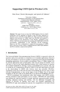
by reducing the overall packet loss ratio while keeping end-to-end delay low. The reasons for packet loss in WMNs are manifold. If the signal-to-noise ratio (SNR) is too low, the receiver cannot decode a frame correctly and drops it. If a node tries to send or forward packets at a higher rate than the MAC layer can service, the packet queue of the node fills up and eventually packets in the queue have to be dropped. As a consequence of the hidden-terminal problem, two nodes in the vicinity can start to transmit at the same time, resulting in collisions and packet loss. Finally, in multi-hop networks a node might not have a valid route to a destination so packets are queued until a route becomes available. If this takes too long, the queue might overflow. Packet size is an important factor for controlling the network load and the packet loss ratio. As stated in section I, due to the MAC layer overhead, small packets have poor efficiency and increase multihop contention. Large packets have better efficiency, but are more likely to be dropped due to frame errors (FER) than small packets for a given biterror rate. In theory, there is a relationship between the SNR and the bit-error rate (BER). Depending on the coding scheme and the card sensitivity, a bit error probability can be found for a given SNR value [13]. Furthermore, for a given BER the frame error rate can be approximated as 1-(1-BER)n, where n is the frame length in bits. Consequently, the SNR can be used to predict the loss probabilities of frames with different lengths. Although some papers [8],[9] argue that it is hard to obtain such mapping, [10][11][12] show that the SNR has the potential to significantly improve wireless link quality prediction and hence packet loss estimation. Therefore our scheme uses the SNR for determining the optimum frame size used for aggregated packets. 80 m
100
70 m
60 m
50 m 128 bytes packet size 328 bytes packet size 528 bytes packet size 728 bytes packet size 928 bytes packet size 1028 bytes packet size 1128 bytes packet size 1328 bytes packet size 1528 bytes packet size
80
Packet Loss Ratio (%)
hop-by-hop. In end-to-end aggregation, all packets towards a common destination are aggregated at the ingress node only. In hop-by-hop aggregation (de-)aggregation is done at every node, which leads to higher complexity and potentially higher delay but yields better aggregation possibilities. In a realistic WMN deployment, link characteristic and load will be different for each hop. Therefore, a hop-by-hop aggregation scheme will allow to optimize the packet size used for aggregation for each hop separately. This allows then to trade-off packet loss due to contention and bit errors potentially outperforming end-to-end aggregation strategies. However, current approaches on packet aggregation such as [1], [4], [5], [6] do not consider the influence of link quality on packet size or consider only end-to-end path quality [6] due to the use of routing metrics such as WCETT. Here, packet size for aggregated packets is calculated based on the route quality because a “good” route can potentially carry larger aggregated packets. The problem with such approach is that metrics such as WCETT reflect path characteristics and are suitable for end-to-end aggregation and thus achieve suboptimal performance. If there is a bottleneck link such as one characterized through low signal quality, this will lead to a small packet size for end-to-end aggregation and the benefit of aggregating will be small. The key idea of our paper is to use hop-by-hop aggregation and for each hop derive an optimal packet size for the aggregated packets. Therefore, the overall aggregation along a path will not be constrained by the weakest link leading thus to significant performance improvement, as our evaluation section will demonstrate. The rest of this paper is structured as follows: In Section II we will derive a mapping to an optimal packet size for aggregation based on link characteristics. Based on this packet size estimation, an adaptive aggregation algorithm was developed. Section III presents experimental results gained through simulations that demonstrate the significant capacity increase of our adaptive scheme. Finally, we draw conclusions of this work in Section IV.
60
40
20
0 4
6
8
10
12
14
Signal-to-noise Ratio (dB)
Figure 1: Packet loss rate as function of SNR and packet size
To obtain the mapping between SNR, packet size and packet loss ratio, a series of simulations using ns-2 with the shadowing model and the channel model proposed by [13] was conducted. UDP packets were sent between two static wireless nodes at a rate of 64 Kbit/s. The packet size and node distance were gradually increased from 128 to 1528 bytes and from 10 to 105 m. For each packet size and node distance the average SNR and the packet loss ratio was
calculated. SNRs values have been calculated using unicast packets with standard 802.11 link layer retransmission enabled. SNR values of erroneous packets have also been taken into consideration, different from [8] which measures SNR using fixed broadcast packet size (1500bytes) and accounts only for successfully received packets1. Figure 1 shows packet loss ratio curves for different packet sizes and channel qualities. Above 11 dB SNR there is no packet loss due to FER. Between 11 and 5 dB a sharp increasing packet loss ratio can be observed. Here, for a given SNR, smaller packets cause less packet loss than larger packets. For example, with an SNR of 8.5 dB 128 byte packets virtually cause no packet loss, while the packet loss ratio for 1528 byte packets is about 48%. The curves in Figure 1 are specific for the network topology and settings described in Section III. 1600
Simulation Result PL < 0.2% Curve fitting 0.2% with 0.0035e^(1.2255*x) Simulation Result PL < 0.5% Curve fitting 0.5% with 0.0053e^(1.2066*x) Simulation Result PL < 1% Curve fitting 1% with 0.0059e^(1.2196*x)
1400
Packet Size (bytes)
1200
1000
800
600
400
200
0 8
8.5
9
9.5
10
10.5
11
Signal-to-noise Ratio (dB)
Figure 2: Maximum packet size for different loss ratio probabilities
The values in Figure 1 were used to find the optimum packet size, which yields 0.2, 0.5 and 1% packet loss ratio due to frame errors for different channel qualities per link. For each packet size p, the point [x/0.2%] was determined. The obtained x-values and the corresponding packet sizes p are plotted in Figure 2. These values can be approximated with the exponential functions, which were found through curve fitting. For example, the packet size SIZEmax which yields 0.2% packet loss due to frame errors can be calculated according to equation 1.
SIZEmax = 0,0035 * e1, 2255*SNR
(1)
Different services tolerate different packet loss rates. Therefore, application requirements and network topology determine the curve fitting which yields the packet loss suitable for a given application. For example, if application is less sensitive to packet loss, the curve with target packet loss 1% could be used. B. Adaptive Packet Aggregation Our packet aggregation scheme consists of two 1
Reporting measured SNR for both corrupted and successfully received packets should improve the usefulness of such measurements for link assessment as a broader sampling space is used.
components – a protocol for determining and exchanging the optimum packet size on a link and a packet aggregation algorithm. The SNR of a link is a function of signal strength and noise, which are not necessarily the same at the sender and the receiver of a given packet. Therefore, the receiver has to propose a given packet size SIZEmax based on the SNR and the target acceptable loss ratio and inform the sender about it. We propose that the receiver constantly measures the SNR of all received packets and stores a moving average of the SNR for each link or neighbor. Using the equation 1, it is possible to calculate the packet size which yields e.g. 0.2% packet loss ratio. If all nodes apply the same policy, less then 1% packet loss due to FER is caused on a five hop route. The receiver of a given packet then periodically informs its neighbours about that packet size SIZEmax. In our implementation, the packet size information is piggy-packed on AODV-HELLO messages, which are sent to keep routes alive. When a node receives an AODV-HELLO message, it reads the packet sizes for its neighbouring links and stores it in its routing table. Although our implementation utilizes AODV protocol messages to promote packet size information, other options are possible. For example the packet size information can be promoted by modified MAC ACK frames, neighbour discovery protocol messages, or special probe packets. The second part of our aggregation scheme is a hop-by-hop aggregation algorithm for IP packets, which is based on the end-to-end aggregation algorithm proposed in [14]. The aim of the algorithm is not to add extra delay or overhead unless necessary while providing a good aggregation ratio and to adapt the packet size to the link quality. These properties are controlled by four parameters - SIZEmin, which represents the minimum size of an aggregation packet, SIZEmax, which specifies the maximum packet size obtained as described before, SIZEfactor for controlling the trade-off between loss due to FER and contention and MAXdelay which denotes the maximum forced delay expected. The algorithm works as follows: at every hop, received packets are marked with a timestamp and stored in a queue located between the routing module and the MAC layer. As soon as the MAC layer becomes idle, the aggregation algorithm tries to create an aggregation packet which is passed down to the MAC layer. All packets in the queue with the same next hop can potentially be aggregated (up to a maximum size of SIZEmax*SIZEfactor). If the cumulative size of those potential packets with same next hop is greater than SIZEmin the packets are aggregated and passed to the MAC layer. If the size is below SIZEmin, only packets which are older than MAXdelay are aggregated. If none is older, the queue stays idle and nothing is sent. If exactly one packet is older, the queue sends the packet as it is, without adding an additional header. If at least two are older, they are aggregated and passed to the MAC layer. Packets are aggregated by adding a new IP-header in front of the concatenated packets. The additional IP-header causes an overhead of 20 bytes per aggregation packet. Using a specific value in the protocol field of the IP-header,
We implemented the adaptive hop-by-hop aggregation in ns-2 simulator version 2.26. For comparison we also implemented a static hop-by-hop aggregation, which is explained later in this section. The 802.11 physical layer in ns-2.26 is overly simplified. Nodes receive packets only when the signal from the sender is greater that the receive threshold. However, the impact of wireless transmission error due to bad channel quality is completely ignored, meaning that BER is not considered in order to determine whether one frame is transmitted correctly. We replace this part of 802.11 function with code developed in [13], so that SNR is used to determine BER and FER by the empirical curves measured for Intersil HFA3861B card [15], and determine whether the frame is received correctly. We use shadowing radio propagation model with path loss exponent of 2.5 and shadowing deviation of 1.1dB, and the receiving and carrier sense threshold of 83.50dB and 90.81dB, respectively. We use 1Mbps basic rate and 11Mbps channel rate based on IEEE 802.11b without RTS/CTS. Each simulation runs for 120 second. The topology is depicted in Figure 3, which is comprised of wireless and wired nodes. Node 0 represents a server, e.g. a PSTN-gateway, connected with a Fast-Ethernet link (100 Mbit/s) to the router Node 1, which itself has a wired Ethernet connection to Node 2. Node 2 is a Mesh Gateway interconnecting the wired and wireless network. Node 3 is a Mesh Relay Node, which only forwards traffic inside the mesh network. Node 4 and 5
m 55
III. PERFORMANCE EVALUATION
are Mesh Relay Node where clients are connected. We used AODV-UU [16] as the base routing protocol to provide internet connectivity for mesh relay nodes. AODV-UU is used in half-tunneling mode, which adds an encapsulation header for all packets towards the internet. However, our packet aggregation mechanism can be deployed with any routing protocol more suitable to a multi-channel, multi-radio mesh scenario. We compare our adaptive algorithm with a static aggregation algorithm that does not take link quality information into account for packet aggregation. It is also known as forced delay aggregation [5]. Here, each incoming packet is given an explicit timestamp; when that packet has been delayed for a period longer than a statically configured maximum aggregation delay (MAXdelay), it is marked as available for transmission. When sufficient packets arrive with the same next routing step such that their combined size meets the MTU of the outgoing link, they are combined into an encapsulation packet and placed in an explicit transmission queue. The size of each internal queue can not exceed that of the MTU for the outgoing link; any available packet are aggregated and marked for transmission when an incoming packet would increase the sum of the packet sizes to be larger than MTU. In our experiments, maximum aggregation delay was fixed to 5ms for both aggregation methods. In the static aggregation, the MTU of 1500 bytes was used. A SIZEmin of 101bytes and SIZEfactor of 2 was used in the adaptive aggregation.. = d0
a node can distinguish between aggregation and non-aggregation packets. SIZEmax only considers loss due to FER and the calculations imply that all packets are exactly of size SIZEmax. In fact, the aggregation algorithm cannot always produce such large packets, because the traffic rate might be too low or packets might be received in bursts instead of a constant flow. In such a situation MAXdelay can expire before enough packets are available for creating an aggregation packet of size SIZEmax. Consequently, increasing the maximum allowed packet size by a factor of SIZEfactor does not result in too high packet loss due to FER and reduces loss due to contention by increasing MAC efficiency. In future work we plan to make the SIZEfactor adaptive to network traffic and topology. SIZEmin determines a lower bound for the size of an aggregation packet. SIZEmin should be chosen such that the ratio of overhead and payload (the aggregated packets) is small. However, a too large SIZEmin (i.e. a small quotient) results in many delay operations or many packets which are sent without aggregation. SIZEmin needs to be large enough to require at least two packets for aggregation. MAXdelay denotes the maximum forced delay for a single packet. When the network traffic is low, this parameter induces artificial delay, increases the number of packets in the queue and thereby increases the aggregation ratio. However, since VoIP traffic is time critical, the value of MAXdelay should not be too high. In higher loaded networks, MAXdelay has minimal impact as the queue fills up due to natural MAC layer service delay.
Figure 3: Simulation Topology
VoIP traffic is exchanged between Nodes 5 and 0, Nodes 4 and 0 and the respective reverse direction. In order to estimate gains achieved by aggregation, we need a more realistic traffic load than constant bit rate (CBR). The VoIP traffic is modeled using ITU G.729a voice codec, where 40 byte UDP packets are generated at a rate of 50 packets per second using an exponential distribution with mean values for talk/silent time of 350ms/650ms [7]. Flows are equally distributed between Node 5 and 0 and Node 4 and 0. No background and signaling traffic was used. All MRNs are capable of aggregating and de-aggregating traffic. During the simulation, MRNs are stationary and two distances were used; d0 (distance between Nodes 3 and Node 4, and Node 3 and Node 5 – see Figure 3) and d1 (distance between Node 2 and Node 3). The values of d0 and d1 have been set to 55 and 56 m respectively and have been varied in some simulation runs to analyze the effects of SNR versus distance between nodes.
Packet Loss Rate
To provide good voice quality we need to consider packet loss rate (PLR), delay and jitter of VoIP packets. As described in Section II.A, for a satisfactory call quality using G.729a codec, voice packet should not experience more then 150ms of end-to-end delay (including jitter) and maximum 2% of packet loss ratio. In order to verify such boundaries2 we present in Figure 4 average values of packet loss rate, delay and jitter in terms of number of injected VoIP flows for adaptive aggregation, static aggregation and “no aggregation”. The results shown are macro averaged across all flows. The diagram shows that up to a certain threshold the number of injected flows can be increased, while the QoS parameters stay within acceptable boundaries. Above this threshold, packet loss, delay and jitter increase immediately. With “no aggregation” this threshold is about 40 flows, while for static aggregation it is about 60 flows. For adaptive aggregation it is about 120 flows, leading to capacity increase of 200% and 50% if compared to “no aggregation” and static aggregation, respectively. Figure 4 also shows that both static and adaptive aggregation can be unfavorable in low traffic scenarios (up to 20 injected flows), leading to higher delay and jitter. With low traffic, some packets wait until MAXdelay in order to get aggregated, and jitter increases. But if MAXdelay is very low, an aggregation will perform similar as “no aggregation”. Adaptive Aggregation Static Aggregation No Aggregation
Delay [s]
0.40 0.35 0.30 0.25 0.20 0.15 0.10 0.05 0.00
20
40
60
80
100
120
140
40
60
80
100
120
140
Adaptive Aggregation Static Aggregation No Aggregation
0
Jitter [s]
Table 1: VoIP Capacity with different channel quality
IV. CONCLUSION
0.90 0.80 0.70 0.60 0.50 0.40 0.30 0.20 0.10 0.00 0
0.10 0.09 0.08 0.07 0.06 0.05 0.04 0.03 0.02 0.01 0.00
20
20
In this paper, we have looked at the relation between link quality and packet size for packet aggregation in multi-hop wireless mesh networks. The proposed adaptive hop-by-hop aggregation algorithm shows around 200% and 50% achieved capacity improvement on an arrow wireless mesh topology compared to “no aggregation” and static aggregation, respectively. Future work will include the evaluation of the proposed aggregation with more realistic topologies and different traffic models, and its implementation in a real environment. V. ACKNOWLEDGEMENTS
Adaptive Aggregation Static Aggregation No Aggregation
0
40
60
80 Number of flows
100
120
140
Figure 4: Comparison of Adaptive, Static and Non Aggregation
Channel quality is an important factor while performing packet aggregation. As stated before, a good link quality can potentially carry longer packets for a given bit error ratio than a bad link quality. Therefore, more packets can be aggregated on a good link, while the aggregation ratio might be lower on a bad link. To verify this assumption, the distance parameter d0 and d1 were varied and the number of supported VoIP flows using static and adaptive aggregation was analyzed in Table 1. The improvement factor listed gives an idea of capacity increase between static and adaptive aggregation for the different topologies (1-5). 2
Topologies 1- 4 show that a higher difference in the channel quality (i.e. a higher difference between d0 and d1) yields a higher improvement on number of supported calls using adaptive aggregation. In topology 4, the performance of adaptive aggregation is more than twice the performance of static aggregation. This is due to the fact that the adaptive aggregation uses current link channel quality information in order to determine the optimum packet size for the link. With equal channel conditions the static aggregation is even slightly better (improvement factor = 0.86) because larger packets are created. However, in topology 5 the high distance between nodes causes a high BER resulting in a high PLR. Therefore, the number of supported flows is reduced for both aggregation methods. As expected, in this simulation the VoIP capacity is extremely low, and even with the use of current link quality information does not benefit the aggregation algorithm.
If the VoIP flow is inside this boundaries of end-to-end delay and packet loss ratio, we classify this as a “supported VoIP flow”
The work described in this paper is based on results of IST FP6 Integrated Project DAIDALOS, which receives research funding from the European Community's Sixth Framework Program. Apart from this, the European Commission has no responsibility for the content of this paper. The information in this document is provided as is and no guarantee or warranty is given that the information is fit for any particular purpose. The user thereof uses the information at its sole risk and liability. REFERENCE [1] S. Ganguly et al., “Performance Optimizations for Deploying VoIP Services in Mesh Networks”, in IEEE Journal on Selected Areas in Communications (JSAC), 2006. p. 2147-2158. [2] S. Jung, S. Hong, P. Park, "Effect of RObust Header Compression (ROHC) and Packet Aggregation on Multi-hop Wireless Mesh Networks", in 6th IEEE Int. Conf. on Computer and Information Technology, 2006, p. 91. [3] Y. Lin and V. W.S. Wong, “Frame Aggregation and Optimal Frame Size Adaptation for IEEE 802.11n WLANs”. In
[4]
[5] [6]
[7] [8]
[9]
[10]
[11]
[12]
[13] [14] [15] [16]
Proceedings of IEEE Global Telecommunications Conference, San Francisco, 2006. K. Kyungtae and H. Sangjin, "VoMESH: voice over wireless mesh networks," in Proc. of IEEE Wireless Communications and Networking Conference, Las Vegas, NV, USA, 2006, pp. 193-8. KarlNet Inc. Turbocell white paper. Available from http://www.videotech.ch/turbocell_whitepaper.pdf, 2007. R. Raghavendra, A. P. Jardosh, E. M. Belding, and H. Zheng, "IPAC – An IP-based Adaptive Packet Concatenation for Multihop Wireless Networks," in Proc. of Asilomar Conference on Systems, Signals and Computing, Pacific Grove, CA, 2006. "TSB-116-A - Voice Quality Recommendations for IP Telephony," Telecommunications Industry Association, Arlington, USA 2006. D. Aguayo, J. Bicket, B. Sanjit, G. Judd, and R. Morris, "Link-level measurements from an 802.11b mesh network," ACM SIGCOMM Computer Communication Review, vol. 34, pp. 121-31, 2004. J. Zhang and I. Marsic, "Link Quality and Signal-to-Noise Ratio in 802.11 WLAN with Fading: A Time-Series Analysis," in Proceedings of 64th IEEE Conference on Vehicular Technology 2006. M. R. Souryal, L. Klein-Berndt, L. E. Miller, and N. Moayeri, "Link Assessment in an Indoor 802.11 Network," in Proceedings of Wireless Communications and Networking Conference, 2006. D. Lal, A. Manjeshwar, F. Herrmann, E. Uysal-Biyikoglu, A. Keshavarzian. “Measurement and Characterization of Link Quality Metrics in Energy Constrained Wireless Sensor Networks”. In Global Communication Conference (Globecom 2003), 2003. M. Souryal, L. Klein-Berndt, L. Miller, and N. Moayeri, "Link Assessment in an Indoor 802.11 Networks". In Proceedings of the IEEE Wireless Communications and Networking Conference (WCNC), Las Vegas, NV, April, 2006. W. Xiuchao, "Simulate 802.11b channel within ns2," National University of Singapore, Singapore 2004. A. J. Kassler and P. Dely, "On Packet Aggregation for VoIP in Wireless Meshed Networks," in 7th Scandinavian Workshop on Wireless Ad-hoc Networks, Stockholm, Sweden, 2007. Intersil. HFA3861B: Direct Sequence Spread Spectrum Baseband Processor. 2000. B. Wiberg, “Porting AODV-UU Implementation to ns-2 and Enabling Trace-based Simulation, Master's Thesis, Uppsala University, 2002.