Traffic Control. IP BS. Manager. RSVP daemon. Fig. 1. ARROWS testbed block diagram. Represented in Fig. 1 are the testbed network elements, con- sisting of ...
Mobile Summit 2003
An implementation of IP over UMTS with QoS Gustavo Carneiro1
Jaime Dias3,1
Jos´e Ruela2,1
Manuel Ricardo2,1
Represented in Fig. 1 are the testbed network elements, consisting of four PCs. PC #1 is dedictated to simulating a Terminal Equipment (TE). It interfaces with PC #2 (not represented in the diagram), which is the UTRAN emulator, and is actually
a cluster of PCs in the final testbed. PC #3 plays the role of SGSN/GGSN, i.e., an UMTS/Core IP gateway. Finally, PC #4 is the Server, or, in some applications, a second terminal. The six functional blocks represented in Fig. 1 are (1) Application, (2) Non-Access Stratum, (3) RSVP, (4) QoS Manager (5) IP BS Manager and (6) IP Traffic Control. The lines connecting them represent paths through which information is conveyed. The bold lines, such as that connecting Application to Traffic Control, represent data paths. The other lines are used for signaling. Functional blocks are aggregated in different ways in TE, GGSN and Server network elements. a) Application: The application block represents a client/server process that communicates through UDP or TCP sockets and usually provides a well-known service. Services like WWW and mail use TCP, while the unicast audio-video telephony as well as the video streaming services use UDP. These UDP services are real-time, use RTP and adopt the IETF multimedia service architecture. Applications requiring QoS must be able to communicate with RSVP. In ARROWS, however, a library was developed (included in the TE QoS Manager) which allows non-RSVP capable applications to be used with minor modifications. b) Non-Access Stratum: This block, common to the edge UMTS network elements (terminal equipment and GGSN) represents the UMTS Non-Access Stratum, as defined in 3GPP standards. A block communicating with the Non Access Stratum can activate, deactivate, modify or use (for packet transport) the PDP Contexts1 . Although opening a PDP Context may be requested from GGSN, in practice only the paying terminal can activate PDP Contexts. Contexts have QoS associated. c) RSVP: This block, which represents the standard RSVP daemon, is responsible for handling IP reservations on an IP flow basis. It offers an API for the applications, that is, the sender and the receiver. In TE, this API is offered to the QoS Manager. The last interface allows RSVP to configure IP Traffic Control. d) QoS Manager: This is the key block of the architecture. Besides allowing non-RSVP capable applications to use RSVP, the QoS Manager block is also in charge of (1) managing IP reservations, that is, selecting R and S values carried on RESV messages, (2) activating/deactivating PDP contexts with QoS attributes, (3) mapping RSVP QoS parameters into UMTS QoS parameters and (4) deciding the multiplexing of IP flows into PDP contexts. e) Adaptation Layer: This block is a simplified version of the QoS Manager, for deployment in servers. Similarly to the QoS Manager, it allows non-RSVP capable applications to use
1. INESC Porto, Portugal; 2. Faculty Engineering of University of Porto, Portugal; 3. Institute of Engineering of Porto, Portugal {gjc,jdias,jruela,mricardo}@inescporto.pt
1 Information stocked in the mobile, GGSN or SGSN to permit the exchange of the data with a packet network; in other words, the UMTS communication channel
Abstract— This paper presents some results obtained by using the QoS framework developed within the ARROWS IST project. These results serve as proof-of-concept of the ARROWS all-IP over UMTS communication scenario, that was presented in previous papers.
I. I NTRODUCTION The IST ARROWS (Advanced Radio Resource Management for Wireless Services)[1] project aims at providing Radio Resource Management (RRM) and Quality of Service (QoS) management solutions for the support of integrated services in the Universal Terrestrial Radio Access (UTRA). The project addresses packet access, asymmetrical traffic and multimedia services, all based on IP. Among others, a multimedia testbed was developed to validate the proposed concepts. Although ARROWS concentrates on the QoS aspects of UTRA, a global QoS framework was found necessary for two reasons. First, from the applications point a view, QoS is an end-to-end issue[2] and, second, a mapping between UMTS and end-to-end QoS parameters is required. The main purpose of this paper is to present the results obtained by using the ARROWS QoS framework. For that, Sec. II presents the ARROWS QoS architecture. Sec. III introduces the environment selected for testing. Sec. IV gives the results obatined and comments them. Finally, Sec. V concludes the paper by stressing the key conclusions and pointing out future work. Details on the ARROWS QoS framework and on the multimedia architecture can be found in [9], [8]. Appendix A contains a description of the multimedia applications that were used to validate ARROWS and to gather the results. II. A RCHITECTURE CoreIP
UTRAN (PC #2) TE (PC #1) QoS Manager Client Application
IP BS Manager
SGSN/GGSN (PC #3) RSVP daemon
RSVP daemon
TCP/IP Traffic Control
IP BS Manager
TOS=NSAPI
TCP/IP Traffic Control
SERVER (PC #4) RSVP daemon
Adaptation Layer
Server Application
TCP/IP Traffic Control
TOS=NSAPI
Non Access Stratum User Plane Traffic Control Plane Interface Configuration Interface
Fig. 1. ARROWS testbed block diagram
1
Mobile Summit 2003 r
RSVP, and is in charge of managing IP reservations. However, it does not handle the creation of PDP Contexts or IP/UMTS QoS mapping. It implements the same API as the QoS Manager. f) IP BS Manager: It exists in the GGSN and is responsible for requesting the activation of the Primary PDP Context (if not yet activated) upon the arrival of the first datagram to be delivered to the terminal equipment. g) IP Traffic Control: After a PDP context has been activated, the terminal may start transmitting datagrams. It is, however, necessary to direct the packets to the proper PDP Context, schedule the packets according to their priorities, and shape the traffic so that the flow is compliant with the QoS previously negotiated for that PDP Context. Scheduling and shaping of the flows are implemented with CBQ (Class Based Queuing) [4] and TBF (Token Bucket Flow) [5] disciplines, respectively. For each PDP Context, one leaf class on the CBQ queuing discipline (e.g. 1:11) is created. Moreover, each class has one TBF queuing discipline associated instead of the generic one installed by default. Once the packet is sent to the Non-Access Stratum how is it known the PDP Context the packet belongs to? The solution adopted was to use the Type of Service (ToS) field of the IP datagram. The TFT associated with a Secondary PDP Context can be given a list of ToS. This solution, although more arduous to implement than to simply give the standard IP five tuple to a TFT, eases the migration of the QoS architecture towards, for instance, DiffServ.
p
b
M
b-M Input
Output
Fig. 3. Traffic regulator
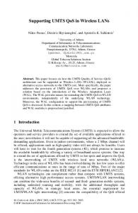
second). Each bucket is filled at a constant rate (r token/s for the former, and p token/s for the latter, where r is the average rate and p the peak rate to be controlled by each token bucket). Each token allows the transmission of one octet of data. When a packet arrives and reaches the head of the arrival queue, it can pass to the second queue only if, at least, the number of tokens available equals the length of the packet, including its header. If not, the packet has to wait for new tokens to be generated. When a packet is transmitted towards the second queue, the used tokens are removed from the first bucket. The second bucket has a similar behaviour. In this model, the first token bucket regulates the average transmission rate, and the second token bucket controls the maximum transmission rate. Also, M is the maximum packet size allowed, while b is related to the maximum burst length that can be transmitted at the peak rate. B. Objectives The results presented in the following section are obtained from a set of simple trials, where each application is used for about a minute with typical conditions. During these trials, packets are captured, with tcpdump, from all interfaces in the testbed. After each trial, the packet capture files are analysed by a specially designed tool. Besides that packet data itself, this tool receives as input a log file with the signalling messages exchanged between the QoS Manager, the NAS module and the RSVP daemon. With this information, it can verify that (1) the traffic that enters the UTRAN is conformant with the negotiated QoS parameters, and (2) the UTRAN honors the negotiated QoS, namely maximum delay guarantees. Another concern is to verify that the overall end-to-end QoS is acceptable. We observe the service and delays curves to assert that applications have their traffic delivered end-to-end with limited delay and losses 2 .
III. T EST F RAMEWORK A. Architecture The test architecture used to validate the QoS framework is presented in Figure 2. There, we can observe the three network elements dealing with IP: TE, GGSN, and the SERVER. IP is here assumed to be the end-to-end service mentioned in [7]; IP uses Secondary PDP Contexts in the UMTS network. IP flows are end-to-end packet flows and, in UMTS, they can be multiplexed in a PDP Context. The regulator R shapes each flow entering a PDP context. TE
SERVER
GGSN Applications RTP
Applications RTP
TCP-UDP
TCP-UDP
IP
IP
IP
R
R (1) (3)
TE (eth0)
(2) (4) GGSN1 (eth0)
Secondary PDP
GGSN2 (eth1)
SERVER (eth0)
IV. R ESULTS In this section some of the more interesting results, obtained during testbed trials, are presented. They take the form of delays and service curves, instead of simply numbers. Results are presented per IP flow. For each flow, two graphics are presented—a service graphic and a delay graphic.
Other
Fig. 2. Test Architecture
The regulator mechanism R is shown in Figure 3. This mechanism consists of two buckets. Each bucket can contain up to a maximum number of tokens (b tokens for the first and M for the
2 Perhaps the delay part has been somewhat sacrificed in favor of losses. In order to reduce the delays, traffic could no longer remain compliant when entering UTRAN, and excess traffic would most likely be dropped.
2
Mobile Summit 2003 Packet arrival of IPFlow streaming-base-downlink
150000 100000
TE GGSN1 GGSN2 SERVER
50000
accumulated packet sizes (bytes)
200000
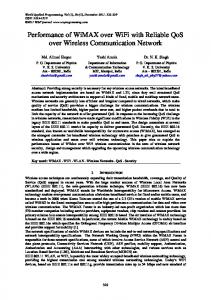
The service graphic displays the time evolution of byte arrival/departure in every network interface monitored. The delay graphics display the end-to-end delay, the UTRAN delay, and the core delay as a function of time. Based on these graphics, conclusions are drawn. It should be noted that, when these results were obtained, the UTRAN lower layers were not fully operational. To overcome this, the UTRAN was replaced by an emulation tool called NIST-Net[6]. For each trial, NIST-Net was configured to emulate the worst-case conditions of the PDP Contexts that would be created during each trial. This way, conformity of traffic entering the UTRAN is detected by observing the UTRAN delays—NistNet will induce an additional delay (besides the configured delay) to packets when the average bitrate passing through it exceeds the configured bandwidth value.
170
180
190
200
210
220
230
Packet capture time (seconds) Packet delays of IPFlow streaming-base-downlink
A. Video streaming
1000 800 600
Core delays UTRAN delays End-to-end delays
200
400
delay (miliseconds)
1200
1400
Audio-video streaming is based on the applications developed by the MPEG4IP group. The audio base layer stream is delivered over UDP and carried in one PDP Context from the Server to the UE. The video enhancement layer stream is delivered over RTP/UDP and carried in another PDP Context from the Server to the UE. The PDP Context to carry audio data has a guaranteed and maximum bitrate of 32kbps. The video PDP Context, on the other hand, is configured with 96kbps of maximum bitrate and no guaranteed bitrate, which means that the video flow has lower delivery priority than the audio flow. 1) Audio: The two plots in figure 4 refer to the audio stream. The 1st delay in the UTRAN emulator is visible in both plots: as a horizontal right shift of the TE curve in the first plot, and directly as the horizontal line at 1000 ms in the UTRAN delay curve, in the second plot. The core delay curve is an almost exact replica of the previous trial, if the different vertical scale is accounted for. Especially important is the fact that the UTRAN delay curve is a horizontal line. This means that the traffic after reshaping does not exceed the bandwidth limits configured in NistNet; otherwise, we would see an additional and variable delay in the UTRAN delay curve. 2) Video: The two plots in figure 5 refer to the video stream. The traffic pattern depicted in the service curves plot is very typical of video streaming. There is an initial peak rate, when the film starts, with a corresponding increased delay followed by a decrease in bit rate and a gradually decreasing delay. The reshaping point is the one responsible for the bulk of end-to-end delay, as expected. It is important to point out that, although the maximum delay of about 8.5 seconds looks bad, it really is acceptable. This delay only affects the time it takes for the stream to start displaying after being requested (which is actually much less than 8.5 seconds); otherwise, it is not visible. The UTRAN delays are steady at one second, which indicates, once again, that the bandwidth limit is not exceeded.
170
180
190
200
210
220
230
Packet capture time (seconds)
Fig. 4. Video streaming: audio service curves and delays
for both directions (UE → Server, UE ← Server). This PDP Context has a guaranteed bitrate of 64kbps. 1) Audio: The two plots in figure 6 refer to the downlink audio stream of video telephony. In the packet arrival plot, we can observe the typical service curve of an audio conversation. There are two fundamental types of periods. One is characterized by a high and steady slope, and corresponds to the period when the user is talking. The other one corresponds to the inactivity periods, when the user is not talking at all—only listening to its conversation peer. In this case, the audio codec automatically detects silence periods, and stops generating packets, which results in a flat, horizontal region of the curve. Although not perceptible on the service curves, there is a delay of ≈100ms in the UTRAN, as can be observed in the delay plot. It is also clear that the core network delay is negligible—a clear indication that the RSVP reshaping is not introducing any additional delay. 2) Video: The two plots in figure 7 refer to the downlink video stream of video telephony. The service curves are very ”interesting”. They show that the application was, once again, generating a much larger bit rate than the RSVP reservation.
B. Video telephony Audio-video telephony is based on VIC and RAT. The video and audio streams are transported over UDP/RTP. Both streams are carried out in the same PDP Context (two flows are multiplexed into a single channel). Only one PDP Context is used 3
Packet arrival of IPFlow videotel-audio-downlink 40000
Packet arrival of IPFlow streaming-enhancement-downlink
35000 30000 25000 20000 15000
accumulated packet sizes (bytes)
TE GGSN1 GGSN2 SERVER
5000
10000
500000 400000 300000 200000
TE GGSN1 GGSN2 SERVER
100000
accumulated packet sizes (bytes)
600000
700000
Mobile Summit 2003
170
180
190
200
210
220
80
230
90
100
110
120
130
Packet capture time (seconds) Packet delays of IPFlow videotel-audio-downlink
60
Core delays UTRAN delays End-to-end delays
20
40
delay (miliseconds)
6000 4000
Core delays UTRAN delays End-to-end delays
2000
delay (miliseconds)
80
8000
100
Packet capture time (seconds) Packet delays of IPFlow streaming-enhancement-downlink
170
180
190
200
210
220
80
230
90
100
110
120
130
Packet capture time (seconds)
Packet capture time (seconds)
Fig. 5. Video streaming: video service curves and delays
Fig. 6. Video telephony: audio service curves and delays
This is an application configuration issue (trivial to fix). The service curves also indicate that there were heavy packet losses. We can conclude this by looking at the end of the curves and asserting that there is a disparity in the final byte count of SERVER/GGSN2 versus GGSN1/TE, which is also an indication that the losses occurred between interfaces GGSN2 and GGSN1, i.e., at the reshaping point. What happened was that the TBF module, which takes care of reshaping, has a large but limited buffer. In this case the buffer has overflowed.
used to log IP packets in relevant network interfaces at the terminal, GGSN and IP server. Using these logs, the new tool was used to evaluate the compliance of the traffic offered to UMTS bearers as well as the service provided by these bearers. Moreover, useful graphics of arrival and service curves as well as of delays could be obtained. By using them, it was possible to identify and solve problems as well as to tune the key QoS parameters. c) The final QoS approach: The development of the Multimedia Testbed Applications over the ARROWS testbed has led us to an interesting end-to-end QoS approach for deploying IP based services over UMTS access networks. From our point of view, this approach has the potential for being reused in more realistic environments. In our approach, UMTS is considered an IP access network supporting IntServ that can communicate with IP DiffServ core networks. For this purpose, a key component had to be introduced at the mobile terminal— the QoS Manager. Using it, the limitations of RSPV in wireless environments, the asymmetry of the UMTS primitives and the aggregation of IP flows over PDP contexts could be solved.
V. C ONCLUSIONS a) The real-time applications: Audio-video telephony was used with success, in the lab. Using a 64 kbit/s channel, two users could communicate efficiently, using these applications. Audio-video streaming was, perhaps, even more interesting to observe, since more bandwidth was available. All these applications were run on normal PCs, with no dedicated hardware and using standard and non-QoS aware applications. b) The traffic analyser: During service tests, the requirement of a new test tool has emerged. Assuming that an UMTS network interface is a standard network interface, tcpdump was 4
Mobile Summit 2003 Packet arrival of IPFlow videotel-video-downlink
80000 60000 40000
TE GGSN1 GGSN2 SERVER
20000
accumulated packet sizes (bytes)
100000
Moreover, when comparing the conversational and streaming classes, the former requires a tight bound on delay and stringent control of the delay jitter. This is mostly due to the fact conversational traffic is symmetric, while streaming is highly asymmetric and therefore it is possible to use buffers for smoothing out jitter. In conversational services, this would increase the delay acceptable for a natural human conversation, turning the communication awkward. In ARROWS, one application representative of each UMTS traffic class was selected: Videoconference (conversational), Video streaming (streaming), Web browsing (interactive) and Email (background). All applications were required to satisfy three characteristics: 1) be widely used; 2) be open source, so that extensions to IPv6 or the incorporation of new QoS features could be easy; 3) have port for Linux. VIC (video conference tool) and RAT (robust audio tool) were selected as departing applications for Videoconference. Although designed for multicast environments, they are configured in ARROWS as point-to-point (unicast). Both applications rely on RTP (Real Time Transport Protocol), the IETF protocol for the transport of real-time data, including audio and video. It can be used for media-on-demand as well as for interactive services such as Internet telephony. RTP consists of a data and a control part. The latter is called RTCP (Real Time Control Protocol). Both protocols use the services provided by the UDP protocol that, in turn, uses IP. VIC supports the H.261 and H.263 video codecs. H.261 is a standard designed for data rates multiple of 64 kbit/s, while H.263 was designed for low bitrate communication (less than 64 kbit/s). RAT supports various codecs, such as G.711 PCM (64 kbit/s), G.726 ADPCM (16-40 kbit/s), LPC (5.6 kbit/s) and GSM (13.2 kbit/s). When used for an audio-video telephony call, these applications generate two real-time and bidirectional IP flows (audio and video) that have to be adequately transported through the UMTS transport services, that is, Radio Access Bearers (RAB) and Packet Data Protocol (PDP) Contexts, as discussed on Section III. For Video streaming it was decided to use a layered coding scheme that generates two streams with base and enhancement information, respectively. The application that is used is the one developed by MPEG4IP project, which deploys video over the RTP/UDP/IP protocol stack. When playing a stream, two unidirectional and real-time IP flows must be transported over the UMTS network. Web browsing at the terminal requires a browser, that is, an HTTP client. Email, at the mobile terminal, requires both POP3 and IMAP clients. The three application protocols (HTTP, POP3 and IMAP) use the TCP/IP stack. No real-time requirements are envisaged for the IP flows they generate. Mozilla was used as departing point for these applications.
100
105
110
115
120
125
130
2500 2000 1500
Core delays UTRAN delays End-to-end delays
500
1000
delay (miliseconds)
3000
3500
Packet capture time (seconds) Packet delays of IPFlow videotel-video-downlink
100
105
110
115
120
125
130
Packet capture time (seconds)
Fig. 7. Video telephony: video service curves and delays
R EFERENCES [1] IST ARROWS project, http://www.arrows-ist.upc.es. [2] 3GPP TS 23.207 v5.3.0, End-to-End QoS Concept and Architecture, March 2002. [3] 3GPP TS 23.107 V5.0.0, QoS Concept and Architecture, April 2001. [4] Sally Floyd, Notes on CBQ and Guaranteed Service, July1995. [5] K. Dovrolis, M. Vedarn, P. Ramanathan, The Selection of the Token Bucket Parameters in the IETF Guaranteed Service Class, Technical Report, Department of ECE, University of Wisconsin-Madison, November 1997. [6] http://snad.ncsl.nist.gov/itg/nistnet/ [7] 3GPP TS 23.107 v3.6.0: QoS Concept and Architecture [8] M. Ricardo, J. Dias, G. Carneiro, J. Ruela, ”ARROWS QoS Framework”, Contribution to the Vision Book 2002, IST Systems Beyond 3G Cluster (SB3G), 31 August 2002. [9] M. Ricardo, J. Dias, G. Carneiro, J. Ruela, ”Support of IP QoS over UMTS Networks”, PIMRC 2002, The 13th IEEE International Symposium On Personal, Indoor and Mobile Radio Communications, 15-18 September 2002, Lisboa - Portugal. A PPENDIX A. Multimedia Applications In UMTS four traffic classes have been identified: conversational, streaming, interactive and background[3]. One main distinguishing factor between these classes is how delay sensitive the traffic is. The conversational class is meant for very delaysensitive traffic, while the background class is delay tolerant. 5