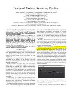
Available online at www.sciencedirect.com
ScienceDirect Procedia CIRP 21 (2014) 75 – 80
24th CIRP Design Conference
An example of visually supported design of modular product families Nicolas Gebhardt*, Tammo Bahns, Dieter Krause Hamburg University of Technology, Denicketraße 17, 21073 Hamburg, Germany * Corresponding author. Tel.: +49 40 42878 4257; fax: +49 40 42878 2296. E-mail address:
[email protected]
Abstract To offer individualized products at globally marketable prices, the Integrated PKT-Approach for Developing Modular Product Families aims to generate high external product variety based on a low internal process and component variety. Specific visualizations are an important factor in the success of this approach. In this paper the Module Interface Graph (MIG) developed at the Institute for Product Development and Mechanical Engineering Design (PKT) is used to show how specific visualization concepts of a product family can help present important information, as well as define module interfaces and boundaries during the modularization of a product family. Two brief industrial case studies are presented to give insight into using the MIG and emphasize potential improvements to visual product representations for developing modular product families in a team.
© 2014 Elsevier B.V. This is an open access article under the CC BY-NC-ND license © 2014 The Authors. Published by Elsevier B.V. (http://creativecommons.org/licenses/by-nc-nd/3.0/). Selection and peer-review under responsibility of the International Scientific Committee of “24th CIRP Design Conference” in the person of Selection and peer-review under responsibility of the International Scientific Committee of “24th CIRP Design Conference” in the person of the the Conference Chairs Giovanni Moroni and Tullio Tolio. Conference Chairs Giovanni Moroni and Tullio Tolio Keywords: Customized and personalized product development; complexity reduction for innovation teams; creative and innovativ design
1. Introduction Markets are becoming more and more global. For manufacturing companies this leads to a global customer base with high individual demands. Meanwhile companies face global competition, resulting in high cost pressure. Companies have to handle the conflict of offering highly variant products at low prices. An increase in external product variety due to individual customizations results in an increase in product and process complexity, a loss of transparency within the company and high complexity costs. Companies have to find a solution to offer a wide and flexible range of product variety while retaining low internal variety of components and processes. A proven product-based solution for this is the strategy of modular product structures. However, while it can lead to reduced complexity in other divisions, e.g. production and logistics, the development of modular product structures is still seen as a major challenge. Using methodical modularization of the product structure, areas of the product are defined as being closely coupled and clearly separated
from each other by well-defined interfaces. Collecting the requirements and allocating them to components for suitable modules are challenging tasks involving stakeholders from all product life phases, such as purchasing and production. This paper presents an overview of the integrated PKTApproach for developing modular product families developed in recent years, starting with an introduction of the four underlying attributes which make the approach unique [1]. One of the core visualizations used in the approach - the Module Interface Graph (MIG) - is explained in detail. The tool is used to simplify collaboration between several design disciplines and company departments within a modularization project. Case studies from industry demonstrate its application and identified potentials of improvement. 2. The integrated PKT-Approach for developing modular Product Families The Institute of Product Development and Mechanical Engineering Design (PKT) developed an approach to support
2212-8271 © 2014 Elsevier B.V. This is an open access article under the CC BY-NC-ND license (http://creativecommons.org/licenses/by-nc-nd/3.0/). Selection and peer-review under responsibility of the International Scientific Committee of “24th CIRP Design Conference” in the person of the Conference Chairs Giovanni Moroni and Tullio Tolio doi:10.1016/j.procir.2014.03.162
76
Nicolas Gebhardt et al. / Procedia CIRP 21 (2014) 75 – 80
the development of modular product families [1] in the preliminary design stage. A product family’s degree of modularity is dependent on combinability of modules, function binding, interface standardization and loose coupling between components [2], [3]. Appropriate utilization of these properties, and therefore modularity, within the product structure has to be archived during the development of a modular product family. Advantageous module concepts depend on functional technical as well as strategic requirements [4] from all product life phases. From a variety-oriented point of view, a product structure with the following product structure properties are desired [5, 6]: x Clear differentiation between standard components and variant components x Reduction of variant components to the minimal variant part x One-to-one mapping between differentiating properties and variant components x Minimal degree of coupling of variant components to other components The integrated PKT-Approach supports product developers and designers during this task. It was created by combining new concepts with adapted ideas from existing literature and approaches [7], and has been validated in multiple industry projects [8]. The approach consists of a set of method units that consider product and process views (Fig. 1).
3. The Module Interface Graph (MIG) The use of task-specific visualization tools is a major factor in the success of all methodical units of the approach. Specific visualization enables multiple experts from different company departments (e.g. R&D, and marketing) to integrate by providing an overview as well as view-specific details. Working with visualization during the development of modular product families is illustrated by work with the Module Interface Graph (MIG, Figure 2). The visualization was first developed in 2008 by Blees [2]; since then it has been used in more than twenty industrial projects and thirty student projects. During this time the visualization was further developed. The MIG is a schematic 2D graph of a product family and its components. It arranges only the information that is essential for deciding modular structures. It complements the product documentation typically used in product development (e.g. CAD models, bill of materials or function structures) by supporting communication and decision-making in a trade-off situation between the stakeholders of modularization.
product family
Structural connection Electrical power Mechanical power Media flow Flow (directional) Flow source/sink Optional flow Component (standard) Component (variant) Component (optional) Component (variant and in variant quantity) Component (optional and in variant quantity)
Fig. 2: Example of a Module Interface Graph (MIG) [9]
Fig. 1. Overview of the Integrated-PKT Approach for developing modular product families [1]
Four underlying attributes make the approach unique. x The approach is structured as a set of combinable method units each designed for a specific task. Combining them allows flexible and case-specific support. x It emphasizes redesign, modification and new design of components to reduce product variety. x The approach is workshop-based to integrate product knowledge from different disciplines. x Multiple specially developed visualization concepts are integrated to foster discussion in project teams. Section 3.2 shows the combined application of two units, "Design for Variety" [5] and "Life Phase Modularization" [2]. A broader overview and in-depth explanation of the approach’s method units can be found in [9].
The MIG contains all essential and optional components of the product family along with their approximate location, shape and size. All components are labeled with their name or an abbreviation to clearly identify components. As described in detail in Section 3.2, it indicates whether the same component can be used in all members of the product family or if variants of the component are required (Fig. 2). Flows connecting the components via interfaces represent important information about the internal couplings within a product family and are therefore included in the MIG. Flow types, directions, etc. are differentiated by shape and color (Fig. 3).
77
Nicolas Gebhardt et al. / Procedia CIRP 21 (2014) 75 – 80 Legend of flow directions a) Nondirectional flow b) Directional flow C1
C2
C3
d) Flow junction C9
e) Flow sink
C10
C12
C4
Legend of flow types c) Bidirectional flow C5 C6
Electrical power C13
C11
C15
C14
g) Flow out of the system C16
Mechanical power Media flow
...
f) Flow into the system
Structural connection
Fig. 3: Legend of the representation of flows in the MIG, based on Blees [2]
The MIG comprises cross functions as well as functions specific to the methodical steps within the integrated PKTApproach to which it is assigned. 3.1. Cross functions of the MIG
elements show similarity to real product geometries [11, 12]. x Product family view: A MIG represents an entire product family and therefore counteracts the risk of focusing too much on a single variant. It emphasizes variant components as the typical reason for variant processes and extra complexity costs. Analysis of product variety is enhanced by using colors and line types to indicate variety of the components. 3.2. Methodical steps utilizing the MIG The MIG is used as a main tool within the core units of the integrated PKT-Approach “Design for Variety” and “Life Phase Modularization” (Fig. 5). Goal setting
Cross functions of the MIG support general understanding and communication of information, ideas and concepts in modularization projects. x Ensuring interdisciplinary work: The MIG is a relatively simple visual concept that only shows the shapes of components and connecting flows. Broad understanding and communication is enhanced by showing information that is not specific to only one department or discipline (Fig. 4).
Reduction of internal variety
2
3
4
5
1 Varietyoptimized components 1. Definition of goals 2. Analysis of external variety
Modularization of product family concept
Result
MIG as main visual tool 6
Presentation & discussion
7
3. Analysis of internal variety 4. Derivation of variety optimized component concepts 5. Evaluation & choice of product family concept
6. Strategic modularizations for all relevant product life phases 7. Combination of modularizations and derivation of the modular product structure
Fig. 5. Use of the MIG within the main methodical steps of the integrated PKApproach [1]
Fig. 4. Interdisciplinary workshop
x Focusing level of abstraction: to focus attention at a suitable level of abstraction the MIG displays only previously chosen components of the product family. Working on this more abstract visualization of the product family as a boundary object, especially within workshops, prevents attention and discussion on subtle details. Modularization is of most interest in preliminary design phases, when working on 3D-CAD, for example, could encourage excessive attention to detail. x Preserving the designer’s view: In contrast to many visualization concepts based on node-link diagrams, the MIG shows the product structure with general shape and arrangement of the components. Other node-link diagrams, like MOFLEPS, often display components as anonymous shapes identified by names and sometimes simple icons [10].The MIG preserves arrangement and shapes and thus ensures an overview and orientation, resulting in faster understanding and information gain, e.g. spatial consequences of module concepts can be evaluated more quickly. In engineering work, a visual modeling approach supports the designer in solution finding and communication of concepts, especially if the displayed
x Analyzing internal variety: Drawing the MIG is an important step in the decomposition and assessment of internal variety. Greyscale and line types are used to emphasize the variety of the components, as shown in Fig. 6. To clearly differentiate between standard components and variant components, only standard components are displayed in white. All variant components are displayed in grey, making them easily visible. Advances in the actions of variant optimized design can be displayed by beforeand-after comparison. Categories of component variety standard optional variant
Combinations optional & variant variant & differing number optional & differing number
differing number
...
Fig. 6. Visual coding of component variety in the MIG
x Deciding desired modularizations: deciding and documenting the desired modularizations is first carried out separately for each product life phase and visualized with colored shadings within the MIG. The general approach of the MIG as a relatively uncluttered visualization leaves drawing space for grouping components by background shades or by drawing colored boundaries using a marker pen (Fig. 7).
78
Nicolas Gebhardt et al. / Procedia CIRP 21 (2014) 75 – 80
4.1. Practical Training on the integrated PKT-Approach – Design for Variety and Life Phase Modularization of a product family of vacuum cleaner robots In advanced training workshops on the integrated PKTApproach (Fig. 5) the product family of vacuum cleaner robots is redesigned by participants. This product family is a highly suitable training case study because of its variety, complexity and “incentive” character. Since early 2012 it has been successfully used for training sessions with engineers from industry and students of mechanical engineering [13] Fig. 7. Drawing modules using colored boundaries
x Solution finding in aligning life phase modularizations: Different requirements of the product modularization of life phases are integrated and aligned. The MIGs of all life phases are used to communicate their requirements and to find solutions for a harmonized modularization of the product family (Fig. 8).
development
sourcing
production
sales
use
recycling
Fig. 9. Product family of the vacuum cleaner robot, providing different cleaning functions and operation features [www.irobot.com]
Before starting with a MIG, the external variety is analyzed using another visual tool, the Tree of external Variety (TeV) [7]. The MIG is then used to display and discuss the variety of product components (Fig. 10). Nearly all components of the robot are variant, leaving only the drive mechanics as standard components.
filter
outher housing
Product life phase
bin wheel circuit board right
Based on experience, the MIG is very versatile and suitable for application independent of the industry sector. The MIG has been used in different industries, e.g. conveyance, aviation, measurement instrumentation and filling stations, with company sizes ranging from small companies to multinational corporations. Depending on the case, representatives from product planning, marketing, development departments, purchasing, production planning and service worked individually or in workshops using the MIG. [7] Two case studies will be presented in this section. The first is on an advanced training program at the Institute PKT for engineers from industry [13]. It gives insight into the MIG functions in the main steps of the integrated PKT-Approach. The case covers the variety-oriented redesign and life phase modularization of a product family of vacuum cleaner robots. The second case study is on current frontiers of using the MIG as a tool, e.g. the size of the product in terms of number of components that can be handled during a modularization project. The second case study presents the current analysis of a variety of passenger elevators.
right wheel motor
wheel circuit board left
left wheel motor
brush II brush housing
right wheel mechanics
side brush motor
inner housing piezosensor
side brush circuit board
brush I brush circuit board
brush motor
brush gear
4. Application cases of the MIG
rotor motor
rotor mechanics
Fig. 8. Poster for aligning demands of product life phases on product modularization, based on Blees [2]
left wheel mechanics
mainboard user-interface side brush housing side brush battery caster wheel
Fig. 10. Module Interface Graph of the cleaning robot, with flows of dirt/air, information, mechanical and electrical energy in different colors.
After improving the product family structure and design using the methodical unit “Design for Variety”, a before-andafter comparison can be visualized by using MIGs (Fig. 11) and the Variety Allocation Model (VAM) [1]. The new concept enables the standardization of many components shown in the MIG by their white color.
Nicolas Gebhardt et al. / Procedia CIRP 21 (2014) 75 – 80
filter
Rotor-EMotor
rotor motor
rotor mechanics
4.2. Modularization of a passenger elevator product program
Design for Variety
outher housing
Füllstandsensor
bin
Filter
Schmutzcontainer
wheel circuit board left
brush gear
brush housing
brush I brush motor
Rotormechanik Bürstengehäuse
Optischer Sensor
Motorplatine
Bürste II
BürstenE-Motor
left wheel mechanics
Bürste I
mainboard user-interface
Düse
User-Interface
MotorMotorplatine platine
Platine/ Steuereinheit
Motorplatine
Seitenbürsten E-Motor
side brush housing side brush
Seitenbürste
battery
Kontaktsensor
Akku Bug -rad
caster wheel
Wegsensor
Hindernissensoren
standard
Radmechanik links
Pumpe
Düse
Radmechanik rechts Rad-E-Motor rechts
brush circuit board
side brush circuit board
Gehäuse innen
left wheel motor
brush II
right wheel mechanics
side brush motor
inner housing piezosensor
Rad-E-Motor links
wheel circuit board right
right wheel motor
Abgrundsensoren
variant
Fig. 11. Before-and-after comparison of the methodical step “Design for Variety” showing increased number of standard components by color
The next methodical unit after Design for Variety is Life Phase Modularization (Fig. 5). Developers use the MIG to define, display and discuss the ideal modularization for each product life phase with the applicable departments of the company. During training, groups of two to three engineers act as the company departments working on the life phase specific modularizations (Fig. 12). Bürste I Bürstenplatine
Seit Seitenbürsten -platine
SeitennbürstenenE-Motor tor
Platine/ Steuereinheit
User-Interface Seitenbürstengehäuse
BürstenE-Motor
Filter
Gehäuse außen
Radmechanik nikk linkss
Bürste II Bürstengehäuse
Bürste I Bürstenplatine
Seitenbürsten -platine
SeitenbürstenE-Motor
Platine/ Steuereinheit
Radplatine links
Radplatine Piezorechts sensor
Rad-EMotor rechts Radmechanik rechts
BürstenE-Motor
User-Interface Seitenbürstengehäuse
Gehäuse innen Rad-EMotor links
Rad-EMotor rechts
Radmechanik links
SeitenbürstenE-Motor
Platine/ Steuereinheit
Bürste II Bürstengehäuse
Bürste I Bürstenplatine
Seitenbürsten -platine
Rad-EMotor links
Radmechanik links
Platine/ Steuereinheit
Seiteneitenbürste ürste Akku
Akku
Bug -rad
Bug -rad
Bug -rad
Production
Sales
Use
Tastschild
Tastschild
MIG
BürstenE-Motor
User-Interface Seitenbürstengehäuse
Seitenbürste
Akku
Bug -rad
Tastschild
Radplatine links
Radplatine Piezorechts sensor
Radmechanik rechts
Akku
Purchase
Gehäuse außen
Rotor-EMotor
Rotormechanik chanik Schmutzbehälter
Gehäuse innen
Rad-EMotor links
Seitennbürste
Seitenenbürste te
Development
Bürstentenuse gehäuse
Bürstengetriebe
BürstenE-Motor
User-Interface Seitenbürstengehäuse ehäuse
Radplatine links
Bürste II
RadRad m mechanik rechts
Bürstengetriebe
Bürstengetriebe
Bürstenplatine
Radmechanik hanikk links
PiezoRadp Radplatine rec rechts sensor
Rad-EMotor rechts
Rad-EMotor links k
Rotor-EMotor
Rotormechanik Schmutzbehälter
Gehäuse innen
Bürste I
Seitenbürsten -platine
Rotor-EMotor
Rotormechanik Schmutzbehälter
Radplatine links
Bürste II
Seitenbürsten-E-Motorr
Filter
Gehäuse außen
Gehäuse außen
Rotor-EMotor
Gehäuse innen
Bürstenengehäuse se
Bürstengetriebe
Filter
Filter
Rotormechanik Schmutzbehälter
Radplatine PiezoR rechts sensor
Rad-EMotor rechts RadRad mechanik m rechts
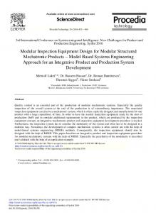
The second case study is taken from the research project ModSupport, which is funded by the Federal Ministry of Education and Research of Germany in cooperation with LUTZ Elevators and the Hamburg University of Technology. The project aims to develop a modular set of configuration modules for highly individual passenger elevators. Elevators constitute a highly variant product which has to be tailored to the specific building construction, design and functional requirements. A diverse and flexible modular concept is needed to fulfill customer requirements and keep internal complexity low (mainly in design and assembly times). During the stage of analyzing internal variety (step 3 in Fig. 5) a MIG is used to display the vast number and variety of components. A very important point at the beginning of a modularization project is abstraction decomposition to a suitable level independent of the prevailing product structure, e.g. from the bill of materials [1]. The MIG strongly supports this level of decomposition (Fig. 14).
Tastschild
Network diagramm
Fig. 12. Deriving modularization concepts for each product life phase using the MIG and network diagrams, e.g. the purchase phase shown here
The final and most productive step of life phase modularization is the alignment of the life phases and their specific ideal modularization concepts. This methodical step is supported by a visual tool called Module Process Chart (MPC). Again, the MIGs of all life phases provide additional aid in this step by supplying detailed information about the life phase’s modularizations (Fig. 13). For example, sourcing modularization can be aligned with assembly module requirements, leading to fewer part numbers.
BürstenE-Motor
Rad-EMotor k links
Radhanikk mechanik links
Platine/ Steuereinheit
Development
Rad-EMotor rechts
PiezoRadp Radplatine rechts sensor rec Bürste II
RadRad mechanik m rechts
SeitennbürstenenE-Motor tor
Bürstentengehäuse use
Seit Seitenbürsten -platine
Bürste I Bürstenplatine
User-Interface Seitenbürstengehäuse
BürstenE-Motor
Rad-EMotor links
Radmechanik nikk linkss
Platine/ Steuereinheit
Rad-EMotor rechts
Radplatine Piezorechts sensor Bürste II
Radmechanik rechts
SeitenbürstenE-Motor
Radplatine links
Bürstengehäuse
Seitenbürsten -platine
Bürste I Bürstenplatine
User-Interface Seitenbürstengehäuse
BürstenE-Motor
Platine/ Steuereinheit
Seitenbürste
Seitennbürste
Seitenente bürste
Gehäuse innen Rad-EMotor links
Radmechanik links
Rad-EMotor rechts
Bürste II Bürstengehäuse
Seitenbürsten -platine
Bürste I Bürstenplatine
User-Interface Seitenbürstengehäuse
Akku
Akku
Akku
Bug -rad
Bug -rad
Bug -rad
Production Tastschild
BürstenE-Motor
Rad-EMotor links
Radmechanik links
Platine/ Steuereinheit
Seiteneitenbürste ürste
Bug -rad
Tastschild
Radplatine links
Radplatine Piezorechts sensor
Radmechanik rechts
SeitenbürstenE-Motor
Akku
Purchase
Gehäuse außen
Rotor-EMotor
Rotormechanik chanik Schmutzbehälter
Gehäuse innen
Bürstengetriebe
Bürste I Bürstenplatine
User-Interface
Radplatine links
Bürstengetriebe
Bürste II Bürstenense gehäuse
Seitenbürstenehäuse gehäuse
Filter
Gehäuse außen
Rotor-EMotor
Rotormechanik Schmutzbehälter
Gehäuse innen
Radplatine PiezoR rechts sensor
Seitenbürsten -platine
Rotor-EMotor
Rotormechanik Schmutzbehälter Radplatine links
Bürstengetriebe
Rad-EMotor rechts RadRad m mechanik rechts
Seitenbürsten-E-Motorr
Filter
Gehäuse außen
Gehäuse außen
Rotor-EMotor
Gehäuse innen
Bürstengetriebe
Filter
Filter
Rotormechanik Schmutzbehälter
Sales Tastschild
Use Tastschild
Module Process Chart (MPC)
Fig. 13. Alignment of the life phase specific modularizations, using the MIGs, giving additional information for the life phases
Fig. 14. Clipping from the MIG of LUTZ passenger elevators
4.3. Experiences and feedback from case studies To date, MIG applications range from student lectures to industry projects. A document analysis was conducted using the existing project files from 29 student projects conducted with industry partners using the MIG (including nine companies and 22 product families). Initial results from an interview study currently being undertaken with engineers in industry are included in the following results (five interviewees from four additional companies). Integration of information specific to company and project Case studies showed that in many projects additional helpful information was available. Even more importantly, many projects aimed for target figures more related to cost and effort than just reducing variety. For example, the case study in Section 4.2 aimed to reduce design efforts per customer order. The MIG shows type of variety, product shape and couplings. These figures represent the most important information for a modularization task; however, a
79
80
Nicolas Gebhardt et al. / Procedia CIRP 21 (2014) 75 – 80
project may be aiming for other targets. Variety within the modular product family, for instance, could be further differentiated to distinguish between components with static variety and components with dynamic variety that changes due to the use of adaptive modules or facelifts during the product life cycle. This results in the need for sophisticated concepts to integrate other important information into the visual tool without compromising their functionalities. Better understanding of visual representations If visual tools equal the tools and documentation already used in a company, designers tend to accept, understand and use them more efficiently (an attitude often stated in interviews is “not another tool please”). Concepts for adaption of visual representations to companies and departments can support this. Visual representations need to provide links to product shapes for better understanding and concept communication [11, 12]. Lists, tables, matrices and many node-link diagrams are often used in similar methods, supporting the design of product variants but missing the fast recognition of components by visual representations of their real shapes. Use in workshops and as a communication object Working in interdisciplinary workshops means combined display and analysis of information from many different departments and domains. To support communication and mediation between people from different backgrounds within a company, visual representations have to fit users’ conventions and comprehension. A systematic approach of marking all visual elements with their source or domain would enhance understanding of influencing factors, traceability, effects and responsibilities. Layout variety The variety of a product family is sometimes limited not just to the type and number of variant components. The elevator from Section 4.2, for example, can feature completely different basic setup layouts, leading to variety of component locality. This does not compromise component specification but interfaces would have to be designed individually. Visualizing different positions of components in the MIG would be a promising adaption. Interface specifications The MIG shows the position of interfaces, the participating components and the kind of connecting flow, but not the interface itself or its aspects, such as combinability, propriety, specifications and capacities. Some companies used interface propriety as the main modularization strategy for preventing or intentionally allowing the use of modules from third party manufacturers. They were missing the necessary information. 5. Conclusions and further research The modularization of product families is a task involving the integration of information and requirements from different company departments. The integrated PKT-Approach offers methodical support for these tasks to product development. It incorporates a set of visual tools that enable analysis,
discussion, improvement and alignment of modular and variant product structures. The Module Interface Graph (MIG) is one of the main visual product representations within the approach. Simple visualization of product components, along with their variety and connecting flows, enables the focus to be at a suitable level of abstraction, providing the basis for better communication in a project team and across departments. Industry case studies illustrate strengths and potential for improvement [12], some of which are applicable to other visual tools for developing modular product families. Current research includes conducting interviews with engineers in industry, as well as researchers and consultants who develop concepts for visual representations. The results will provide a basis for the development of a set of improved visualization concepts for the integrated PKT-Approach, as well as a methodical procedure for the development and adaption of task-specific visualization concepts. References [1]
[2] [3]
[4]
[5] [6]
[7]
[8]
[9]
[10]
[11]
[12]
[13]
Krause. D., Eilmus, S., Jonas, H., 2013. Developing Modular Product Families with Perspectives for the Product Program. CIRP Design 2013, Bochum, Germany. Blees, C., 2011. “Eine Methode zur Entwicklung modularer Produktfamilien”, TuTech Verlag, Hamburg. Salvador, F., 2007. Toward a Product System Modularity Construct: Literature Review and Re-conceptualization. IEEE TEM, Vol. 54, No. 2 Jiao, J.J.,Tseng, M.M., 2000. Understanding Product Family for Mass Customization by Developing Commonality Indices. (J ENG DESIGN, Vol. 11, No. 3, 2000. Kipp, T., 2012. Methodische Unterstützung der variantengerechten Produktgestaltung. Hamburg, TuTech Verlag Krause, D., Eilmus, S., 2011. Methodical Support for the Development of Modular Product Families, in “The Future of Design Methodology“ H. Birkhofer, Editor. Springer, Berlin pp. 35–45. Krause, D.; Ripperda, S.: An assessment of methodical approaches to support the development of modular product families, 19th International Conference on Engineering Design (ICED13), Seoul (2013) Eilmus, S. et al., 2012. Evaluating a methodical approach for developing modular product families in industrial case studies. In Marjanovic D. (ed.), Proceedings of DESIGN 2012, Zagreb, pp. 959–968. Krause D. et al., 2013. Integrated Development of Modular Product Families: A Methods Toolkit. In “Advances in product family and product platform design” T.W. Simpson, J. Jiao, Editors. New York, pp. 245-269. Maurer, M., Boesch, N.-O., Sheng, G., Tzonev, B., 2005. A Tool for Modelling Flexible Product Structures – MOFLEPS. ICED 05, the 15th International Conference on Engineering Design, 15.18.08.2005, Melbourne, Australia. Mortensen, N.-H., Hansen, C., Hvam, L., Andreasen, M. M., 2011. Proactive modelling of market, product and production architectures. International conference on engineering design, 15 18 august 2011, Copenhagen, Denmark. Gebhardt, N., Beckmann, G., Krause, D., 2012. Product Family Models and Knowledge Transfer Support for the Development of Modular Product Families. 9th Norddesign Conference, Aalborg, Denmark. Krause, D., Ripperda, S., Gebhardt, N., Eilmus, S., Hackl, J., Beckmann, G.: Workshop on modularization methods. Research training for engineers, 5th and 6th of October 2013. TUHH, Hamburg, Germany