Design of Modular Rendering Pipeline ´ ston∗¶ , Csaba Csuprai†¶ , Juraj Onderik‡¶ and Roman Durikoviˇ ˇ Tom´asˇ Agoˇ c§¶ ∗ Abyss
¶
Studios Ltd., 811 06 Bratislava, Slovakia e-mail:
[email protected] † Abyss Studios Ltd., 811 06 Bratislava, Slovakia e-mail:
[email protected] ‡ Abyss Studios Ltd., 811 06 Bratislava, Slovakia e-mail:
[email protected] § Faculty of Natural Sciences, University of Saint Cyril and Metod, 917 01 Trnava, Slovakia e-mail:
[email protected] Faculty of Mathematics, Physics and Informatics, Comenius University, 842 48 Bratislava, Slovakia
Abstract— From the user’s point-of-view, current graphics systems have a limited modularity of rendering pipelines. Users cannot assemble a custom rendering algorithm. In this paper, we propose a modular component based rendering pipeline with concepts of visual programming. We briefly define a general module-based architecture for visual programming in graphics systems focusing on rendering pipelines. We suggest improvements by a definition of new connection link types, which reduce the complexity of the modular scheme representing a particular rendering algorithm. Furthermore, we extend the existing logic of the scene by defining the rendering process as a scene element. We discuss the advantages and disadvantages of our approach, and state particular fields worthy of application. Presented ideas are the results of our analysis. The respective prototype application is still in development.
I. I NTRODUCTION Many modern graphics systems offer possibilities for modeling, animation and rendering. Some of them are designed to excel only on a particular field, for example a specialized modeler [1]. Other systems aim to be a versatile for many scenarios [2]. Either way, with the goal of creativity, the asset of every application can be measured by the potential of the user interface or the flexibility and extensibility of the package by additional programming. Based on our best knowledge, there is no user-oriented graphic system that would allow roughly the same level of customization for rendering as it provides for modeling or animation. Many applications have in-house developed modular and object-oriented architectures, but still use a simple hard-coded or a pluggable renderer. The latter can only be parameterized by the user (e.g. set-up of image resolution, accuracy, memory-usage, etc.), but cannot be assembled by the user using relatively primitive components within the application. Usually, neither can it be done by the programmer, because the renderer’s API often allows only custom shader implementations with given restrictions (e.g. 3d graphics). We consider such renderers as fixed or closed. The major factor that contributed to the current unsatisfying state of high-end rendering pipelines, besides the proprietary
code, is the vast demand for fast photorealistic or perception based rendering. This leads to improvement of well-tried methods and to specialized research in this area, but only to a poor diversity. Mastering photorealism is definitely a big milestone for the computer graphics industry, but the possibilities of other useful and contributive visualization methods are immense. We think of the fixed and closed pipelines as of a limitation for the creative artistic expression and workflow. Besides that, every user is hindered in the process of learning the actual functionality behind the rendering algorithms, because the renderers are often monolithic. Within the scope of this paper, we outline the concept of a modular rendering pipeline that could be altered by the user in an intuitive and friendly way, based on the concept of visual programming. Although we can find this idea in various specialized graphics applications (such as image and video processing [3]; see Figure 1) or parts of larger graphics systems (e.g. material definition, animation and procedural modeling), the currently handled domain is only a semantically limited set of data flows and relations. Designing an arbitrary rendering pipeline ranging from simple line drawing, through scientific visualization to experimental physically correct illumination, in a comprehensible user-editable visual scheme, is far more challenging.
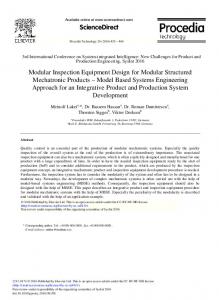
Fig. 1. Our previous implementation of user-editable image processing dataflow. We suggest the visual programming paradigm for using in any rendering pipeline of any complexity.
The term modular visualization environment (MVE) de-
scribes largely the topic we are discussing, but MVE is usually used with scientific visualization and almost never with photorealistic rendering or any other consumer-oriented rendering. Further, recent works [4], [5] refer to the term ”componentbased rendering”, which describes selective integration or computing of components of lightning models during shading and light propagation. In our work, we are using the term modular or component-based rendering pipeline, because the rendering pipeline is decomposed to components and can be reassembled by the user. This paper is divided as follows. In the next section II we present previous work done in the area. In section III we present a model of general module-based architecture. In section IV we discuss some aspects of the module-based rendering pipeline. In section V we present further applications of user-editable rendering pipelines. In section VI we conclude and in section VII we describe the possible future work. II. P REVIOUS W ORK A simple modeling, animation and rendering system was developed by [6]. It is based only on a set of transforming filters connected through pipes in UNIX. Although minimalistic, the user has uniform control possibilities through the whole system. Extensive research work motivated by the problem of fixed rendering pipelines was conducted in the previous decade [7]. With the advent of object-oriented programming as mainstream application development method, this paradigm was applied to complex photorealistic rendering [8], [9], [10]. Although the advantages and necessity of an open rendering systems is clearly stated [11], besides the coding no user interaction, is considered. Visualization Toolkit (VTK) [12] is a well known example of scientific visualization library but it does not support visual programming. An object-oriented GUI was developed for this library, but the toolkit was not suitable for on-the-fly editing [13]. An interesting system based on VTK with interactive optimization of rendering parameters was developed by [14]. IRIS Explorer is a modular scientific visualization environment [15] with visual programming concept. It enables the user to interactively place and connect modules. This system is close to our idea. [16] developed a system as an educational environment for graphics lessons based on IRIS Explorer, which consisted of examples how to modify rendering pipelines. The author states the limitation of the base system, like unidirectional dataflow, slow speed caused by small data batch processing and also non-trivial costs for the proprietary software. Lighting Networks developed by [17] were supported by a visual programming user interface. Modules were distinguished as global (light propagators) and local (operators). The system is considered as a designing tool for lighting algorithms, but does not cover a general pipeline. III. M ODULE - BASED A RCHITECTURE The majority of today’s complex business and scientific processes are usually described by some graph based repre-
sentation (e.g. flow-graphs, asynchronous networks, etc.). This allows a quick insight into the specific problem domain and provides clear visualization of the overall process. In our application, we consider the module based architecture as hierarchy of directed graphs called schemes with nodes being modules and oriented edges being connection links. Communication along the graph can be synchronous (data oriented) or asynchronous (query oriented) depending on the specific type of connection link. In the following paragraphs we give a more in-depth explanation of the proposed module based architecture and further describe its application to the rendering pipeline. A. Modular Scheme Description To solve the opposing objectives of modeling low-level algorithmic and high-level communication scenarios, we hierarchically and functionally organize modules into schemes. Each scheme is defined by its input, output ports and the internal network of several interconnected modules. Therefore schemes comprise a logical and functional subpart of the overall modular architecture. Moreover schemes can be reused as scheme modules within other schemes see Figure 2.
Fig. 2. Module-based Architecture Description. Basic elements of the proposed module-based architecture can be categorized into: Input, Output port, Module, Scheme module, Template Module, Data-flow link, Query link and Template link.
B. Module Description Modules represent the essential units of overall functionality. From the user’s perspective they are considered as atomic operations and thus the internal implementation is usually hidden. To ensure a scalable depiction of simple data processing and a high-level distributed communication, modules must fulfill several basic restrictions. First, they must be simple enough to accomplish even the most elementary tasks, such as matrix and scalar operations, often occurred in graphics algorithms. However in practice the structure of low-level algorithms will not be presented in
a module based fashion, otherwise the resulting system would not be much simpler compared to the actual implementation (source code) and performance issues would arise. Second, modules must be sophisticated enough to provide complex high-level functionality. So users can focus on solving tasks and prototyping, rather than wasting time while building systems from low-level, elementary components. Therefore we define a module by specifying its operation (function) and necessary input and output ports similar to [18], see Figure 2. Ports serve as connections endpoints for the connection links and define allowed/supported communication protocols (interfaces). Complex modules usually contain a number of input and output ports, therefore we suggest the user interface for editing modular schemes should be able to show or hide ports if necessary.
As a better visualization of this concept consider the following figure. It depicts the definition and usage of a highlevel template scheme called ”my irradiance sampler”, see Figure 3. The ”square sampler” represents a template input port responsible for delivering and instancing the placeholder module ”square sampler” from outside the scheme definition.
C. Connection Link Description The overall communication is set along connection links. Each link simply defines a connection between an output and input port and thus represents an association between respective components. Again, simple and complex scenarios require different types of connection links. Therefore we define the following three basic categories. Data-flow Connection Links This category represents the majority of connection links. Given a common protocol a data-flow connection link simply transfers streams of data from the output to the input port. Moreover some particular types of a data-flow connection links can further implement data compression, encryption or similar operations. Query Connection Links In more sophisticated, high-level scenarios the previous type of connection links is insufficient. This occurs when modules need to establish a more complex, usually asynchronous, communication instead of a simple data transition/transfer. In such scenarios the ”client” module first queries the ”server” module for allowed protocols and then requests any necessary information using a supported protocol. Template Links Sometimes it is desired to quickly prototype a scheme by simply substituting a particular module with a different one. This can be easily achieved by duplicating the scheme and directly replacing the module. However introducing template links can produce more reusable architecture. Instead of directly replacing modules inside copies of schemes, we create only one ”template” scheme with ”template” input ports. Now we can use the ”template scheme module” and connect it with the desired modules, which are used to replace the functionality of placeholder modules found in the scheme inside the module. Placeholder modules serve as helpers while designing the scheme, when the functionality is not known yet. This approach further hides the internal functionality of the ”template scheme” and provides another level of ”metaparameterization” and thus better comprehension.
Fig. 3. Example definition of a template scheme ”my irradiance sampler” and its application within a superior scheme.
IV. M ODULE - BASED R ENDERING P IPELINE Although the leading 3D production tools have a highly modular architecture it is usually extensible only writing new scripts or plug-ins. Developers can benefit from their highquality object-oriented API. However, only a few of them (e.g. Maya, Softimage) really expose this rich collection of features to artists in clear and comprehensible visual form. However mostly this applies only to modeling, shading and animation. (e.g. Hypergraph in Maya). Although highly parameterized, the rendering subsystem still suffers from the closed and monolithic pipeline. Therefore artists are restricted to the typical workflow of modeling, animation, shading, lighting and
finally rendering. To point out the key problems imagine the following example. Suppose we want to render a simple scene where the camera is approaching a person watching a movie on a television. The closer the camera is to the television the more details can we see. Using a static rendering pipeline we can usually achieve this effect only by rendering the movie first, save it to disk and then use it as a texture in a second scene, containing the television, which is to be rendered separately. The obvious problem is that we had to choose a fixed resolution when rendering the movie. However this is inefficient in our example scene, since in the beginning the camera is far from the television and thus in the final render the screen represents only a few pixels. On the other side, as the camera approaches, the screen covers most of the space in the rendered image. If we use only a low resolution for rendering the movie, we will experience aliasing artifacts. Imagine we could render the scene and the movie in the television at once, using a single rendering pipeline, which would replace the two previous rendering passes of an obviously less flexible renderer. Therefore in each frame of the final render we can adaptively choose the resolution for rendering the movie. Furthermore, assuming the use of raytracing algorithms the ”movie renderer” can shoot rays only for pixels used in the final image. Such approach considerably reduces the computation cost while provides better quality.
prototyping of special rendering and post-production effects. Further we are not restricted in connecting modules only from one domain, i.e. we can combine animation and rendering and construct a new ”animated” rendering pipeline. The implicit decomposition of the algorithms to modules asynchronously communicating along well-defined connections makes the implementation in parallel environments using specialized hardware (e.g. programmable graphics cards) more straightforward. This is possible without changing the existing structure of the designed graphics process. Standard parallelism is also possible through flow control [19] or by distributed queries [5]. Such modularity will naturally lead to several performance drawbacks. We estimate an efficient implementation in C# and .NET framework will not reveal more than 20-25% slowdown comparing to a fixed monolithic implementation. This might seem first too disappointing, however parallel architectures can greatly increase the speed of the overall process. It is therefore upon the particular implementation to choose the right level of modularity and thus properly control the tradeoff between flexibility and performance. Notice, that similar parallel approaches have been proposed using component-based rendering [5] and lighting networks [19]. Another important aspect emerging from the modular structure is the ability of dynamic modifications and real-time debugging. Users can simply attach several inspecting modules and monitor performance or other indicators. We must also consider the amount of effort invested when learning to work with such modular system. A number of contemporary applications implement their functionality in a modular fashion and expose it to the user. Therefore we believe that the average user is already familiar with some modular architecture and will not have difficulties to use and build upon a system as the one we propose. Finally we suggest the system to be freely obtainable by a relevant scientific and artistic community. This would quickly speed up the development, deployment and assure active maintenance. V. A PPLICATIONS The proposed system is designed in a way it minimizes the drawbacks we identified while examining fixed rendering pipelines, enabling the system to be applied in various areas. We will discuss some of them in the following sections. A. Algorithm prototyping and development
Fig. 4. A schematic comparison of fixed and open rendering pipelines in a complex rendering scenario. Top: Multiple passes of a fixed pipeline. Bottom: Single modular scheme of a user-editable rendering pipeline.
In general this strategy can simply combine various rendering styles within one scene and thus reduce the final postprocessing or even redundant rendering. The idea of open and modular rendering pipeline is briefly depicted in Figure 4. Applying the proposed module based architecture to the rendering pipeline can further decompose the monolithic kernel into independent modules and thus significantly speed up
The design of new algorithms is achieved by reconnecting, modifying, appending or removing components from an existing scheme. In cases where modification of the scheme is not sufficient (e.g. interfacing with an external system is needed) users can explicitly implement their own components and own types of connections. There are no constrains neither on the number nor on the types of components or connections. The reuse of existing modules suggests itself and only minimal coding is necessary. This approach requires a rich library of modules containing useful and well-known algorithms.
Considering the amount of required source code, the length of the implementation should be comparable with the length of implementation in any other, well-designed system with rich programming interface. Additional coding overhead is caused a) by providing connections enabling the new component to connect and to interact with the rest of the system, and b) by conforming to the component-oriented implementation, which may require the modification of the original algorithm. We advise to generalize all programs to an abstract form and to use as few constrains as possible. For example relativistic rendering like in [20] should be possible in the system with roughly the same modules as in a standard 3D renderer. Sharing existing schemes amongst researchers and developers is essential of fast prototyping. In such case, implementation time of improved methods is reduced. Benchmarks and testbeds can be standardized using the system as a framework for these tasks. The editable modular pipeline can prove itself to be useful in developing of perception based rendering, like the one designed by [4], especially in an interactive form. B. Debugging To make the most of the architecture, we propose the debugging tools to be implemented as components attachable to any other component in the scheme. They primary use is to provide data-type-aware analysis and visualization capabilities for communicated data, inter-component queries and data extracted from other components via debug queries. With their help the user can, for example, evaluate the system’s functionality when using different key components and understand its behavior in terms like memory requirements or processing time. Recording and ”replaying” of state changes and data flow of the rendering pipeline, similar to [21], can be also implemented. The debugging feature can speed up algorithm prototyping. C. Learning It is possible to utilize the proposed system as a teaching tool. Students will be able to inspect the effects of individual components and gain better understanding of their particular roles in the rendering process. The system’s potential can be further improved with the integration of debugging tools into this process. There are various works on this topic [16], [22] that state the advantages of a pipeline centric learning process for students in basic graphics courses. Actually, every user can reverse engineer the process and analyze the functionality of the rendering pipeline in one’s own individual way. D. Art and production Our main concerns are about the artistic limitation in current architectures. Renderers are designed by researchers and programmers, not by artist. However some feedback from the artists is always present.
The open component based architecture enables the creation and use of rendering pipelines that lack prior logic or exact purpose. This characteristic is justified by the process of exploration the space of all the possible pipelines, as this can lead to revelation of new and qualitatively different output. There must be also given freedom to artists to fully express their creativity and unique style. The computer art subculture, like video jockeys or the demo scene, often utilizes custom or self-made rendering software with astonishing results. Inspiring is the work of [23]. The user is provided with a sketchpad for non-photorealistic rendering styles. The system allows the user to select scene, image and stroke modifiers that are stacked on previous results. Instead of the ”abstract” modular graph scheme representation, the user works directly with the visual output of each step. The complexity is hidden and the creativity is encouraged. On the other side of the user spectrum, the high-end computer graphics studios might use the flexible rendering pipeline to reduce the number of applications used in their workflow. Simple compositing and multi-pass rendering can be easily implemented by attaching few modules in the default rendering pipeline. Tasks that require rendering of multiple scenes with current applications might be rearranged as a single scene in the proposed system and effectively processed, reducing time and costs. Example schemes of rendering pipelines see in Figures 5. VI. C ONCLUSION In this paper we presented our idea of a modular graphics system based on visual programming. We introduced the problems of current systems, which have closed fixed pipelines and do not expose the required flexibility to user-interface. We defined our module-based model for composing rendering pipelines. We discussed the benefits and drawback of the proposed system. Finally we have listed fields of interesting applications. The main benefits of our work are the new connection types (queries and templates) that are more abstract than the usually used dataflow and event links. Secondly, we promoted rendering to a first-class entity of the scene. This results into a new perspective on workflow and effective rendering of scenes that required multi-pass approach. VII. F UTURE W ORK Our future work will lead to the functional prototype of the suggested modular system. We will implement a basic library of modules and compose diverse rendering pipelines. In the subsequent evaluation process, we will prove our assumptions, benchmark the system and collect feedback by the users, both programmers and artist. Part of our work will focus on an extension of the module library by a black-box BRDF representation with various models and subsequent specialized rendering. We miss such tool in the field of visual appearance. We encourage further research of modular architectures, particularly the aspects of creativity, graphical user interfaces and performance improvements.
Fig. 5.
A high-level definition of a rendering pipeline scheme implementing simple raytracing algorithm.
ACKNOWLEDGMENT This research was partially supported by a Marie Curie International Reintegration Grant within the 6th European Community Framework Programme. R EFERENCES [1] Luxology, “Modo 202 brochure,” 2006. [Online]. Available: http://www.luxology.com/whatismodo/document/modo202 Brochure.pdf [2] Autodesk, “Maya 8.5 product overview,” 2007, no.117643. [Online]. Available: http://images.autodesk.com/emea nw w main/files/maya85 overviewbroch.pdf [3] Apple, “Shake 4.1 product overview,” 2006. [Online]. Available: http://images.apple.com/shake/pdf/L324753A Shake41 PO.pdf [4] K. Debattista, V. Sundstedt, L. P. Santos, and A. Chalmers, “Selective component-based rendering,” in GRAPHITE ’05: Proceedings of the 3rd international conference on Computer graphics and interactive techniques in Australasia and South East Asia. New York, NY, USA: ACM Press, 2005, pp. 13–22. [5] K. Debattista, L. P. Santos, and A. Chalmers, “Accelerating the irradiance cache through parallel component-based rendering,” in EGPGV2006 - 6th Eurographics Symposium on Parallel Graphics Visualization. Eurographics, May 2006, pp. 27–34. [Online]. Available: http://www.cs.bris.ac.uk/Publications/Papers/2000542.pdf [6] M. Potmesil and E. M. Hoffert, “Frames: Software tools for modeling, rendering and animation of 3d scenes,” in SIGGRAPH ’87: Proceedings of the 14th annual conference on Computer graphics and interactive techniques. New York, NY, USA: ACM Press, 1987, pp. 85–94. [7] P. Slusallek, “Vision - an architecture for physically-based rendering,” Ph.D. dissertation, University of Erlangen-Nrnberg, 1995. [8] P. Slusallek and H.-P. Seidel, “Object-oriented design for image synthesis,” in Eurographics Workshop on Programming Paradigms in Graphics, 1995, pp. 23–34. [Online]. Available: citeseer.ist.psu.edu/slusallek96objectoriented.html [9] A. Grne, “Entwurf eines objektorientierten visualisierungsystems auf der basis von raytracing,” 1996, eberhard Karls University of Tbingen. [10] C. Urea, J. Torres, J. Revelles, P. Cano, V. del Sol, and M. Cabrera, “Designing an object-oriented rendering system,” 1997, university of Granada. [Online]. Available: citeseer.ist.psu.edu/484652.html [11] P. Slusallek and H.-P. Seidel, “Towards an open rendering kernel for image synthesis,” in Proceedings of the eurographics workshop on Rendering techniques ’96. London, UK: Springer-Verlag, 1996, pp. 51–ff. [12] W. J. Schroeder, K. M. Martin, and W. E. Lorensen, “The design and implementation of an object-oriented toolkit for 3d graphics and visualization,” in VIS ’96: Proceedings of the 7th conference on Visualization ’96. Los Alamitos, CA, USA: IEEE Computer Society Press, 1996, pp. 93–ff.
[13] S. L. Stoev and W. Strasser, “Qtevtk - a multi-platform, object-oriented visualization environment extending,” 2000. [Online]. Available: citeseer.ist.psu.edu/451102.html [14] O. Beckmann, A. J. Field, G. Gorman, A. Huff, M. Hull, and P. H. J. Kelly, “Overcoming barriers to restructuring in a modular visualisation environment,” in LCR ’04: Proceedings of the 7th workshop on Workshop on languages, compilers, and run-time support for scalable systems. New York, NY, USA: ACM Press, 2004, pp. 1–7. [15] D. Foulser, “Iris explorer: a framework for investigation,” SIGGRAPH Comput. Graph., vol. 29, no. 2, pp. 13–16, 1995. [16] E. Wernert, “A unified environment for presenting, developing and analyzing graphics algorithms,” SIGGRAPH Comput. Graph., vol. 31, no. 3, pp. 26–28, 1997. [17] P. Slusallek, M. Stamminger, and H.-P. Seidel, “Lighting networks — A new approach for designing lighting algorithms,” in Graphics Interface, 1998, pp. 17–25. [Online]. Available: citeseer.ist.psu.edu/slusallek98lighting.html [18] J. P. Morrison, Flow-Based Programming: A New Approach to Application Development. Van Nostrand Reinhold (July 1994), July 1994, iSBN-13: 978-0442017712. [19] P. Kipfer and P. Slusallek, “Transparent distributed processing for rendering,” in Proceedings of the 1999 IEEE Symposium on Parallel Visualization and Graphics. IEEE Computer Society, 1999, pp. 39–46. [Online]. Available: citeseer.ist.psu.edu/kipfer99transparent.html [20] D. Weiskopf, M. Borchers, T. Ertl, M. Falk, O. Fechtig, R. Frank, F. Grave, A. King, U. Kraus, T. Muller, H.-P. Nollert, I. R. Mendez, H. Ruder, T. Schafhitzel, S. Schar, C. Zahn, and M. Zatloukal, “Explanatory and illustrative visualization of special and general relativity,” Los Alamitos, CA, USA, pp. 522–534, 2006. [21] N. Duca, K. Niski, J. Bilodeau, M. Bolitho, Y. Chen, and J. Cohen, “A relational debugging engine for the graphics pipeline,” ACM Trans. Graph., vol. 24, no. 3, pp. 453–463, 2005. [22] K. Karpouzis and S. Kollias, “The rendering pipeline in the classroom: a diversified approach,” in ITiCSE ’98: Proceedings of the 6th annual conference on the teaching of computing and the 3rd annual conference on Integrating technology into computer science education. New York, NY, USA: ACM Press, 1998, pp. 139–142. [23] N. Halper, S. Schlechtweg, and T. Strothotte, “Creating nonphotorealistic images the designer’s way,” in NPAR ’02: Proceedings of the 2nd international symposium on Non-photorealistic animation and rendering. New York, NY, USA: ACM Press, 2002, pp. 97–ff.