X-Layer: An Experimental Implementation of a Cross-Layer Network Protocol Stack for Wireless Sensor Networks Aaron Beach, Mike Gartrell, Saroch Panichsakul, Li Chen, Chao-Kai Ching, and Richard Han Contact:
[email protected],
[email protected] Department of Computer Science University of Colorado at Boulder Technical Report CU-CS-1051-08 December 2008
X-Layer: An Experimental Implementation of a Cross-Layer Network Protocol Stack for Wireless Sensor Networks Aaron Beach, Mike Gartrell, Saroch Panichsakul, Li Chen, Chao-Kai Ching, Richard Han Department of Computer Science, University of Colorado at Boulder Contact:
[email protected],
[email protected]
Abstract Cross-layer design of network protocol stacks is important for wireless networking applications due to limited resources. Although much has been proposed in the literature, little experimental cross-layer work has been done. Even less has been done concerning actual designs for such cross-layer network stacks. This paper presents X-Layer, an implementation of a “cross-layer” network stack for wireless sensor networks, designed under the assumption that different network layers will interact and share resources directly with each other. X-Layer’s cross-layer stack is compared with a network stack implemented with traditional network layer abstractions using the same basic protocols at each layer as in the cross-layer stack. The efficiency and effectiveness of the stacks are compared and evaluated. Based on this evaluation a new mechanism is proposed for managing shared network resources and code in an orderly fashion.
Categories and Subject Descriptors C.2.1 [Computer-Communication Networks]: Network Architecture and Design—Wireless communication, Distributed networks, Network communications, Network topology
General Terms Performance, Design, Experimentation
Keywords Cross-Layer Design
1
Introduction
Cross-layer approaches towards network protocol design have held much promise in recent years [1, 2, 3, 4]. Indeed, our contention is that cross-layer design of network protocol stacks makes its most compelling case for improving network performance in the field of wireless sensor networks (WSNs), due to the extreme resource constraints
Permission to make digital or hard copies of all or part of this work for personal or classroom use is granted without fee provided that copies are not made or distributed for profit or commercial advantage and that copies bear this notice and the full citation on the first page. To copy otherwise, to republish, to post on servers or to redistribute to lists, requires prior specific permission and/or a fee.
posed by the sensor node devices and by their relatively low bandwidth RF radios. However, most current proposed approaches towards cross-layer design have not empirically validated their theoretical ideas with a detailed implementation and evaluation on a real world system. In this paper, we present X-Layer, which we believe is the first experimental implementation and evaluation of a cross-layer network protocol stack in WSNs on standard WSN hardware and software. Cross-layer design contends that increasing direct interactions between each of the layers in a network protocol stack leads to improved performance and lower resource usage, at some cost in complexity of debugging. Traditional network protocol stacks have been designed with independent layering in mind, e.g. the Internet protocol stack, such that each layer is only able to communicate with the layer above it and below in the stack. This independently layered approach led to great leaps forward in innovation once the service interface between each layer was standardized, i.e. as long as network designers knew what services were expected of each layer, then they could go off and introduce the necessary protocol functionality underneath these service interfaces and independently optimize each layer. While this independently layered approach towards network protocol stack design has paid great dividends in the IP world, its extension to the world of WSNs is more problematic, primarily due to the resource limitations of sensor nodes. Independent layering comes at a cost in system performance and resources. First, independent layering is suboptimal if a layer L only knows about its neighboring layers L-1 and L+1. In contrast, if a layer L can base its adaptation decisions by accessing all the performance parameters of all N layers of a network stack, then it can make a more informed and hence more efficient adaptation decision. Second, independently designed layers often replicate buffers, variables, data structures, e.g. neighbor tables, and functionality across layers, e.g. link state estimation, with only limited regard as to resource/memory consumption. This is because most network protocols operate on sufficiently resource-rich platforms, e.g. PCs and laptops with several GB of RAM, where designers don’t have to be overzealous about minimizing resource consumption. Even many of today’s cellular smartphones have hundreds of MB of RAM. One of the smallest TCP/IP stacks known consumes at least 5 KB of RAM [5]. Even this is too large for many of today’s
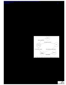
standard WSN nodes, which may allocate at most 1 KB of RAM to the entire network stack. Thus, we feel that sensor networks present the strongest case yet made for cross-layer design of the network protocol stack. Current implementations of network stacks in sensor networks follow a more traditional independent layering approach [6, 7]. The alternative architecture of a cross-layer network protocol stack is shown in Figure 1. We observe that there are N C2 pairwise combinations, including both the traditional neighbor-layer interactions of an independently layered network stack (arrows down the center) as well as “bonus” pairwise interactions between non-neighboring layers (arrows on either side of the stack). These bonus interactions represent opportunities for the cross-layer approach to improve performance over the traditional independently layered network stack. Also, though not shown, data structures and buffers can be shared across many layers, reducing memory consumption.
hardware and software. We choose a select subset of pairwise interactions, and validate that this subset achieves superior joint performance when compared to a more traditional independently layered stack, as measured in network throughput, latency, and energy lifetime. The challenges that we have overcome to accomplish this research include implementing each of the layers of our network protocol stack in both their independently layered forms and their crosslayered variants, selecting the specific cross-layer interactions to study, and designing and executing the experiments to evaluate these differing approaches in a testbed environment. In the following, Section 2 summarizes the related work in cross-layer design. Section 3 describes the design and implementation of the X-Layer cross-layer network stack. Section 4 explains the evaluation of X-Layer and the experimental results, including several observations that lead to a comprehensive new architecture for realizing cross-layer network stacks. Section 6 describes the rich future work left to be explored in this promising WSN research area. Section 7 concludes the paper.
2
Related Work
We classify prior work in cross-layer network research into three categories, namely research into cross-layer WSNs, mobile ad hoc networks (MANETs), and wired TCP/IP networks.
2.1
Figure 1. X-Layer’s cross-layer network protocol stack. The figure raises several intriguing broader research questions. Which sets of pairwise cross-layer interactions yield the greatest performance improvement in the network? More specifically, what data variables and structures at what layers are most pivotal to achieving improved performance? Given the possibility of feedback loops, what can be done to mitigate instability? How can such a cross-layer network stack be most efficiently and effectively realized? All of these research questions certainly deserve the WSN research community’s attention. However, the first and likely most important research question, which is answered by this paper, is whether we can show in a real world system that there is any measurable benefit at all to network performance due to cross-layer interactions, i.e. can we find at least one subset of pairwise cross-layer interactions that demonstrably improves the network? Our research community requires an empirical proof as to the efficacy of cross-layer approaches. The main contribution of this paper is that it quantifies the real-world benefits of cross-layer design by building a complete cross-layer network stack solution on standard WSN
Wireless Sensor Networks
Almost all prior work regarding cross-layer networking for WSNs has involved algorithmic analysis and/or simulation work, rather than building and evaluating an implementation of a cross-layer network stack. Since energy is a limited resource on wireless sensor nodes, much of the prior work has focused on energy conservation. [8] reviews approaches for optimizing at each layer of the WSN network stack and discusses motivations for cross-layer design, but does not provide a formal analysis of results. The main focus in this paper is on theory and design. [9] presents a cross-layer stack for WSNs that uses interaction between the MAC protocol and the routing protocol to minimize energy consumption; the primary focus here is on theory and simulation work. van Hoesel et. al. compare their crosslayer approach to traditional SMAC and DSR protocols, and show using simulation results that their cross-layer protocols achieve longer network lifetime. In a paper focused on simulation results, Sichitiu [10] describes a cross-layer interaction between the routing and MAC layers to conserve energy by setting up a synchronized off-on schedule for the wireless sensor nodes in a WSN. Simulation results verify that this energy conservation scheme can significantly increase network lifetime for certain types of networks. With a basis in theory and simulation, [11] proposes two energy efficient schemes for wireless ad-hoc and sensor networks that uses cross-layer interactions between the routing layer and MAC layer. In the first scheme, called Energy-Constrained Path Selection (ECPS), interactions between the MAC and routing layers are used to choose a route that maximizes the probability that the packet will reach the destination in at most some number of n transmissions. The second scheme,
called Energy-Efficient Load Assignment (E2LA), uses interactions between the MAC and routing layers to efficiently distribute load among a set of routes according to successful packet transmission probability. The successful packet transmission probability used in this paper is similar to the Expected Number of Transmissions (ETX) metric used in our routing layer. In [12], an algorithm for a cross-layer joint optimization problem is presented that seeks to maximize WSN lifetime. Joint optimal design of the physical, MAC, and routing layers is considered in this algorithm, and the authors perform numerical studies to show the benefits of their approach. [13] uses numerical analysis to survey energy consumption in WSNs using cross-layer models that jointly consider topology, the MAC layer, and radio transceiver energy consumption. The authors reach several interesting conclusions. One such conclusion is that with a realistic radio model and certain network conditions, single-hop communication can be more energy efficient than multi-hop communication. Both [12] and [13] focus primarily on theory and numerical studies and analysis. Cross-layer interactions in network stacks for WSNs impact the architecture and design of such stacks. Although Chameleon [6] is not a cross-layer network stack, the Chameleon architecture for sensor networks uses cross-layer bit-packed header fields to reduce the size of packet headers and conserve memory. Chameleon also implements crosslayer information sharing. SP [14] is also not a cross-layer network stack, but it does enable some cooperation between the network and link layers by implementing a shared neighbor table and message pool.
2.2
Mobile Ad-hoc Wireless Networks
There has also been much research into cross-layer networking for Mobile Ad hoc Wireless Networks (MANETs), since it is believed that a strictly layered approach inhibits the performance optimizations needed to deal with the dynamic mobile and energy-constrained environments [15, 16]. Most of this work involves theoretical and/or simulationbased work, rather than evaluation of a cross-layer network stack implementation for MANETs. [15] proposes the MobileMan architecture for MANETs, which allows different layers to cooperate by sharing network status information. No evaluation of results is presented in this paper. [16] makes the case for the importance of cross-layer design in ad hoc wireless networks and reviews opportunities for beneficial cross-layer interactions between different layers in the network stack. Both [15] and [16] focus on theory and design and do not present simulation or implementation results. In [17], Kawadia and Kumar present simulation results for several cross-layer interactions in a wireless ad hoc network. Their simulation results for examples involving an adaptive rate MAC protocol and adaptation of transmit power show that some cross-layer interactions can lead to unstable loops and an unintended negative impact on system performance. In [18] the authors discuss simulation results for a wireless ad hoc network that show improved application performance resulting from cross-layer interactions between the physical, data link, and network layers. While all of the papers mentioned so far in this MANET
subsection focus on theory, design, and/or simulation, [19] describes an actual implementation of a cross-layer interface for interaction between layers, called Xian. Xian is intended to facilitate cross-layer experiments on MANET testbeds, and is implemented as a set of Linux kernel space and user space components. Xian enables interaction between adjacent and non-adjacent layers. In the examples discussed in this paper, upper layers are able to access metrics provided by the 802.11 MAC layer. While the architecture of this system is interesting, clearly this particular implementation is not appropriate for resource-constrained wireless sensor nodes.
2.3
Wired Internet
Since it can be argued that the success of the wired Internet is primarily due to its layered architecture [17], the case for cross-layer networking in wired networks is less clear than it is for wireless networks. However, the authors of [20] contend that cross-layer associations are critical to network management tasks in the wired Internet, such as backbone planning, maintenance, and failure diagnosis. A crosslayer policy server and cross-layer database are proposed that would store the cross-layer associations between layers and enable the use of management applications that would exploit this information. In this paper, the authors focus on a discussion of the architecture of this cross-layer service.
3
Cross-Layer Network Stack Design & Architecture
This section discusses how we achieved X-Layer’s crosslayer network stack according to the model outlined in Figure 1. We discuss the pertinent protocols that were implemented at each layer, as well as the key variables that were exposed to cross-layer adaptation. Base case protocols were developed for each relevant layer conforming to an independently layered design, while their cross-layer cousins were developed in parallel by modifying the base cases to allow for cross-layer adaptation to other layers’ parameters. The choice of each protocol was directed by experience in sensor network design. For instance, the routing layer is a “tree” protocol which is a natural protocol for many sensor network applications. Many sensor network applications require data from many nodes to be routed to a “root node” or “sink node”. The nature of networks in which many nodes within a network are spread throughout a system of interest and one node is connected to a storage system lends itself to tree routing protocols. The MAC protocol is partially integrated into the Chipcon CC2420 radio, which provides link layer ACKs (important for reliability of sensor data) while using relatively low power to operate the radio (compared to 802.11 or bluetooth wireless systems). Frugal power usage is a key to making low cost sensor systems last in the field as long as possible. Also, since low power is important the transport layer tries to achieve reliability without using too much power or being too complex. Our cross-layer network stack is implemented using standard WSN hardware, namely TELOSB motes [21], and standard sensor OS software.
3.1
MAC & Physical Layer
The physical layer and its medium access control (MAC) layer present us with an interesting set of possibilities for cross-layer design. These optimizations or shared variables center around trading performance for power, or vice versa. Performance can be degraded, both in terms of radio power (wireless range) and MAC layer transmit/retransmit rates, in order to use less power and fewer bandwidth resources. The possibility for cross-layer integration of the MAC layer depends on the particular protocol being used. However, many MAC layer protocols support some form of beacons and/or retransmits (auto-acknowledgements). For this cross-layer design both were supported and the routing layer took advantage of the “link-level” auto-acknowledgements built into the ChipCon CC2420 radio. It is important to note that in this case the physical and MAC layers have already been partially interwoven due to the use of a radio that includes some MAC layer functionality. Adjusting radio transmit power is a possibility whenever the particular radio and driver software supports an interface for setting radio transmit power. In our specific implementation the ChipCon CC2420 radio was used and allowed us to modify radio transmit power. This functionality was integrated into the design of the routing layer. Other possibilities for cross-layer integration of the MAC layer could include modifying the maximum number and rate of MAC layer retransmissions, and using the link quality metrics (RSSI or LQI) directly (in this case the routing layer uses these metrics for another metric ETX).
3.2
Network Routing Layer
The protocol built for X-Layer’s routing layer is the Bidirectional Tree Protocol (BTP), a close relation to the Collection Tree Protocol [22] (CTP). BTP extends CTP to support bidirectional unicast routing, i.e. routing in both upstream and downstream data directions. The original CTP design forms a routing tree centered with a base station as the root or data sink. Unicast messages are routed towards the root by the tree’s leaf and branch nodes. As a basic tree protocol, CTP is based around a distance measure, specifically the distance or depth from a root. This distance measure is used to guide packet routing toward the root node. Such tree protocols are especially well suited for “data-centric” applications common to WSNs. BTP leverages this tree network topology to perform unicast routing in the reverse or downstream direction, i.e. from base station to a leaf sensor node. BTP, like CTP, is best used for relatively low traffic rates. It is best effort, meaning that it does not guarantee 100% delivery (this makes it a good protocol to use with the transport layer). Also, BTP makes the assumption that it can in some way infer the link quality of neighboring nodes in the network (those nodes that are only one hop away). This link quality is used to order the tree and make routing decisions. BTP assumes that nodes use link-level retransmissions (which is true of the 802.15.4 MAC layer in this case). The most important value or variable that guides the organizing and routing within BTP is called ETX [23], the estimated number of transmissions necessary to get to the root or to get to certain other destination nodes in the network. ETX
if (meanNextHopETX > ETX_HIGH_THRESHOLD && CURR_TRANSMIT_POWER < MAX_TRANSMIT_POWER) { increaseCurrTransmitPower(); } else if (meanNextHopETX < ETX_LOW_THRESHOLD && CURR_TRANSMIT_POWER > MIN_TRANSMIT_POWER) { decreaseCurrTransmitPower(); }
Figure 2. BTP Transmit Power Adjustment Pseudocode is cumulative and therefore implies the total number of transmissions that will be made on all hops along the path taken from origin to destination. ETX is used by BTP as a “routing gradient” meaning that packets will follow a path of least ETX. In our BTP implementation, we obtained the CC2420 radio’s link quality indicator (LQI), rather than RSSI, as an estimator of the link quality [24]. We defined ETX as a sum of all LQI values from each hop from a source node to a destination node. A weighted moving average algorithm is used to smooth changes to LQI over time. In our implementation, LQI is scaled such that LQI is inversely proportional to link quality. That is, large LQI values indicate poor link quality, while small LQI values indicate good link quality. BTP is an example of how different routing protocols provide unique aspects of design to other layers, depending on the indicators or metrics used by the protocol. In the case of BTP, ETX is the parameter that is exposed to other layers as an indicator. The method by which we exposed ETX was to create a special API function that could be called to read ETX by any layer. The ETX value is used by other layers to infer connectivity over the implied topology. Therefore, it is used to modify the radio transmission power, which in turn can result in a different topology that often leads to better connectivity (it did in all our tests, and is rather intuitive). The routing layer provides us with an interesting chance to integrate cross-layer design with multiple layers both above and below. In X-Layer, the routing layer provides metrics for the application and transport layer while incorporating variables from the physical layer into its design. The cross-layer behavior implemented for BTP involves an interaction with the physical layer. BTP adjusts radio transmit power for each wireless sensor node in the network based on the ETX value for the next hop in the route toward the destination node. A weighted moving average algorithm is used to smooth changes to next-hop ETX over time. If the smoothed next-hop ETX value exceeds a fixed threshold value, then we increase transmit power. Since high ETX values indicate poor link quality, the goal here is to improve link quality by increasing transmit power. If the smoothed nexthop ETX value is below a minimum fixed threshold value, then we decrease transmit power. Since low ETX values indicate good link quality, the objective of this logic is to reduce transmit power and thus reduce energy consumption while still maintaining good link quality. Figure 2 shows a representation of this logic in pseudocode. By running this transmit power adjustment logic in a distributed fashion on all sensor nodes in the network, we seek to find a near-optimal logical network topology and route between the source and destination nodes.
currETX = (ALPHA * newETX) + (1 – ALPHA) * averageOfPreviousFiveETXs; ETXdiff = newETX – currETX; if (ETXdiff > 0) increaseSendRate; else if (ETXdiff == 0) doNothing; else if (ETXdiff < 0) decreaseSendRate;
Figure 3. Application Send Rate Adjustment Pseudocode
3.3
Transport Layer
X-Layer implements a simple stop-and-wait reliable transport protocol that provides support for multiple concurrent connections between two nodes in the network, called the Lightweight Transport Protocol (LTP). Stop-and-wait was chosen instead of a windowing scheme to reduce memory usage and code size, which are of particular concern on resource constrained wireless sensor nodes. End-to-end ACKs are used to ensure reliable data transfer between the sending and receiving nodes. We use a timeout mechanism based on the Jacobson-Karels algorithm for the base protocol. The cross-layer behavior implemented for the transport protocol involves an interaction with the routing layer. This cross-layer behavior makes use of ETX information provided by the routing layer (BTP) to set the timeout in the transport layer. Since ETX is cumulative in BTP, we use the ETX from the source to the destination node to estimate the number of hops between the source and destination by dividing ETX to the destination by an ETX per hop value. numHopsestimated =
ET Xcumulative ET X per hop
Based on experimental data, we have observed that an ETX value of approximately 12 indicates good link quality over one hop for our system, and is thus used as the ETX per hop value. Logic in LTP tracks changes in the estimated number of hops from the source to the destination over time. If the change in estimated number of hops over time exceeds some HOP COUNT DELTA threshold, then we use the estimated number of hops to set the timeout value in LTP. Based on observations of our system, we have found that 1000 ms is a reasonable value for timeout over one hop. Therefore, to set the timeout value, we simply multiply the estimated hop count by the timeout value per hop (1000 ms). timeoutend−to−end = numHopsestimated ∗ timeout per
hop
By using ETX to the destination to set timeout, we are able to adapt more quickly to dramatic changes in connectivity between the source and destination nodes than would be possible with Jacobson-Karels.
3.4
Application Layer
We designed a basic sensing application that produced sensor data at a fixed rate of one packet every five seconds. This data application was not adaptive to changes in network topology or link quality. This is typical of many deployments of sensor applications [25, 26].
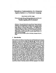
Figure 4. Summary of specific cross-layer interactions implemented in X-Layer.
To explore the effect of cross-layer interactions, we modified this application to adjust its packet sending rate in response to changes in network quality. In particular, we explored the cross-layer interaction between the application layer and the routing layer. The application receives link quality information from the routing layer and uses that information as an input to improve the overall throughput as well as reduce current draw. Our sample application received the ETX values for each packet from the routing layer, performed a weighted averaging algorithm with the previous values, compared the smoothed result with the current ETX average, and adjusted the packet send rate based on the comparison. If the new ETX average is better than the current ETX average, the node takes advantage of the good link quality and sends packets at a higher rate. On the other hand, if the new ETX average is worse than the current ETX average, the node assumes the link quality has dropped and sends packets at a lower rate. Figure 3 represents the pseudocode for this logic. The ALPHA parameter could be used to adjust the weights of the averaging algorithm so that the ETX value does not fluctuate as much when the wireless link is unstable. How much the rate is adjusted varies from environment to environment.
3.5
Summary of Cross-Layer Interactions in X-Layer
Figure 4 summarizes the pairwise cross-layer interactions that were implemented in X-Layer. BTP calculates ETX values and exposes them to both the transport and application layers, which adjust timeouts and sending rates respectively. BTP queries the physical layer to receive LQI information and also adjusts transmit power dynamically.
Figure 5. Testbed Programming and Data Collection Software
4
Cross-Layer Evaluation
This section explains the methodology and hardware used to evaluate our X-Layer network protocol stack. It discusses the experimental setup and comparison cases. The results from the experiments are presented in the second part of this section. Finally, we present observations that lead to a new cross-layer architecture which we feel more fully realizes the potential of cross-layer networking in wireless environments. This solution addresses how a cross-layer network stack may be designed in an orderly abstract manner while managing shared resources in an efficient and organized way.
4.1
We also conducted another comparison between two different network stacks running beneath application code that attempts to extend battery life through reducing the application layer send rate as battery voltage drops. The performance of differently configured network stacks are compared to each other in order to understand how optimizations in one layer (the application layer) may be affected by configurations within other layers (the routing and transport layers). The methodology for this test was to run the same energy-aware adaptive application on top of the basecase.2 stack and also the basecase.10 stack. These network stacks were chosen for the differing topologies they provided, a good example of how small changes in network stack configuration affect the performance of other layers. For analysis, we focused on three metrics: goodput (both in absolute terms and as a success ratio of packets sent from the application layer), total throughput (total amount of bandwidth put in the air by the network), and latency (endto-end time for application layer to send and receive). “goodput” will give a sense of how much data is actually being sent through the network successfully and when compared to total throughput one can see how efficient the particular network stack was at achieving that “goodput”. The latency is particularly important for understanding how the changes to transport layer timeouts and resends affects the overall endto-end network latency. Receive Ratio
Experimental Methodology
We evaluated the performance of our X-Layer cross-layer network protocol stack and compared it to an independently layered network protocol stack. This comparison was performed over an indoor testbed of 56 TELOSB motes. The testbed was set up to allow download of program images via USB cables attached to each mote. We developed the software to manage the testbed for our experiments. Figure 5 shows a screen shot of the testbed collection software’s programming and data collection environment, in which the ELF files corresponding to our network stacks were loaded along with an end-to-end communication application onto the sensor nodes in the testbed. Depending on the power level, the network topology varies from an all-to-all network, in which every node has a one hop connection to every other node, to a multi-hop network sometimes four hops across. Diagnostic output was collected via the wired USB infrastructure while the network stacks executed and forwarded wireless data. We evaluate three different non cross-layer “basecases” for comparison to our cross-layer stack. The basecase code runs the same protocols at each layer as our cross-layer design: LTP transport, BTP routing, and the same application code. The three basecases are configured to different radio power levels corresponding to different network topologies. The power levels given to the CC2420 radio interface are 2, 10, and 30 (about dBm -2.87E+05, -1.10E+05, and -9.14E+02 respectively). We will refer to these three cases as basecase.2, basecase.10, and basecase.30. We compare these three cases to the X-Layer cross-layer network stack implementation.
100.00% 90.00% 80.00% 70.00% 60.00% 50.00% 40.00% 30.00% 20.00% 10.00% 0.00% X-Layer
Basecase.2
Basecase.10
Basecase.30
Figure 6. End-to-End Receive Ratio
4.2
Experimental Results
The first metric presented is that of end-to-end receive ratio. This part of the evaluation is meant to show what overall performance the compared cases achieve. These results should be kept in mind when evaluating the other performance metrics. In Figure 6, we show the percentage of packets that are successfully transported end-to-end from source node to the sink, or root node of the tree. The experiments demonstrated that given reasonable connectivity within BTP, the transport layer ensured 100% packet delivery throughout the length of the experiment Page for1 both X-Layer and most variants of the discretely layered stack. However, in basecase.2, in which the transmit power is held at a constant setting of 2, the connectivity was intermittent and resulted in
Average Resends Per Packet
Min Avg Max Power
3
30
Min-Avg-Max
29 2.5
28 27
2
26 1.5
(mA)
25 24
1
23 22
0.5 21 20
0 X-Layer
Basecase.2
Basecase.10
X-Layer
Basecase.30
Figure 7. Resends Per Packet Sent a very low receive ratio. However, poor connectivity was not only due directly to low radio transmission power, but as will be shown later in the discussion of Figure 7, the poor connectivity resulted in a greater number of retransmissions (more wireless traffic) and likely caused interference. When running protocols that retransmit or resend failed packets, poor connectivity can leads to more transmissions and more inter-node interference, further degrading end-to-end network connectivity. This interference is evaluatedPage through measuring the to1 tal number of resends per packet so as to understand the amount of bandwidth actually being sent by the network in order to achieve the end-to-end success rates from Figure 6. Figure 7 shows for each test case the average number of resends per packet, which is inversely proportional to goodput. Specifically this metric refers to the average number of extra transmissions (optimally, all packets would need only be transmitted once by the sender). The best performer in this case was the non-cross-layer stack set to a constant transmission power of 30. This is not unexpected due to the fact that this power level results in an all-to-all network topology with very good connectivity. However, this is achieved at the cost of much higher energy usage by the radio. The crosslayer stack, results in a slightly higher number of resends than basecase.30, however it is still much more efficient than both basecase.10 and basecase.2. While basecase.10 had sufficient inter-node connectivity to successfully transport all packets across the network it resent packets more than 8 times as often as basecase.30. As stated earlier, the high number of retransmissions in basecase.2 further degraded the already poor inter-node connectivity. The performance of the cross-layer stack in terms of retransmissions is rather impressive considering that the crosslayer network code resulted in a changing topology, optimizing radio transmission power for multi-hop or single-hop topologies depending on inter-node connectivity. In spite of the changing topology the cross-layer stack was able to fix routes by modifying transmission power quickly using information from the MAC and routing layer. This information was concurrently taken into account at the transport
Figure 8. (mA)
Basecase.2
Basecase.10
Basecase.30
Minimum/Average/Maximum Power Usage
layer, which could then modify its connection timeout so as to avoid unnecessarily resending the packet. This is an example of how sharing of information between the layers made all layers more resilient to sudden changes within each other. While three of the cases (basecase.10, basecase.30, and X-Layer) achieved 100% end-to-end receive ratios (Figure 6) the costs in terms of total transmissions (or traffic created) were not the same. Neither was the amount of power the different cases required to achieve the same end goal, as Page 1 presented in Figure 8. The average power in terms of current consumption was measured every 10 seconds while the experiment was running. The minimum, mean (average), and maximum of these power usage values are shown for each case in Figure 8. While basecase.30 achieved the best connectivity and transmission efficiency due to higher radio transmission power, it was precisely the high transmission power that caused this code to use more overall power than both the cross-layer code and basecase.10. Even though basecase.10 ended up resending packets more than 8 times as often as basecase.30, it still used less power on average to achieve the same goal of 100% end-to-end packet transport. It should be noted that because basecase.10 made many retransmissions, continuing to increase the application layer send rate may have resulted in basecase.10 retransmissions causing enough interference so as to cause the network to break down, while basecase.30 may have continued to support a higher application layer data rate. However, for many sensor network applications a send rate of 1 packet every five seconds is more than enough [27, 28]. The basecase.2 experiment showed how detrimental it can be to have radio transmission configured too low. If the transport or routing layers are retransmitting packets too often due to bad connectivity, then much more power can end up being consumed as presented in the relatively higher average power usage of basecase.2. This is a classic case of how locally designing or optimizing certain layers can affect other layers in a very negative, and often perplexing (or contradictory) fashion. In this case, lowering the physical layer transmission power, perhaps to save power, resulted in the opposite
Average Latency
Application Layer Send Rate Adaptation
600
26.5 26
500
25
(mA)
milliseconds
25.5 400
300
24.5 24
200
23.5
Basecase.2 Basecase.10
100 23 >2.98
0 X-Layer
Basecase.2
Basecase.10
Figure 9. Average End-to-End Latency
effect, consuming more power overall due to transport and routing layers creating extra traffic to compensate for poor link connectivity. In the end, the overall system used much more power than the same code with the radio transmission power turned up (and failed to achieve reliable transport). The cross-layer stack uses less power on average than the other cases. This is due to X-Layer implementing the transport and routing layers to react to changes in other layers. High connectivity was achieved Page while keeping transmission 1 power low. The optimization of competing factors (power usage and connectivity) was not explicitly written into the cross-layer design. Rather, each layer was designed to react to information from other layers in a reasonable pairwise fashion. When connectivity is bad on a packet arriving at physical layer, the routing layer would immediately react by changing the routing tables to reflect this fact, changing the ETX value. Also, the transport layer may adjust its timeout value. All these changes allowed for connectivity to be established while keeping power low and avoiding many unnecessary retransmissions. Due to the cross-layer design, reliable transport was achieved efficiently (few transmissions) using the lowest average power usage. The final metric evaluated in Figure 9 is that of end-toend latency, namely how long it took a successfully relayed packet to travel from the source node to the root. This metric is most reflective of the topology of the network. In basecase.10 and basecase.30 there was always a direct link (of varying quality) being used by the routing layer, hence the latency is reflective of how long it took on average to send, receive, and acknowledge a single transmission. In the basecase.2 experiment it usually took 3 or 4 hops for packets to reach the root from the source and this is reflected in higher average end-to-end latency representing many transmissions within the network. In the cross-layer experiment the topology favored a direct connection (when good quality) between the source node and the base. However, sometimes transmission power was reduced and a multi-hop network used. This changing topology is reflected in the slightly higher average end-to-end latency of the cross-layer experiment.
2.76
Z && |M[i]-M[i-1]|==12 || U*V