Experimental Implementation of an Algorithm for Cooperative Searching of Target Sites David J. Tung1 , Bao Q. Nguyen2 , Yao-Li Chuang3 , Chung H. Hsieh2 , Zhipu Jin4 , Ling Shi5 , Daniel Marthaler3 , Andrea L. Bertozzi3 , Richard M. Murray5 Abstract— This paper discusses a greedy decentralized cooperative search algorithm and its implementation and results on the Caltech Multi-Vehicle Wireless Testbed (MVWT). The algorithm uses inter-vehicle communication as a performance accelerator and is robust against vehicle loss. Testbed vehicles search a list of spatial targets. Two different types of vehicles are used for this experiment: the Steelebot, a first order control vehicle that drives itself with wheels, and the Kelly, a second order control vehicle that propels itself with fans.
I. I NTRODUCTION Cooperative searching by autonomous vehicles through a field of potential target sites has a wide range of applications from military scouting to automated trash collection [1]. The problem considered here is motivated by mine countermeasures (MCM), involving locating, visiting, and identifying mines from a list of possible target sites. Because this task can be very hazardous, it is quite appropriate for the use of autonomous vehicles. The problem of cooperative target searching has been discussed theoretically in many recent papers, e.g. [2], [4], [6], [8], [14], [15]. Topics include path planning, task allocation, and target assignment. The current work involves implementing the Fractional Bandwidth approach from [4] on the Caltech MVWT testbed. There are several highlycoupled layers involved in this implementation that include network architecture, software structure, vehicle dynamics, and point to point control. The Fractional Bandwidth approach [4] to the MCM problem is a decentralized algorithm for a group of vehicles to go to a set of possible target locations. Each vehicle is capable of accomplishing the entire mission, which makes this approach robust against vehicle loss and communication failure. Inter-vehicle communication prevents them from going to the same target sites, making communication a performance accelerator. The Fractional Bandwidth approach is implemented using a greedy search algorithm [4]. In this algorithm, each vehicle keeps track of targets as available, selected, or 1 Dept.
of Computer Science, UCLA, Los Angeles, CA 90095
[email protected] 2 Dept.
of Electrical Engineering, UCLA, Los Angeles, CA 90095
[email protected], chung
[email protected] 3 Dept. of Mathematics, UCLA, Los Angeles, CA 90095 {chuang, daniel, bertozzi}@math.ucla.edu 4 Dept. of Electrical Engineering, California Institute of Technology, Pasadena, CA 91125
[email protected] 5 Control and Dynamical Systems, California Institute of Technology, Pasadena, CA 91125 {shiling,
murray}@cds.caltech.edu
done, with all targets being initially available. Each vehicle also keeps track of its next target, which its current target destination. In field applications such as underwater searching, the vehicles have a limited communication range, thus we explore the algorithm performance with both fixed and unlimited communication range. II. A LGORITHM A. Description The following is a description of one iteration of the greedy search algorithm loop. This loop is continued until all targets are marked as done. Each vehicle selects the nearest available target as its next target. If there are no available targets, a vehicle selects the nearest selected target as its next target. The vehicles then communicate their position information and next target selection with other vehicles within communication range. If they share the same next target selection, the vehicle that is farther away from the target marks this target as selected so that it would be able to select another available target. If they do not share the same next target selection, in the case that the received next target selection is available, it is upgraded to selected. Vehicles within communication range share their done target lists and accordingly upgrade available and selected targets to done. Each vehicle travels to its next target selection target location. If a vehicle is within the search radius of the target, the vehicle marks the target as done. B. Structure The greedy algorithm is implemented using the following structure: Initialization: Each vehicle has the target locations and corresponding target flags of available, selected, and done. All targets are initially available. Each vehicle also has a next target variable for the target to which it travels. Program Loop: 1. Select closest target: Each vehicle selects the nearest available target. If no target is available, the vehicle selects the nearest selected target. The selected target index is stored as the next target. If no available and selected targets are left, the mission is successful and ends. 2. Communicate next target selection: Each vehicle finds the next target and position of every other vehicle within communication range. a) Arbitrate next target selection: If two vehicles share the same next target selection, the vehicle that is further
away marks this target as selected so that it would be able to select another target that is available at step 2 of the next iteration. b) Communicate next target selection: If two vehicles do not share the same next target selection and the current status of the received next target selection is available, it is upgraded to selected. 3. Communicate done target list: Each vehicle within communication range share their target lists for all targets they have as done. If the receiving vehicle’s target status is available or selected it is upgraded to done. 4. Travel to the next target selection target location: This is done for each vehicle using a point to point controller. 5. Mark located target as done: For each vehicle, if the vehicle is within the search radius of the target, it is marked off as done. 6. Return to step 2 until all targets are done. III. T ESTBED I MPLEMENTATION The greedy search algorithm is implemented on the Caltech Multi-Vehicle Wireless Testbed (MVWT) [3], a platform designed for experiments involving cooperative multi-vehicle control. The MVWT consists of vehicles that can communicate over a wireless network, an arena for the vehicles to run in, an overhead camera system called the Lab Positioning System (LPS), and an off board computer network. Each vehicle in the MVWT has an onboard computer, onboard sensors, and an 802.11b wireless Ethernet card [3]. The vehicles wear hats that the vision system uses to identify each vehicle, its position, and its orientation. The greedy search algorithm is implemented on two different types of vehicles, the Steelebots and the Kellys.
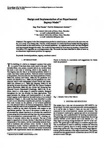
Fig. 1.
Steelebot picture (top). Kelly picture (bottom)
A. Steelebot Implementation The greedy algorithm is implemented on the Steelebots because their first order dynamics make them the easiest vehicle on which to implement a point to point controller. The algorithm is implemented using a centralized computer network and point to point controller that sends velocity commands to the Steelebots. Steelebot. The Steelebot, see Fig. 1 (top), was produced at the University of West England [9]. It has a two wheel differential drive system with an independent actuator for each wheel. This makes it useful for experiments that require a vehicle with the ability to make sharp turns and to brake. The Steelebot is based on two main systems. The first is a tiny Amporo PC that runs the Linux operating system. The second is a large motherboard that provides power for operation and communication among the various devices on the robot [11]. The Steelebot has an 802.11b wireless Ethernet card that it uses to communicate on the MVWT wireless network. Centralized Network Structure and Software. The Steelebot implementation of the greedy algorithm uses the MVWT Application Programmer Interface (API) [7] and its centralized computer network, shown in Fig. 2. The
Fig. 2. The MVWT API architecture [7], which is used in the Steelebot greedy algorithm implementation.
API was derived from the RoboFlag architecture [5] and developed for users to control robots on the MVWT testbed. RoboFlag is a robotic capture the flag game involving multiple vehicles and humans in the loop. The MVServer is a communication interface from RoboFlag between off board computers, the vision system, and robots in the field. The MVWT API was designed to allow users to develop application programs that interface with the MVServer. Programmers would write custom code that interfaces with the API functions, forming the Client. The MVWT API has been tested to work on computers running Windows XP, and the MVServer runs on Linux. In the Steelebot implementation of the greedy algorithm, the Client program receives position information for the vehicles in the field and stores the target status lists and next target selection for each vehicle. The inter-vehicle communication is simulated in the Client by storing and communicating the target information for each vehicle in the field. The Client is also used to limit the communication range between vehicles. The experiments are carried out using either one or two Steelebots, and easily scale to multiple robots. Point to Point Controller. The MVWT API provides the point to point controller used on the Steelebots [7]. The controller calculates the x-position error and the y-position error, which are the coordinate differences between the vehicle’s current position and target position, respectively. It sets the x-velocity and y-velocity commands proportional to the x-position error and y-position error. These velocity commands are sent to the Steelebots, which run a controller from RoboFlag that translate these velocity commands into a magnitude and direction. B. Kelly Implementation The greedy algorithm is implemented on the Kellys because their second order dynamics are closer to a typical underwater vehicle used for MCM applications. This implementation uses a decentralized computer network where the processing is done onboard each Kelly. Kelly. The Kelly, see Fig. 1 (bottom), slides on three omni-directional casters and is driven by two ducted fans. Its processing is done by an onboard 700 MHz laptop computer that runs QNX, a real time operating system. Kellys can communicate with each other and with a central command computer via the Local Wireless Network [10]. The Kelly is a second order dynamic vehicle whose x, y coordinate positions and orientation θ are described by the following equations of motion [3], [10]: m¨ x = −µx˙ + (FR + FL ) cos(θ),
(1)
m¨ y = −µy˙ + (FR + FL ) sin(θ),
(2)
J θ¨ = −ψ θ˙ + (FR − FL )rf .
(3)
In the above, FR and FL are the right and left fan forces, respectively. The fans are separated by the length 2rf . The mass is m and mass moment of inertia is J. The linear
Fig. 3.
An overhead representation of the MVWT vehicle Kelly [3].
Fig. 4. The computer network architecture of the Kelly greedy algorithm implementation.
viscous friction coefficient and rotational viscous friction coefficient are µ and ψ, respectively. See Fig. 3 for an overhead representation of the Kelly showing x, y, θ, FR , FL , and rf . Decentralized Network Structure and Software. The greedy algorithm implementation on the Kellys uses a decentralized computer network, as shown in Fig. 4. This decentralized network architecture with onboard processing and peer to peer communication is true to the intended field applications. The Kellys are connected to the vision computer system and to each other via the Local Wireless Network. They each receive their own position information from the Lab Positioning System. Each Kelly periodically communicates its position information, target list containing the status of each target, and next target selection. The position information is communicated to limit the communication range between Kellys. If the communication range is limited, the target list and next target information received from another vehicle is ignored unless it is within communication range. Point to Point Controller. The point to point controller on each Kelly is implemented using the Virtual Attractive Repulsive Potential control method [13]. A virtual attractive potential is located at the target site and removed once the vehicle reaches that point. The virtual potential attracts the vehicle according to the force law [12]: m
h i k~ z −~ z0 k d2 ~z dw ~ = m 2 = αξ~ − β w ~ − ∇~z −Ca e− la , dt dt
(4)
Fig. 5. One vehicle, three targets. The x’s represent the target locations, the circle represents the vehicle starting point, the dotted line shows the simulation vehicle path, and the solid line shows the live run vehicle path. The axes are labeled in meters.
where ~z, w ~ represent the position and velocity of the vehicle; ξ~ is the unit vector in the direction of w, ~ ~z0 represents the position of the target; α is a self-propulsion force in the direction the vehicle is headed; β is the friction coefficient; Ca defines the strength of the attractive potential, which decays exponentially according to the characteristic lengths la . Refer to [13] for a discussion of how equation (4) maps onto equations (1-3) in order to directly set the fan speeds. IV. E XPERIMENTATION R ESULTS A. Steelebots Experiments are conducted using the Steelebots to verify that the algorithm is producing expected results. Each experiment is first run on a numerical simulation, and then its results are compared with those from the testbed using the Steelebots. One Vehicle, Three Targets. Fig. 5: The vehicle consistently travels to the next closest available target in both the simulation and in the testbed implementation and ends its mission when all three targets are found. Notice that in the live run, the vehicle goes through the first and second targets, and not the third target. This is because the live run uses a threshold distance of 0.2 m between the target and the vehicle to consider a target done, while the simulation uses only 0.02 m for this threshold. Two Vehicles, Two Targets, Unlimited Communication Range. Fig. 6 (top): With unlimited communication range, the vehicles go to their nearest available target. Once they get to their targets, they communicate their target lists and stop moving since all the targets are found. Fig. 6 (bottom): Even though both vehicles are initially closer to the same target, they successfully arbitrate their next target selection with unlimited communication range. The one closer to this target goes to it while the other vehicle immediately goes to the other target. As in the single vehicle case, the vehicle paths from the live runs do not fully cover the targets because the experimental threshold
Fig. 6. Two vehicles, two targets, unlimited communication range. The x’s represent the target locations, the circles represent the vehicle starting points, the dotted lines show the simulation vehicle paths, and the solid lines show the live run vehicle paths. The axes are labeled in meters.
distance of 0.2 m is larger than the simulation threshold distance of 0.02 m. Two Vehicles, Two Targets, Limited Communication Range. Fig. 7 (top): With communication range limited to one meter, each vehicle travels to its nearest available target, and then moves towards the other target. They move within communication range, share target lists, and complete the mission. Fig. 7 (bottom): Communication range is limited to one meter. Both robots start off traveling to their nearest target locations, and they arbitrate their next target selections once they are within communication range. When this happens, the vehicle that is further away begins moving towards the other target. As in previous runs, the live run has a larger threshold distance than the experimental run. Two Vehicles, Three Targets, Limited Communication Range. Fig. 8: With communication range limited to one meter, the vehicles start off 0.75 m from each other. They go to their closest targets, while communicating their next target selection and target lists. As a result of their communication, they then travel toward the target at (0.5, -2.5) and finish when the first robot reaches this target. B. Kellys Experiments are conducted using the Kelly to test the algorithms with vehicles that have second order dynamics.
Fig. 9. Two Kellys performing the greedy search algorithm with four targets. The solid colored triangle and solid colored circle represent the vehicle current locations, and the solid lines that follow them are their paths. The radii of the circles around the vehicles represent half the distance over which the vehicles can communicate; thus the vehicles communicate when the circles intersect. The vehicle communication range is 1.5 m, so the circles have radii of 0.75 m. The squares with x’s in them represent the target locations. The axes are labeled in meters. Fig. 7. Two vehicles, two targets, limited communication range. The x’s represent the target locations, the circles represent the vehicle starting points, the dotted lines show the simulation vehicle paths, and the solid lines show the live run vehicle paths. The axes are labeled in meters.
Fig. 8. Two vehicles, three targets, limited communication range. The x’s represent the target locations, the circles represent the vehicle starting points, the dotted lines show the simulation vehicle paths, and the solid lines show the live run vehicle paths. The axes are labeled in meters.
Two Vehicles, Four Targets, Limited Communication Range. Two Kellys are used to search four targets. Communication range is limited to 1.5 m. The run is shown in Fig. 9. The starting positions of the Kellys put them out of communication range and they start moving toward the same target. The Kellys then move into communication range and arbitrate their next target selection (Fig. 9a). The one that is further away selects a different target. After the next target arbitration, the Kellys attempt to locate their selected targets (Fig. 9b). Having located their first targets, the Kellys select new targets and move towards them (Fig. 9c). When one of the Kellys locates the last remaining target, the other Kelly has moved within communication range and they communicate their target lists (Fig. 9d). At this point, the vehicles have accounted for all the targets, and they stop moving since their mission is complete. Note that the second order dynamics give the Kellys’ trajectories considerable amounts of oscillation. As a result, the live runs with the Kellys use a threshold distance of 0.3 m between the target and the vehicle to consider a target done. Two Vehicles, Four Targets, Unlimited Communication Range. Two Kellys are used to search four targets. Communication range is unlimited. The following is a description of the run at each point in time shown in Fig. 10. Fig. 10a (27 seconds): The Kellys are traveling to the
the vehicle to consider a target done. Fig. 10 shows the algorithm’s robustness against vehicle failure. The live run data showing the greedy search algorithm working well on the Kellys is particularly significant as it indicates the algorithm has promise for underwater or aerial vehicles that have second order dynamics. The greedy search algorithm is a simple and effective approach that is useful for developing the implementation framework for more sophisticated algorithms. Future work could involve the testbed implementation of different algorithms for task assignment and might also handle dynamic target generation as in [6]. VI. ACKNOWLEDGEMENTS This work was supported by ONR grant N000140410054, ARO grant DAAD19-02-1-0055, NSF grants ACI-0321917 and DMS- 9983726. R EFERENCES
Fig. 10. Two Kellys performing the greedy search algorithm with four targets. The solid colored triangle and solid colored circle represent the vehicle current locations, and the solid lines that follow them are their paths. The communication range is unlimited. The squares with x’s in them represent the target locations. The axes are labeled in meters.
same target. The one that is closer to the target begins oscillating and does not reach the target. Fig. 10b (32 seconds): The Kelly that was closer to the target at 27 seconds continues to oscillate and does not reach the target. The other Kelly moves towards this target, reaches it, and the mission is complete. This demonstrates the algorithm’s robustness against vehicle failure. V. C ONCLUSION The live run data from both the Steelebots and Kellys demonstrate the greedy search algorithm performing well in a physical environment. This validates the greedy search algorithm’s structure and effectiveness. It also demonstrates that the algorithm can be successfully adapted to different vehicle types, network architectures, and software structures. The fact that the simulation data and the data from the Steelebot runs match up very closely can be attributed to the accurate point to point control on vehicles with first order dynamics. The Kellys, with their second order dynamics, have less accurate point to point control than the Steelebots and thus require a larger threshold distance between the target and
[1] R. C. Arkin and T. Balch, Cooperative Multiagent Robotic Systems in Artificial Intelligence and Mobile Robots, D. Kortenkamp, R. P. Bonasso, and R. Murphy eds, MIT Press, 1998. [2] R. W. Beard, T. W. McLain, M. A. Goodrich, and E. P. Anderson, Coordintaed target assignment and intercept for unmanned air vehicles, IEEE Trans. Robotics and Automation, 18(6):911-992, 2002. [3] T. Chung, L. Cremean, W.B. Dunbar, Z. Jin, E. Klavins, D. Moore, A. Tiwari, D. van Gogh, and S. Waydo, A platform for cooperative and coordinated control of multiple vehicles: The Caltech Multi-Vehicle Wireless Testbed, Proc. of the 3rd Conference on Cooperative Control and Optimization, Dec. 2002. [4] B. Cook, D. Marthaler, C. Topaz, A. Bertozzi, and M. Kemp, Fractional Bandwidth Reacquisition Algorithms for VSW-MCM, Multirobot systems: from swarms to intelligent autonoma, Volume II, 2003, Kluwer Acad. Publishers, Dordecht, A.C. Schultz et. al. eds. 77-86. [5] R. D’Andrea and M. Babish, The RoboFlag Testbed, in Proc. American Control Conference, pp 656-666, 2003. [6] E. Frazzoli and F. Bullo, Decentralized Algorithms for Vehicle Routing in a Stochastic Time-Varying Environment, in Proc. IEEE Conference on Decision and Control, 2004. [7] J. Gibbs and D. Tung, Caltech MVWT API. http://www.math.ucla.edu/ bertozzi/MVWTproject/ [8] A. E. Gil, K. M. Passino, S. Ganapathy, and A. Sparks, Cooperative scheduling of tasks for networked and uninhabited autonomous vehicles, in Proc. IEEE Conf. on Decision and Control pp 522-527, Maui, Hawaii, December 2003. [9] Intelligent Autonomous Systems Laboratory (IAS), University of West England. www.ias.uwe.ac.uk [10] Z. Jin, Dynamics and Controllers of Vehicle Kelly, April 7, 2004, California Institute of Technology, Pasadena, CA, USA. [11] S. Kazadi, MooreBot User Manual, February 15, 2000, Pasadena, CA, USA. [12] H. Levine, W.-J. Rappel, and I. Cohen, Physical Review E., Vol. 63, 017101 (2000) [13] B. Q. Nguyen, Y.-L. Chuang, D. J. Tung, C. H. Hsieh, Z. Jin, L. Shi, D. Marthaler, A. L. Bertozzi, and R. M. Murray, Virtual Attractive Repulsive Potentials for Cooperative Control of Second Order Dynamic Vehicles on the Caltech MVWT, September 2004, submitted to 2005 ACC. [14] A. Richards, J. Bellingham, M. Tillerson, and J. How, Coordination and control of multimple UAVs, in Proc. AIAA Conf. on Guidance, Navigation, and Control, Monterey, CA, August 2002. [15] C. Schumacher, P. R. Chandler, S. J. Rasmussen, and D. Walker, Task allocation for wide area search munitions with variable path length, in Proc. American Control Conf., pp 3472-3477, Denver, CO, June 2003.