damage predicting methods is the realistic modeling of the impact loading. An im-
portant reference in the numerical modeling of bird strikes is Willbeck (1977), ...
Copyright © 2010 Tech Science Press
CMES, vol.70, no.2, pp.191-215, 2010
An Explicit Numerical Modeling of Soft Body Impact Damage in Metallic Airplane Structures I. Smojver1 , D. Ivancevic1 and D. Mihaljevic2
Abstract: This paper tackles the problem of numerical prediction of bird strike induced damage in real aeronautical structures using highly detailed finite element models and modern numerical approaches. Due to the complexity of today’s aeronautical structures, numerical damage prediction methods have to be able to take into account various failure and degradation models of different materials. The work presented in this paper is focused on damage modeling in metallic items of aeronautical structures. Abaqus/Explicit has been employed to perform geometrical and material nonlinear transient dynamic analyses. The problem of soft body impacts has been tackled by applying a hybrid Eulerian Lagrangian technique, thereby avoiding numerical difficulties associated with extensive mesh distortion. Eulerian modeling of the bird impactor resulted in a more realistic behavior of bird material during impact. The main focus of the work presented in this paper is the application of damage prediction procedure in damage assessment of bird impact on a typical large airliner slat structure and comparison with damage observed during exploitation of a real slat structure. Due to the high cost of gas-gun testing of aircraft components, experimental testing on the real flap structure could not have been performed. Validation of the hybrid formulation in solving bird strike problems has been achieved by comparison with available references. Keywords: bird strike, Coupled Eulerian Lagrangian formulation, structural impact, strain rate effects, damage, aeronautical structure. 1
Introduction
Collisions with birds are becoming a growing threat to flight safety due to changes in migration routes of flocking birds [Echenfelder (2005)] and ever increasing air traffic. The ability of critical aircraft structures to withstand foreign object impact 1 Faculty
of Mechanical Engineering and Naval Architecture, University of Zagreb, Croatia d.o.o., Croatia
2 AVL-AST
192
Copyright © 2010 Tech Science Press
CMES, vol.70, no.2, pp.191-215, 2010
damage is regulated by certification requirements, as such impact loadings present potentially hazardous events for the air traffic safety. Numerical impact simulations can supplement, or even completely replace costly gas gun experiments. In order to reduce the costs involved with assessment of bird strike resistance of critical aeronautic components, numerical bird strike simulations are subjected to continuous improvements. The main problem of both experimental and numerical bird strike damage predicting methods is the realistic modeling of the impact loading. An important reference in the numerical modeling of bird strikes is Willbeck (1977), in which several impactor material models are validated as bird replacements in gasgun experiments. The results published in this significant reference are, although being over thirty years old, still a common starting point for scientific research in the field of bird strike damage analysis. Finite element analyses, based on explicit time integration schemes, enable numerical simulation of brief events in which large displacements, material failure and complex contact conditions are expected to occur. Accurate modeling of forces and pressures during the impact is essential to correctly predict the damage caused by bird strikes. Regarding the impactor model, there are three dominant approaches in the numerical simulation of a bird in an impact event: the Lagrangian approach, hybrid Eulerian Lagrangian approaches [Zukas, Nicholas, Swift, Greszczuk, and Curran (1992)] and the Smooth Particle Hydrodynamics (SPH) method. The Lagrangian approach uses traditional finite element formulation for the impactor model. A major drawback of this approach is the inability to capture extreme deformations of bird material, as excessive element distortion prevents realistic modeling of bird material motion. In order to avoid numerical instabilities caused by mesh distortion, special element controls have to be employed for impactor elements. Although such techniques postpone the occurrence of numerical errors, large distortion of finite elements can in some impact conditions reduce the stable time increment of explicit analyses to an unacceptably low level. Hourglass controls have been efficiently employed for bird impactor modeling for example in Ianucci and Donadon (2006), Smojver and Ivancevic (2010) and Guida, Marulo, Meo, and Riccio (2008). Another method to counter problems associated with extreme element distortion is the employment of failure criteria for impactor elements which remove heavily distorted elements from the model when they reach a certain limit of deformation. Efficient application of this approach has been demonstrated in Airoldi and Cacchione (2006), where an automated trial and error procedure has been employed to eliminate excessively distorted elements after premature analysis termination, and restart the analyses without the critically distorted elements. In hybrid approaches, the bird material flows relative to an Eulerian mesh, thereby avoiding large mesh distortion. The impacting loads are transferred to the La-
An Explicit Numerical Modeling of Soft Body Impact Damage
193
grangian mesh of the impacted structure through an Eulerian-Lagrangian coupling algorithm [Zukas, Nicholas, Swift, Greszczuk, and Curran (1992)]. This bird strike modeling approach has been used in e.g. Tho and Smith (2008), Lavoie, Gakwaya, Nejad Ensan and Zimcik (2007). The SPH, a more recent approach to the bird strike modeling problem, is a mesh free method based on the Lagrangian formulation in which the finite elements have been replaced by a set of discrete, mutually interacting particles. Due to the fact that this approach is a mesh-less method, it is well suited for problems where occurrence of large distortions is expected. This method has been used for fluid structure interaction phenomena as in Campbell, Vignjevic, Patel and Milisavljevic (2009) or for impact problems as for example in Vignjevic, Reveles and Campbell (2006), Guida, Grimaldi, Marulo, Meo and Olivares (2009), Georgiadis, Gunnion, Thomson and Cartwright (2008), and Johnson and Holzapfel (2003). The main drawback of ALE and SPH compared to the pure Lagrangian description of the bird behavior is the increased computational time needed for such simulations, although providing more numerical stability. Here depicted work presents the improvements of the bird impact damage predicting procedure described in Smojver and Ivancevic (2010). The main advancement has been made in the modeling of bird material behavior upon impact. The Abaqus’ hybrid formulation - Coupled Eulerian Lagrangian (CEL) has been employed to eliminate instabilities associated with the Lagrangian bird model, as described above. Furthermore, the LESAD software introduced in Smojver and Ivancevic (2010), developed in order to enable analyses on reduced size finite element models to decrease computational costs and output file sizes, has been upgraded to include creation of CEL models. The program also enables user friendly creation of CEL models without the need for time consuming usage of Abaqus/CAE preprocessor. Additionally, improvements have been made in the modeling of metallic components of aeronautical structures by inclusion of strain rate effects in the dynamic behavior of aluminum alloys. The bird strike damage prediction capability has been demonstrated in this work by a comparison of numerically obtained results with damage reports of a bird impact on a real large airliner slat structure. 2
Impactor modeling
Due to relatively high velocities usually involved in bird strike incidents, bird replacement materials in experimental tests include very soft materials like gelatine. This substitution is justified by the fact that stresses which occur in the bird at the impact exceed the material strength, leading to a flow of bird material and resulting in a fluid-like behavior of the impactor. Numerical bird models are usually represented by an equivalent mass of water as to replicate the fluid-like bird deformation.
194
Copyright © 2010 Tech Science Press
CMES, vol.70, no.2, pp.191-215, 2010
This assumption is justified by the fact that a large percentage of the bird is made up of water. The constitutive behavior of water is modeled by equation of state (EOS) materials. Common practice in numerical bird replacement material modeling is to additionally take into account the trapped air in the lungs and bones, thus lowering the water density. Bird geometry has been replaced by a cylinder with hemispherical ends, and a length to diameter ratio of two, as this shape the most accurately resembles pressure time histories obtained at gas gun experiments, as explained in Airoldi and Cacchione (2006) and Johnson and Holzapfel (2003). 2.1
Equation of state
Equation of state defines the material’s volumetric strength as well as pressure vs. density ratio. The complex pressure history created after the impact of a soft body can be divided into three distinct stages. The first stage is characterized by the peak pressure (Hugoniot pressure) having the theoretical value pH = ρ0US (U0 )U0 ,
(1)
with ρ0 as the material initial density, while US and U0 are the shock and impact velocities, respectively [Wilbeck (1977]. The maximum (peak) pressure phase is followed by a pressure release stage. The final stage is characterized by the formation of a steady flow pressure, having a constant, but much lower value 1 p = ρ0U02 . 2
(2)
Stagnation pressure values are easily predictable, while the Hugoniot pressure depends on the shock velocity, which itself is a function of impact velocity. A valuable observation from Eq. (1) and Eq. (2) is that the pressures involved in a soft-body impact are solely dependent on initial density, impact and shock velocities, while the impactor mass does not affect the pressure values. In this work, the bird has been modeled as an incompressible fluid using the linear Mie-Grüneisen equation of state [Abaqus Analysis User’s Manual (2008)]. The linear Mie-Grüneisen equation (also called Us-Up equation of state) describes a linear relationship between the shock and particle velocities. This relationship has the form US = c0 + sUP ,
(3)
where c0 is the speed of sound in the material and s is a material constant. The final form of pressure to density relation is determined by � � ρ0 c20 η Γ0 η p= 1 − + Γ0 ρ0 Em , (4) 2 (1 − sη)2
An Explicit Numerical Modeling of Soft Body Impact Damage
195
where η = 1 − ρ0 /ρ is the nominal volumetric compressive strain, Γ0 is a material constant and Em is the internal energy per unit mass. In order to define MieGrüneisen EOS material in Abaqus, only four material properties need to be specified - ρ0 , c0 , Γ0 and s. After an extensive literature survey and rigid target bird validation impact analyses, it has been selected to use EOS properties, as defined in Chizari, Barrett, and Al-Hassani (2009): c0 = 1480 m / s, Γ0 = 0 and s = 0. Validation of EOS material properties has been performed in an impact simulation on a rigid target, as described in Smojver and Ivancevic (2010). 2.2
Lagrangian bird model
In order to prevent numerical problems which are a consequence of an excessive mesh distortion of Lagrangian impactor elements, viscous hourglass control has been used. The applied element controls prevent hourglassing, a problem of first order reduced integration elements that can, in some loading conditions, deform with zero strain leading to the so called zero energy modes. Viscous hourglass control prevents zero energy modes by adding a viscous damping term in the element force calculations. It is computationally the most efficient hourglass control and is suitable in high rate dynamic and large deformation simulations [Abaqus Analysis User’s Manual (2008)]. 2.3
Coupled Eulerian Lagrangian formulation in bird modeling
Abaqus Coupled Eulerian Lagrangian (CEL) formulation offers the ability to model fluid-structure interaction in which the exact simulation of the fluid motion is not of primary importance. As the flow of bird material is only of secondary importance in bird strike analyses, the CEL approach provides a sufficiently accurate framework to capture the fluid-like deformation of the bird impactor. The Eulerian model in CEL analyses is usually represented by a stationary cube containing Eulerian elements. Abaqus provides multi-material EC3D8R volume elements to model Eulerian problems, which may be completely or partially occupied by the Eulerian material [Abaqus Analysis User’s Manual (2008)]. The Eulerian material is able to move through the stationary mesh and interact with the Lagrangian finite element model. The material is tracked as it flows through the mesh by means of variable Eulerian Volume Fraction (EVF) which represents the ratio by which each Eulerian element is filled with material. If the volume fraction is one, the element is completely occupied by Eulerian material, contrary to the completely void elements where the volume fraction equals zero. The Eulerian material boundary doesn’t have to match element geometry at any time during the analysis and has to be recomputed in each time increment as the material flows through the mesh. Abaqus/CAE provides the volume fraction tool which enables initial cal-
196
Copyright © 2010 Tech Science Press
CMES, vol.70, no.2, pp.191-215, 2010
culation of volume fractions, thereby enabling definition of the Eulerian material position inside the Eulerian finite element mesh. In Abaqus/CAE, the geometry of the Eulerian material has to be introduced as a reference part, whose only purpose is to enable calculation of Eulerian volume fractions. The volume fraction tool also creates a node set containing nodes in the area of the material geometry allowing assignment of initial conditions to the Eulerian material. Abaqus provides an extension of the general contact algorithm as to include interactions between Lagrangian structures and Eulerian material. The contact is created between Lagrangian mesh surfaces and Eulerian material surfaces, which are automatically computed and tracked during the analysis. Abaqus, like most of the commercial FE codes, uses penalty contact algorithms to introduce coupling between Eulerian and Lagrangian instances, as this approach uses the simplest computational level and increases robustness, as described in Benson and Okazava (2004). The application of the CEL method in bird strike simulations allows the bird to be modeled as Eulerian material, while the impacted structure is represented by traditional Lagrangian finite elements. Utilization of this technique avoids numerical difficulties associated with Lagrangian bird models as there are no restrictions on the Eulerian material deformation. There are two important restrictions on the dimensions and mesh size of the Eulerian model. The size of the volume enclosing Eulerian elements must be sufficiently large to prevent loss of material during the analysis. The loss of material leads to a loss of kinetic energy and could under some conditions lead to numerical instabilities. The second restriction is placed on the mesh size of the Eulerian finite element model. A very fine mesh of the Eulerian grid is necessary to efficiently capture the contact between Eulerian material surfaces and Lagrangian elements in order to prevent physically unacceptable penetration of the bird impactor through the Lagrangian finite element mesh. 3 3.1
Numerical procedure Finite Element Model
The impacted structure in this work represents a large aircraft slat. Slats are aerodynamically shaped structures which are employed during take-off and landing phases in order to increase lift, but are retracted during normal flight to reduce drag. The structural layout and geometry of the analyzed slat are shown by Fig. 1. The all-metal slat structure analyzed in this work consists of two stringers, ten ribs, and upper and lower skin. Overall dimensions of the slat structure are defined with 3.32 m span and 0.28 m chord. The average distance between the ribs is approximately 0.36 m. Ten ribs are divided into five main and five secondary structural elements. The main
An Explicit Numerical Modeling of Soft Body Impact Damage
197
Figure 1: Layout of the slat structure (with upper skin removed)
ribs are manufactured from the Al 7010-T7351 alloy and differ from the secondary ribs by having greater thicknesses and local reinforcements – the thickness varies from 3 to 32 mm locally. Two of the main ribs (marked 4 and 8 on Fig. 1) are designed to incorporate the hinges used to attach the slat to the wing structure and are thus additionally strengthened. In order to decrease the complexity of the model, the structural items which connect the slat structure to the wing have been replaced by appropriate boundary conditions in the finite element simulation. The secondary ribs are manufactured from Al 2024-T42 alloy and are 1.8 mm thick. The skin thicknesses are 2.1 mm and 1.9 mm for the upper and lower skin, respectively, while both skins are made of Al 2024-T3 alloy. The two spars are made of Al 2024-T42 alloy and are 1.8 mm thick. The slat trailing edge is designed as a sandwich structure, in order to reduce its overall mass but enable increased structural stiffness. The sandwich structure consists of aluminum honeycomb core and aluminum skins, 0.8 mm and 1.6 mm thick on the upper and lower skin, respectively. As slat structures are most probably impacted only on the leading edge, no damage is expected to occur on the rear slat spar. Therefore, modeling of the rear spar has been omitted in order to simplify the complex finite element model at the joint of the slat structure and the trailing edge sandwich structure. Finite element modeling of the slat structure has been done by combining two and three dimensional elements, in order to avoid excessively thick shell elements. Accordingly, parts of the ribs and the complete trailing edge sandwich structure have
198
Copyright © 2010 Tech Science Press
CMES, vol.70, no.2, pp.191-215, 2010
shell-to-solid coupling constraint
Figure 2: Flap finite element model. Shell-to-solid coupling constraints are highlighted on the detailed image
been modeled by three dimensional elements. Appropriate kinematic constraints have to be employed in order to effectively connect the two dissimilar element type meshes with different number of nodal degrees of freedom. This has been achieved by Abaqus’ shell-to-solid coupling constraint that enables local modeling through the use of three dimensional elements, while the rest of the model is discretized by shell elements. Nodes of dissimilar meshes do not have to be aligned, thus simplifying the mesh generation procedure [Abaqus Analysis User’s Manual (2008)]. Modeling of the entire trailing edge has been achieved by using three-dimensional elements. The sandwich honeycomb core has been modeled by three dimensional solid elements (denoted as C3D8R in Abaqus), while the thin face layers have been modeled by three dimensional continuum shell elements (SC8R in Abaqus). SC8R elements are eight-node elements and discretize three-dimensional continua, while their formulation is very similar to conventional shell elements. As SC8R and C3D8R elements have only translational degrees of freedom, no kinematic additional coupling constraints have to be included at the connection of elements of the honeycomb core and face layers. The connection of those meshes has been achieved by sharing the same interface nodes. The complete slat finite element model consists of 31350 elements, of which 17175 are conventional shell elements, 5670 continuum shell elements and 8505 solid elements.
An Explicit Numerical Modeling of Soft Body Impact Damage
3.2
199
Material and failure models
High velocity impacts, like bird strikes, usually result with deformation rates in the intermediate strain rate regime (maximum value of equivalent strain rate for the analyzed cases in this work is 216 s−1 ). In this loading condition, like in the most of crashworthiness problems, the effects of strain rate on material behavior are significant and cannot be neglected. The strain rate dependency has been included for the Al 2024-T3 alloy used as a primary material for slat skins and most of the interior structure. Generally, the yield stress depends on strain, strain rate and temperature σ = f (ε, ε˙ , T ).
(5)
One of the most widely used strain-rate models in impact problems is the CowperSymonds law (used e.g. in Guida, Marulo, Meo and Riccio (2008) and Tho and Smith (2008)). The Abaqus/Explicit user material subroutine VUMAT has been used to account for strain rate effects in the constitutive behavior of the Al 2024-T3 alloy. The implemented constitutive model includes a Von Mieses yield criterion and an algorithm that takes into account strain rate sensitivity by enforcing the Cowper-Symonds law. The elastic-plastic behavior has been defined as a power law, after McCarthy, Xiao, Petrinic, Kamoulakos and Melito (2004) σ (ε) = a + b(ε p )n .
(6)
The parameters a, b and n for the Al 2024-T3 alloy are taken from McCarthy, Xiao, Petrinic, Kamoulakos and Melito (2004). The mathematical description of the assigned hardening law has the form � �1/p σn ε˙ = 1+ , σy D
(7)
where σn is the dynamic yield stress, σy is the static yield strength, and ε˙ is the equivalent strain rate. The parameters D and p of the Cowper-Symonds law for the Al 2024-T3 are taken from Guida, Marulo, Meo and Riccio (2008). Combining Eq. (6) and Eq. (7) results in the final form of hardening rule " � �1/p # ε˙ σ (ε, ε˙ ) = [a + b(ε p )n ] 1 + . (8) D All necessary parameters needed to define the constitutive behavior of the Al 2024T3 alloy are summarized in Tab. 1.
200
Copyright © 2010 Tech Science Press
E [GPa] 72.4
ν 0.33
CMES, vol.70, no.2, pp.191-215, 2010
Table 1: Properties of Al 2024-T3 alloy � � a [MPa] b [MPa] n D s−1 p 5 277 485 0.55 1.28 · 10 4.0
ε f ail 0.18
� � ρ kg/m3 2780
Figure 3: Strain rate dependent plasticity of the Al 2024-T3 alloy
Fig. 3 shows the effect of different strain rates on the hardening behavior of the Al 2024-T3 alloy as calculated after Eq. (8) and with the parameters listed in Tab. 1. Strain rate effects have been neglected for the other materials used in the slat structure, as structural items made of these materials are not in the vicinity of the analyzed impact point and, consequently, no high strain rates are expected to occur. The constitutive response of these materials has been modeled as elastic-plastic, and the mechanical properties have been taken from Metallic Materials and Elements for Aerospace Vehicle Structures (2003) and summarized in Tab. 2. Additionally, the shear failure element deletion criterion has been employed to model possible damage. The shear failure criterion is suitable for highly dynamic problems and is based on the accumulated equivalent plastic strain calculated as ¯ pl
ε
=
ε¯0pl
Zt r
+
2 pl pl ε˙ : ε˙ dt, 3
(9)
0
where ε¯0pl is the initial value of equivalent plastic strain and ε˙ pl is the equivalent
201
An Explicit Numerical Modeling of Soft Body Impact Damage
plastic strain rate. An element is assumed to fail when the damage parameter calculated as ω=
ε¯0pl + ∑ ∆ε¯ pl ε¯ fpl
,
(10)
exceeds the value of 1. In Eq. (10) ε¯ fpl is the strain at failure, ∆ε¯ pl is the plastic strain increment and the summation is performed over all increments in the analysis. The orthotropic mechanical properties of the aluminum honeycomb core have been simplified to an isotropic elastic plastic model, with the shear failure criterion used to predict damage in the honeycomb core. This simplification is justified by the fact that the sandwich structure is located at the slat trailing edge, and therefore not exposed to the impact. The equivalent mechanical properties of the aluminum honeycomb core have been taken from HexWeb Honeycomb Attributes and Properties (1999), and are summarized in Tab. 2. Table 2: Properties of materials used in the slat structure ρ[kg/m3 ] E [GPa] ν σy [MPa] ε f ail
4
Al2024-T42 2768 73.77 0.33 263 0.15
Al7075-T7351 2796 71 0.33 434 0.12
Al6061-T6 2712 68.26 0.33 248 0.15
Aluminum honeycomb 98 1.665 0.3 -
LESAD (Lagrange-Euler-Submodeling-Aeronautical-Damage) programme
The LESAD software has been developed in order to assist in the process of input file creation for bird strike simulations in Abaqus. The time consuming process of manual creation of input files in Abaqus/CAE has been replaced by an automatic procedure which places the bird model in the desired initial position and orientation based on the selected impact location and flight parameters at the time of impact. An additional feature of the software is the reduction of computational time by enabling analyses on smaller finite element models of the impacted structure. As bird strike damage is in most cases limited to a relatively small area in the vicinity of the impact location, accurate damage prediction analyses can be performed on smaller target structure models. This has been achieved by extracting smaller parts of the complete model, based on the impact location and desired size of the smaller model.
202
Copyright © 2010 Tech Science Press
CMES, vol.70, no.2, pp.191-215, 2010
The complete algorithm of LESAD has been programmed within Visual Studio 2008 Express package by using the C# programming language. Additionally, several Python scripts were written which run Abaqus/CAE in order to employ its volume fraction tool used to calculate the Eulerian volume fractions for the Eulerian finite element model.
Figure 4: LESAD flowchart
4.1
Reading and interpretation of the input files
LESAD is able to process only a subset of all available Abaqus keywords, as the investigated problem is very specific and all models used in the described bird strike damage prediction procedure are expected to use the same set of keywords. The impacted structure and the bird model have to be defined in separate input files, including all relevant information. The flowchart of the LESAD software is displayed on Fig. 4. LESAD is fully object-oriented and all important keywords within the input file are represented as objects with various properties. Consequently, the input file is
An Explicit Numerical Modeling of Soft Body Impact Damage
203
not just read into memory and then combined together with other input files, but is logically divided into collection of modeling primitives (nodes, elements, surfaces, etc) which then enables faster submodel generation in the next step. Error checking while reading the input file is performed in such a way that unrecognized keywords, and subsequent data cards until the next known keyword is recognized, are written into a separate log file that serves as a necessary diagnostics tool.
Figure 5: Deflection contours of the impacted Al 6061-T6 plate - results in [m]
4.2
Impactor model definition
LESAD offers a choice between the Lagrange and Eulerian bird model for the impact simulation. If the Lagrange bird model is selected, a separate Abaqus input file with all necessary information for the bird model needs to be provided. In the case when the CEL formulation is selected, several parameters specifying bird geometry, Eulerian model size and initial position need to be defined and integrated into a separate Python script. This script is used to create the Eulerian finite element mesh and execute the volume fraction tool within Abaqus/CAE needed to define the Eulerian bird model. The execution of the script serves also as a visual inspection of the final position for the impactor with regard to the impacted structure. The final result is the creation of a new input file including information about the Eulerian bird model which is then passed to LESAD.
204 4.3
Copyright © 2010 Tech Science Press
CMES, vol.70, no.2, pp.191-215, 2010
Initial conditions and submodeling
LESAD offers option of two alternative sets of input flight parameters which are used to calculate impactor orientation and velocity vector components. The first set of parameters requires definition of aircraft velocity magnitude, angle of attack and sideslip angle, while the second option requires definition of aircraft velocity magnitude, angle of climb, heading angle and orientation in space. In the case that the submodel generation is requested, LESAD searches through the object collections and tags only those node-element pairs which satisfy the selected requirement based on the defined impact location and requested cutting length. The algorithm thereby removes all nodes and elements which are placed outside the defined distance from the impact location. If the set or a surface does not contain any elements or nodes, it is completely removed from the submodel definition. 4.4
Merging of the models
The final step in the impact model generation is the merging of the input files of the impactor and the impacted structure into a single input file which will be run through the Abaqus solver. As previously mentioned, all objects in LESAD contain properties and subroutines which write all relevant information from the object into the final input file using Abaqus input file structure. As a result, new input file is generated that contains information associated with the bird model and impacted structure, instance definitions within the assembly definition, information about used materials, initial conditions, analysis specification etc. 5
Verification
Application of the CEL formulation to numerically solve bird strike problems has been validated by a comparison with published results of gas-gun experiments on aluminum Al 6061-T6 plates. The experimental results, available in Welsh and Centoze (1986), evaluate the suitability of substitute gelatine impactors as bird replacements in experiments. Both impactors, real birds and gelatine replacements, have weight of 4 lb (1.81 kg), since large passenger aircraft must withstand an impact of such a bird in order to fulfill certification requirements specified in FAR 25.571, after Georgiadis, Gunnion, Thomson and Cartwright (2008). The dimensions of the target plate are 550 x 550 x 6.35 mm. The impacted plate is bolted to a steel support plate with the 0.4064 m diameter opening. The aluminum plate is discretisized by 520 S4R shell elements, as shown in Fig. 5. The steel support frame has been replaced by the corresponding boundary conditions, as the nodes outside the opening had restrained displacements in the thickness direction. Furthermore, six nodes had all six degrees of freedom restricted as to replicate the effect of a
205
An Explicit Numerical Modeling of Soft Body Impact Damage
bolted joint. Dimensions of the Eulerian part are 1.4 x 1.4 x 0.5 m in order to ensure that the bird material doesn’t protrude outside the Eulerian finite element grid consisting of 980000 elements. A very fine mesh of Eulerian elements is needed to efficiently capture contact conditions between the Lagrangian plate and Eulerian material (as explained in Section 2.3). bird material
28°
0,3
3 2
Eulerian model 1
Figure 6: Initial conditions for bird strike on the slat model (left-hand image) and the CEL model for bird strike (right-hand image)
Figure 7: Location and sketch of the observed damage on the slat structure
The mechanical quasi-static properties of Al 6061-T6 were taken from Metallic Materials and Elements for Aerospace Vehicle Structures (2003) and are listed in Tab. 2. Additionally, strain rate effects have been added to the constitutive model by application of the Cowper-Symonds law. The parameters D and p (1.288 · 106 s−1 and 4.0, respectively) for the Al 6061-T6 alloy were taken from Hsu and Jones (2004). The constitutive model of the bird impactor has been selected as explained in Section 2.1.
206
Copyright © 2010 Tech Science Press
CMES, vol.70, no.2, pp.191-215, 2010
t= 1 ms
t= 2 ms
t= 3 ms
t= 4 ms
Figure 8: Deformation of the bird impactor during the impact (EVF=0.65). Contours of equivalent Von Mises Stress are shown in [Pa]
The measured deflection, at the centre of the impacted plate in the gas-gun experiment with real birds as impactors at an initial speed of 145.7 m/s, is 41.30 mm. The numerically obtained deflection is 35.79 mm with included strain rate effects, and 38.54 mm without the strain rate effects. Despite the fact that the results of the CEL model without strain rate effects are closer to experimental values, those effects have to be taken into account in numerical bird impact analyses, as stated e.g. in Ianucci and Donadon (2006). Although the deflection magnitude presented in Smojver and Ivancevic (2010) for the Lagrangian bird model (40.70 mm) were impressively close to the value obtained by gas-gun experiments, the distribution of plate deflections and the deformed plate shape after impact are more realistic for the CEL model. As the impacting forces and pressures generated by the Eulerian material impactor are spread over a wider area, the slope of the deformed target is more realistically distributed and the deformed plate shape resembles experimental results. The plate displacement distribution is also more circular for the CEL formulation compared to the Lagrangian bird model, what depicts more physically
An Explicit Numerical Modeling of Soft Body Impact Damage
207
realistic behavior. The improved similarity of impacted plate shape is a direct result of the physically enhanced modeling of fluid-like bird behavior by the Eulerian bird material model. The stability of the analysis is also improved, as the CEL model doesn’t suffer from significant mesh distortion. However, the main disadvantage of the CEL model, compared to the Lagrangian bird model, is the much higher computational time due to the very fine mesh required for an Eulerian model. Fig. 5 shows results of the CEL bird impact validation including strain rate effects in the impacted plate. 6
Results
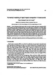
In order to demonstrate the capabilities of the applied damage prediction procedure, an actual impact on the slat has been simulated. The information about the damage on the slat structure has been taken from Internal written communication with Croatia Airlines (2009). Regrettably, important input variables such as initial velocity, aircraft angle of attack and bird mass are not exactly known. However, it is known that the investigated bird strike occurred during the landing phase of the flight. This information enables estimation of velocity, aircraft attitude and slat deflection angles, as those parameters are identifiable for a particular medium range passenger aircraft. The mass of the impacting bird has been assumed to be 0.45 kg, based on the fact that most of the bird strikes in the operating environment of the particular aircraft involve collisions with crows, as stated in Internal written communication with Croatia Airlines (2009). The average mass of a crow has been taken from Lawrence (1973). Taking into account the approximate landing glide slope, wing incidence angle and aircraft pitch angle, the angle of attack (the angle between the chord line of the wing and the free airstream velocity) has been assumed to be 15˚. The slat has been assumed to be in the medium deflection position (-18˚), resulting in a total angle of attack of -3˚ with regard to the slat reference plane, as illustrated by Fig. 6, left-hand image. Additionally, the initial velocity vector is deflected by 28˚ with regard to the longitudinal axis of the slat as to take into account the sweep angle of the wing. Furthermore, bird velocity has been neglected and the bird model longitudinal axis is parallel to the vector of the airflow. The CEL model for this analysis is shown on Fig. 6, right-hand image. The volume containing Eulerian elements is represented by a cube having dimensions 1 x 1 x 1 m. The element length is 12 mm, resulting in 571787 ECD8R elements. Fig. 7 illustrates a sketch of the observed damage caused by the collision with the bird. The bird impacted between ribs number 2 and 3 (as explained by Fig. 1) causing deformation of the upper skin with a maximum depth of 7 mm. No penetration of the slat skin has been observed. Variation of initial velocity magni-
208
Copyright © 2010 Tech Science Press
CMES, vol.70, no.2, pp.191-215, 2010
tude, until acceptable match of numerically predicted and observed damaged states has been achieved, revealed that the initial velocity has been approximately 90 m/s (324 km/h) what corresponds to the usual flight parameters in this phase of the flight. During the variation of the initial impactor velocity, all other input variables have been held constant, having values as previously explained. All results on the slat model in this work have been calculated for an initial velocity of 90 m/s. Deformation of the Eulerian bird impactor at particular time measured in [ms] is shown on Fig. 8. The advantages of the CEL formulation compared to the pure Lagrangian approach, presented in Smojver and Ivancevic (2010), are clearly noticeable, as the Eulerian bird model efficiently captures extreme deformation problems. On the other hand, application of the Lagrange impactor model has restrictions on the highest velocity at which the bird finite element model can be examined. The critical impact velocity magnitude for the Lagrangian bird model is approximately 150 m/s, depending on the target geometry and attitude of the impactor relative to the target. Further increases of the initial velocity can result in numerical instabilities and errors associated with finite element distortion, as observed by the authors of this paper. The bird impact results in locally very high equivalent stress values, which for short periods of time exceed 400 MPa. Equivalent plastic strain contours of the upper slat skin are shown on Fig. 9. The maximum value of equivalent plastic strain is 3.26%, and thus significantly lower than the failure plastic strain value of the Al 2024-T3 alloy. The dimensions of the slat skin area where significant values of plastic strain appear, are approximately 155 mm x 111 mm, while the plastically deformed skin is 20 mm away from the rib number 2. These values correspond very good to the damage sketched on the damage report. Additionally, no plastic deformation has been predicted on the rib number 2 and on the stringers, what is also in accordance with the damage report. Fig. 10 shows the slat skin displacement contours in the 2 direction that is referred to the slat reference coordinate system as shown on Fig. 6. The total magnitude of deflection is 9.87 mm. Due to the elastic vibrations in the 3 direction, which are still present in the numerical response after the analyzed time period (7 ms), comparison of numerical results and the damage report has been achieved through deflection in the 2 direction. Maximum deflection in the 2 direction at the end of the analysis is calculated to be 7.15 mm, and the shape of deflection contours is elliptical, thus resembling the sketched skin damage contour on Fig. 7, left-hand side image. The deflection in the 2 direction converges to approximately 7 mm, the value which has been stated in the damage report as the highest dent depth. The time history of deflection in the 2 direction at the node with the highest deflection value is shown by Fig. 11, left-hand side image.
An Explicit Numerical Modeling of Soft Body Impact Damage
209
SDV1 SNEG, (fraction = -1.0) (Avg: 75%) +3.261e-02 +2.990e-02 +2.718e-02 +2.446e-02 +2.174e-02 +1.902e-02 +1.631e-02 +1.359e-02 +1.087e-02 +8.154e-03 +5.436e-03 +2.718e-03 +0.000e+00
111
20
155
Figure 9: Equivalent plastic strain contours and dimensions of the slat skin with dimensions of the area with increased plastic deformations in [mm]
U, U2 +7.150e-03 +6.494e-03 +5.838e-03 +5.181e-03 +4.525e-03 +3.869e-03 +3.212e-03 +2.556e-03 +1.900e-03 +1.243e-03 +5.870e-04 -6.929e-05 -7.256e-04
Figure 10: Skin displacement in the 2 direction - in [m]
Figure 11: Comparison of deformed and initial slat cross section (right-hand side image) and diagram of deflection in the 2 direction of the node with highest deflection (left-hand side image)
210
Copyright © 2010 Tech Science Press
CMES, vol.70, no.2, pp.191-215, 2010
Figure 12: Submodel finite element model used in this work
SDV1 SNEG, (fraction = -1.0) (Avg: 75%) +3.898e-02 +3.574e-02 +3.249e-02 +2.924e-02 +2.599e-02 +2.274e-02 +1.949e-02 +1.624e-02 +1.299e-02 +9.746e-03 +6.497e-03 +3.249e-03 +0.000e+00
95
20
125
Figure 13: Equivalent plastic strain values for the Lagrangian bird and submodel with dimensions of the area with increased plastic deformations in [mm]
U, U2 +4.971e-03 +4.512e-03 +4.053e-03 +3.594e-03 +3.136e-03 +2.677e-03 +2.218e-03 +1.759e-03 +1.300e-03 +8.413e-04 +3.825e-04 -7.637e-05 -5.352e-04
Figure 14: Slat skin deflection calculated by the Lagrangian bird and submodel in [m]
211
An Explicit Numerical Modeling of Soft Body Impact Damage
S, Mises SNEG, (fraction = -1.0) (Avg: 75%) +4.000e+08 +3.667e+08 +3.333e+08 +3.000e+08 +2.667e+08 +2.333e+08 +2.000e+08 +1.667e+08 +1.333e+08 +1.000e+08 +6.667e+07 +3.333e+07 +0.000e+00
t= 1 ms
t= 2 ms
t= 3 ms
t= 4 ms
Figure 15: Deformation of the Lagrangian bird during the impact. Contours of equivalent Von Mises stress are shown in [Pa]
Fig. 11 right-hand side image shows a comparison of the impacted and genuine slat cross sections, as predicted by the numerical simulation. Regrettably, no details are given about the exact shape of the dent, as only the maximum dent depth has been provided in the damage report [Internal written communication with Croatia Airlines (2009)]. To demonstrate the versatility of the presented bird strike damage prediction procedure, the impact event has also been simulated on the submodel in a combination with the Lagrange bird model. The slat structure has been created by setting the model reduction distance to be 1.5 m away from the location of the impacted node. Using these parameters in LESAD, the total number of elements has been reduced from 31350 to 18891. In order to substitute the effects of the missing model, additional boundary conditions have to be included in the analysis of the submodel. This has been achieved by restraining translational degrees of freedom in the 1 direction of the nodes at the newly created model boundary. The submodel finite element model is shown on Fig. 12. The Lagrangian 0.45 kg bird model has been discretized by 532 hexahedral finite elements.
212
Copyright © 2010 Tech Science Press
CMES, vol.70, no.2, pp.191-215, 2010
As illustrated by Fig. 13 and Fig. 14, the combined application of the Lagrangian bird model and the submodeling approach is not completely able to replicate the damage contours and output values calculated by the CEL formulation on the complete flap model. The magnitude of equivalent plastic strain is 3.90 % (opposed to 3.26%), and the deflection in the 2 direction is 4.97 mm (compared to 7.15 mm). The calculated dimensions of the area having increased plastic deformation are approximately 125 x 95 mm (contrary to 155 x 111 mm). Fig. 14 shows high values of deflection near the end of the slat structure (rib number 1), which are a result of the global vibration of the slat model still present at the end of the analysis. The impact of the Lagrangian bird on the slat submodel is illustrated by Fig. 15. The deformation of the impactor finite element mesh reveals the greatest disadvantage of this bird modeling approach. Despite utilizing the same constitutive model, the Lagrangian impactor is not able to effectively replicate the extreme deformations needed to illustrate real bird behavior during the impact. Consequently, the Lagrangian impactor is not able to correctly transfer the impacting loads on the slat structure, leading to an underestimation of deflection magnitudes. This effect is the least obvious at impact conditions in which the initial velocity vector is perpendicular to the target but gains increased importance as the impact becomes more oblique. This explains the good results obtained by the Lagrangian bird model in Section 5, where the bird impacts normal to the target plate. As the impact on the streamlined slat structure significantly differs from perpendicular impact conditions, the effect of unrealistic impactor behavior results in poor match with results obtained by the CEL model. Despite relatively poor match with the observed damage from the damage reports, the combination of the submodeling approach and the Lagrangian bird model is a computationally very efficient method to get a fast insight in the damaging process during a bird strike on complicated structural finite element models. The combined usage of the two different impactor models can thus be regarded as supplementary methods, as the pure Lagrangian formulation can be used to estimate unknown initial conditions which are then used as input variables for the hybrid (CEL) approach to calculate more realistic results. The complete analysis on the substructure model has been performed in 30 minutes, compared to approximately 8 hours for the CEL formulation on the complete slat model. The analyses have been executed on an eight-core desktop workstation. The effect on computational time using the submodeling approach and the Lagrangian impactor model is roughly proportional to the reduction in the number of finite elements. The combination of the Eulerian impactor and submodeling approach is also possible, but the effect on computational time reduction is negligible as the increased computational time in CEL analyses is caused by the large number of Eulerian elements.
An Explicit Numerical Modeling of Soft Body Impact Damage
7
213
Conclusions
This paper demonstrates the enhancements in the bird strike damage prediction procedure compared to the results presented in the previous paper [Smojver and Ivancevic (2010)]. The main improvement has been accomplished by replacing the Lagrange bird model with the Eulerian bird model, which has been achieved by utilizing Abaqus’ Coupled Eulerian Lagrangian technique. This modeling technique enables better capturing of the fluid-like bird behavior upon impact in the velocity range at which bird strikes usually occur. The fact that the Eulerian model doesn’t suffer from numerical instabilities caused by extreme material deformation, improves numerical stability of the analysis and enables more realistic prediction of damage on the impacted structure. The submodeling procedure presented in Smojver and Ivancevic (2010) has been further developed in order to be able to generate CEL models without the time-consuming usage of Abaqus/CAE. The combination of the pure Lagrangian approach to the bird strike problem and the submodeling procedure is a computationally very cost-efficient method to get insight in the damage process, although the accuracy of such analyses is questionable. This combination can be regarded as a preceding step to the CEL simulation, since initial conditions (impact location, initial velocity, impactor attitude etc.) can be quickly predicted. As the main focus of the presented work is damage prediction in metallic aeronautical structures, strain rate effects in the constitutive model of aluminum alloys have been included in the analyses. These effects must not be neglected in bird strike simulations as the response of aluminum alloys at increased strain rates greatly differs from the quasi-static response. Without inclusion of strain rate effects, the calculated maximum deflection in the 2 direction for the CEL model and complete slat model is 10.34 mm (compared to 7.15 mm with inclusion of strain rate effects). These results clearly indicate the importance of inclusion of strain rate effects in the behavior of metallic structural items during impacts in the medium velocity range. Acknowledgement: This research has been financially supported by the Ministry of Science, Education and Sports, Republic of Croatia through the scientific project “Numerical Modelling of Nonisotropic Continua” and Technological Project “Numerical Modelling of Impact Damage in Aeronautical Structures”. The authors would also like to express their gratitude to Dr.Sc. Milan Vrdoljak, who developed the flight mechanics subroutines for LESAD. References Abaqus Analysis User’s Manual (2008), Version 6.8. Dassault Systémes.
214
Copyright © 2010 Tech Science Press
CMES, vol.70, no.2, pp.191-215, 2010
Airoldi, A.; Cacchione, B. (2006): Modelling of impact forces and pressures in Lagrangian bird strike analyses. Int. J. Imp. Eng., vol. 32, pp. 1651-1677. Benson, D.J.; Okazava S. (2004): Contact in a multi-material Eulerian finite element formulation, Comp. Methods Appl. Mech. Eng., vol. 193, pp. 4277 - 4298. Campbell, J.C.; Vignjevic, R.; Patel, M.; Milisavljevic, S. (2009): Simulation of water loading on deformable structures using SPH. CMES: Computer Modeling in Engineering & Sciences, vol. 49, no. 1, pp. 1–22. Chizari, M.; Barrett, L.M.; Al-Hassani, S.T.S (2009): An explicit numerical modelling of the water jet tube forming. Comp. Mater. Sci., vol. 45, pp. 378-384. Echenfelder, P.F. (2005): High speed flight at low altitude: Hazard to Comercial Aviation?. Birdstrike Commitee Proceedings. Georgiadis, S; Gunnion A.J.; Thomson, R.S.; Cartwright, B.K. (2008): Birdstrike simulation for certification of the Boeing 787 composite moveable trailing edge. Compos. Struct., vol. 86, pp. 258-268. Guida, M.; Grimaldi, S.; Marulo, F.; Meo, M.; Olivares, G. (2009): Bird Impact on Leading Edge Wing with SPH Formulation. 17th International Conference on Composite Materials. Guida, M.; Marulo, F.; Meo, M.; Riccio, M. (2008): Analysis of Bird Impact on a Composite Tailplane Leading Edge. Appl. Compos. Mater., vol.15, pp. 241 – 257. Hanssen, A.G.; Girard, Y.; Olovsson, L.; Berstad, T.; Langseth, M. (2006): A numerical model for bird strike of aluminium foam-based sandwich panels. Int. J. Imp. Eng., vol. 32 pp. 1127-1144. HexWeb Honeycomb Attributes and Properties (1999.), Hexcel Composites. Hsu, S.S.; Jones, N. (2004): Dynamic axial crushing of aluminium alloy 6063 -T6 circular tubes. Lat. Am. J. Solids Struct., vol. 3, pp. 277-296. Ianucci, L.; Donadon, M. (2006): Bird Strike Modeling Using a New Woven Glass Failure Model. 9th International LS-DYNA Users Conference. Internal written communication with Croatia Airlines (2009). Johnson, A.F.; Holzapfel, M. (2003): Modelling soft body impact on composite structures. Compos. Struct., vol. 63, pp. 103-113. Lavoie, M.A.; Gakwaya, A.; Nejad Ensan, M.; Zimcik, D.G. (2007): Review of existing numerical methods and validation procedure available for bird strike modeling. International Conference on Computational & Experimental Engineering and Sciences. Lawrence, J.H. (1973): Windshield Bird Strike Structure Design Criteria. Air
An Explicit Numerical Modeling of Soft Body Impact Damage
215
Force Flight Dynamics Laboratory, Technical report AFFDL-TR-73-103. McCarthy, M.A.; Xiao, J.R.; Petrinic, N.; Kamoulakos, A.; Melito, V. (2004): Modelling of Bird Strike on an Aircraft Wing Leading Edge Made from Fibre Metal Laminates – Part 1: Material Modelling. Appl. Compos. Mater., vol. 11, pp. 295 – 315. Metallic Materials and Elements for Aerospace Vehicle Structures MIL-HDBK5J (2003), Department of Defence Handbook, Washington, DC. Smojver, I; Ivancevic, D. (2010): Numerical simulation of bird strike damage prediction in airplane flap structure. Compos. Struct., vol. 92, pp. 2016 - 2026. Tho, C.H.; Smith, M.R. (2008): Accurate bird strike simulation methodology for BA609 tiltrotor. Presented at the American helicopter society 64th annual forum. Vignjevic, R.; Reveles, J.R., Campbell, J. (2006): SPH in a total Lagrangian formalism. CMES: Computer Modeling in Engineering & Sciences, vol. 14, no. 3, pp. 181–198. Welsh, C.J.; Centoze, V. (1986): Aircraft transparency testing - artificial birds. Arnold Engineering Development Center, Report AEDC-TR-86-2. Wilbeck, J.S. (1977): Impact behavior of low strength projectiles. Air Force Materials Laboratory, Technical Report AFML-TR-77-134. Zukas, J.A.; Nicholas, T.; Swift, H.F.; Greszczuk, L.B.; Curran, D.R. (1992): Impact Dynamics. Krieger Publishing Company.