deforming bodies, 2) computing impact forces when bodies collide, and 3) ... without payment of fee is granted for nonprofit educational and research purposes ...
MITSUBISHI ELECTRIC RESEARCH LABORATORIES http://www.merl.com
A Computationally Efficient Framework for Modeling Soft Body Impact
Sarah F. Frisken, Ronald N. Perry
TR2001-11
December 2001
Abstract While there has been significant progress in simulating collisions between rigid bodies, much remains to be done for modeling interactions between soft bodies. Graphical techniques for representing and deforming soft bodies range from non-physical (e.g., control point-based) to physically plausible (e.g., FFD) to physically realistic (e.g., FEM). All of these techniques require three operations to model interactions between soft bodies: 1) detecting collisions between deforming bodies, 2) computing impact forces when bodies collide, and 3) determining deformation forces or contact deformation of the bodies to initialize a deformation technique. In this report, we propose a new framework which performs all three operations quickly, with efficient use of memory, and more accurately than previous methods. The results of these operations can be used in any of the deformation techniques mentioned above. SIGGRAPH 2001 Conference Abstracts and Applications
This work may not be copied or reproduced in whole or in part for any commercial purpose. Permission to copy in whole or in part without payment of fee is granted for nonprofit educational and research purposes provided that all such whole or partial copies include the following: a notice that such copying is by permission of Mitsubishi Electric Research Laboratories, Inc.; an acknowledgment of the authors and individual contributions to the work; and all applicable portions of the copyright notice. Copying, reproduction, or republishing for any other purpose shall require a license with payment of fee to Mitsubishi Electric Research Laboratories, Inc. All rights reserved. c Mitsubishi Electric Research Laboratories, Inc., 2001 Copyright 201 Broadway, Cambridge, Massachusetts 02139
MERLCoverPageSide2
A Computationally Efficient Framework for Modeling Soft Body Impact Sarah F. Frisken and Ronald N. Perry, MERL
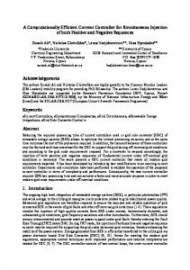
force vector, FV, acting on V due to penetration SU of U by V is approximated by the sum of forces fVi = kU(xi)distU(xi)g(xi), where kU(x) is the SV f material stiffness of U at x, distU(x) is the closf est distance from x to the surface of U, and g(x) f is the normalized gradient vector of U’s disf tance field at x. f Figure 2. Forces acting The intersection ADF represents the volumetric on SV in the overlap overlap region to high precision. Previous region of Figure 1A. penalty methods compute FV from a small number of points restricted to the penetrating surface. Using ADFs, penetration forces can be computed over the surface or the volume of the overlap region. Forces can be computed at an arbitrary number of well-spaced sample points seeded on the surface or throughout the volume and we are investigating methods to analytically interpolate forces throughout the overlap region. These advantages of ADFs provide the opportunity to compute impact forces more accurately than previous methods. f V1 f V2
f V3
V4
Introduction While there has been significant progress in simulating collisions between rigid bodies [1], much remains to be done for modeling interactions between soft bodies. Graphical techniques for representing and deforming soft bodies range from non-physical (e.g., control point-based) to physically plausible (e.g., FFD) to physically realistic (e.g., FEM) [2]. All of these techniques require three operations to model interactions between soft bodies: 1) detecting collisions between deforming bodies, 2) computing impact forces when bodies collide, and 3) determining deformation forces or contact deformation of the bodies to initialize a deformation technique. In this sketch, we propose a new framework which performs all three operations quickly, with efficient use of memory, and more accurately than previous methods. The results of these operations can be used in any of the deformation techniques mentioned above. Utilizing ADFs for Modeling Soft Body Impacts We recently proposed adaptively sampled distance fields (ADFs) as a new shape representation and suggested that they might be useful for collision detection [3]. ADFs adaptively sample the signed distance field of an object and store the sample values in a spatial hierarchy (e.g., an octree) for fast processing. ADFs have several advantages for modeling impacts between soft bodies including: 1) compact representations of complex surfaces, 2) trivial inside/outside and proximity tests, 3) fast localization of potential contact regions, 4) more accurate representation of the overlap region, and 5) simple methods for computing material-dependent contact deformation. Detecting Collisions, Penetration, and Proximity The sign of the distance reconstructed from the ADF at any point in space provides a trivial inside/outside test. When detecting collisions between two ADFs, their spatial data structures can be exploited to quickly localize potential regions of overlap. Within these regions, a new ADF of the shape defined by the intersection of the two ADFs is locally generated as illustrated in Figure 1A. (The intersection is a simple min() operation on the distance fields of the two ADFs.) If the intersection ADF is non-empty, a collision is detected and the region is further processed. To test for proximity rather than collisions, an ADF defined by the intersection of offset surfaces can be generated as illustrated in Figure 1B. Computing Impact Forces There are a number of methods for computing impact forces between two interacting bodies [4]. Penalty-based methods compute impact forces based on how far objects penetrate each other during a discrete time step. Distance fields have been used [5, 6] to determine penetration depth at sample points along the penetrating surface as well as to compute contact forces. From Figure 2, the total
U
V SV
A
U
V5
V6
V7
V8
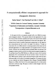
Determining Contact Deformation When using ADFs, there are two methods for determining the initial contact deformation. The first follows common practice and uses the impact forces computed above together with a deformation technique. The second uses the implicit nature of distance fields to compute contact deformation by combining the distance fields within the overlap region. Various methods can be used to combine the fields and achieve material dependent deformation [7, 8] (see Figure 3). Figure 4 shows a simulation for the impact of two soft bodies.
U
V
A
U
B
V
U
V
C
Figure 3. Contact deformation of the objects of Figure 1 with A) similar material densities, B) V softer than U, and C) volume preserving deformation (after [7, 8]).
References [1] M. Lin and S. Gottschalk, "Collision detection between geometric models: a survey", Proc. IMA Conference on Mathematics of Surfaces, 1998. [2] S. Gibson and B. Mirtich, "A survey of deformable modeling in computer graphics", MERL Technical Report, TR97-19, 1997. [3] S. Frisken, R. Perry, A. Rockwood, and T. Jones, "Adaptively sampled distance fields: a general representation of shape for computer graphics", Proc. SIGGRAPH'00, pp. 249-254, 2000. [4] A. Witkin, D. Baraff and M. Kass, “An introduction to physically based modeling”, SIGGRAPH Course Notes 32, ACM SIGGRAPH, 1994. [5] S. Frisken-Gibson, "Using linked volumes to model object collisions, deformation, cutting, carving, and joining", IEEE TVCG, pp. 333-348, 1999. [6] K. Hoff, A. Zaferakis, M. Lin, D. Manocha, "Fast and simple 2D geometric proximity queries using graphics hardware", Proc. Interactive 3D Graphics'01, 2001. [7] M. Desbrun and M-P. Gascuel, "Animating soft substances with implicit surfaces", Proc. SIGGRAPH'95, pp. 287-290, 1995. [8] M-P. Cani-Gascuel, "Layered deformable models with implicit surfaces", Proc. Graphics Interface'98, pp. 201-208, 1998.
V
SU
B
Figure 1. A) The overlap region (in blue) of shapes U and V is determined by local generation of the intersection of U and V. B) The overlap region of the offset surfaces of U and V can also be easily generated for determining proximity information.
A B Figure 4. Indentation of a sphere after impact with an ADF of a complex cow model. Contact deformation of the sphere after impact with A) a soft cow and B) a hard cow.
Model-A and Model-B
ADF-A and ADF-B
ADF Generator
Generation Parameters
Process Next Time Step
Determine potential overlapping regions of ADF-A and ADF-B using their respective spatial data structures (e.g., octrees)
Overlapping Regions
Within the overlapping regions, generate a new ADF, ADF-Int, which represents the intersection of ADF-A and ADF-B
Generation Parameters. The distance function reconstructs the distances at a requested location for ADF-A and ADF-B and then determines the minimum of the distances.
ADF-Int
Compute Forces
Force computation method: sample surface, sample volume, analytic integration
Forces
Using a physical simulator, alter the ADFs according to the forces. Then proceed to the next time step.
A data flow diagram for a system computing forces from the intersection ADF; the resulting forces serve as input to a physical simulator which determines the deformed shapes for the current time step.
Model-A and Model-B
ADF-A and ADF-B
ADF Generator
Generation Parameters
Process Next Time Step
Determine potential overlapping regions of ADF-A and ADF-B using their respective spatial data structures (e.g., octrees)
Overlapping Regions
Reconstruct distances and gradients for ADF-A and ADF-B at a requested location
Generate new cells in ADF-A within the overlapping regions according to the material properties of ADF-A and ADF-B and the deforming procedure. Generate new cells in ADF-B within the overlapping regions according to the material properties of ADF-A and ADF-B and the deforming procedure. Then proceed to the next time step.
Material properties of ADF-A and ADF-B and a deforming procedure which computes a new distance value at a requested location according to the material properties of ADF-A and ADF-B at that location and the distances and gradients of ADF-A and ADF-B at that location.
A data flow diagram for a system that deforms interacting bodies represented as ADFs by applying a deformation (blending) procedure on the ADFs.
Model-A and Model-B
ADF-A and ADF-B
ADF Generator
Generation Parameters
Process Next Time Step
Determine potential overlapping regions of ADF-A and ADF-B using their respective spatial data structures (e.g., octrees)
Overlapping Regions
Reconstruct distances and gradients for ADF-A and ADF-B at a requested location
Generate new cells in ADF-A within the overlapping regions according to the material properties of ADF-A and ADF-B and the deforming procedure, producing ADF-A'. Generate new cells in ADF-B within the overlapping regions according to the material properties of ADF-A and ADF-B and the deforming procedure, producing ADF-B'.
Material properties of ADF-A and ADF-B and a deforming procedure which computes a new distance value at a requested location according to the material properties of ADF-A and ADF-B at that location and the distances and gradients of ADF-A and ADF-B at that location.
ADF-A' and ADF-B'
Use deformed shapes ADF-A' and ADF-B' as initial input to a physical simulator which determines the final deformed shapes. Then proceed to the next time step.
Material properties of ADF-A and ADF-B
A data flow diagram for a system that deforms interacting bodies represented as ADFs by applying a deformation (blending) procedure on the ADFs; the resulting ADFs serve as input to a physical simulator which determines the final deformed shapes.