about best architectures are going on. A model ... In central architectures, the groupware application runs on a central server. This archi- ..... dedicated server.
An extensible classification model for distribution architectures of synchronous groupware Jörg Roth, Claus Unger University of Hagen, Department for Computer Science, 58084 Hagen, Germany
Abstract. In this paper we present a new classification model for distribution architectures of synchronous groupware. Former models divide distribution architectures into centralized, replicated and hybrid ones. Such a classification is not expressive enough to argue about pros and cons of a specific realisation, thus in the past discussions about distribution architectures were very emotional. Discussions about best architectures are going on. A model with stronger expressiveness would help to clear up this discussion. Our classification model distinguishes five basic architectures and several subtypes. It allows discussing aspects of distribution architectures in detail. We used this model to classify some groupware platforms. A list of criteria at the end of this paper demonstrates the influence of specific architectures on groupware usage. Keywords: Computer Science/CSCW, synchronous groupware, theoretical study, CSCW architectures, modelling
1 Introduction Synchronous groupware brings together users which are geographically distributed and connected via a network. There exist a variety of platforms, e.g. Groupkit [24], COAST [29], Habanero [20], which relieve the groupware developer from struggling with standard problems like network details, synchronization algorithms, etc., and allow him or her to concentrate on application-specific details. A significant distinctive feature of groupware is the distribution architecture, which defines, which parts of a groupware application run on a central server, which parts run on decentral sites and how sites are logically linked which each other. Choosing a specific distribution architecture has an important influence on how groupware can be developed and used. The distribution architecture has affects on several topics, to mention some: application's response time and fault tolerance can be improved using decentralized architectures. In general, decentralised architectures scale much better than centralized. On the other hand, some runtime services such as storing documents can be developed much easier, if a distribution architecture with a central server is used. Many designers of groupware focus on the distribution architecture when presenting their platforms. Unfortunately the terms defining a specific distribution architecture are extremely vague. The classical approach to describe distribution architectures (e.g. in [1], [4], [15], [26]), distinguishes between two types:
• In central architectures, the groupware application runs on a central server. This architectures often are called single-site execution. • In replicated architectures, the groupware application runs on each user's site (multi-site execution). These definitions are based on projects, in which original single-user applications are used inside a collaborative environment. Since such applications have no additional code for performing group-oriented services, they are called collaboration-transparent [16]. Such applications cannot be divided into components, usually such single-user applications are applications 'of-the-shelf' - no source code nor program documentation for modifications are available. On one hand, well-known collaboration-transparent application with high quality reduce learning efforts for end-users. On the other hand, the lack of collaboration services can be viewed as a big disadvantage. Applications specially designed for group environments (so-called collaboration aware applications), offer more possibilities for distributing their components. Thus a set of new distribution architectures were introduced: • Hybrid or semi-replicated architectures divide applications into components which run centralized as well as replicated. Meanwhile several platforms exist which offer different distribution architectures. Unfortunately, the above classification into three types allows no detailed argumentation about advantages and disadvantages of specific architectures. Most of the newer platforms, which support collaboration aware applications, have to be summarized under the architecture hybrid, though there exist big differences between them. The problem becomes even worse, when we take different services of groupware platform into account. There are different stages of collaboration, which have to be supported by a platform, e.g. preparing a session, joining a session, running the collaborative application, storing persistent artefacts. Each stage may have its own distribution architecture, e.g. an artefact can be stored centrally on a server, but the collaborative application runs replicated. Assigning one single distribution architecture (e.g. hybrid) to a specific platform means blurring the details. The current discussion about distribution architectures is ongoing. Many new platforms present new architectures. To discuss pros and cons of architectures in more detail, a new classification model has to be introduced, which provides a richer expressiveness than the centralized-replicated-hybrid classification. Before we present our own classification model, we discuss some related models. 2 Related work Patterson's taxonomy [21] was one of the first architectural models for synchronous groupware. The model assumes that the primary task of a groupware application is to maintain consistency in shared states. Patterson divides groupware applications into four layers.
a) shared model
b) shared view
c) hybrid
File
File
File
File
Model
Model
Model
Model
View
View
View
View
View
View
Display
Display
Display
Display
Display
Display
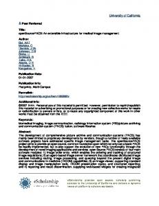
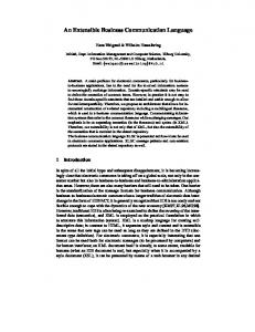
Figure 1: Variations of Patterson's taxonomy [21]
The display is directly linked to the user, the view contains the display's logical presentation, the model describes the internal, transient state and the file describes the persistent state of the application. Patterson's taxonomy distinguishes four layers, even if in a concrete implementation some layers are merged together or left out completely. Patterson allows to specify, which of these components are located on a central server and which run on the user's site. As a result of 'unzipping' Patterson's architecture from the bottom, distribution architectures are implicitly defined. Figure 1a) shows an architecture with a shared state, i.e. the model and file layer are hosted by a central server. Figure 1b) shows an architecture without a central server. All layers run replicated without a need for a central server; model and view are synchronised. Figure 1c) finally shows a hybrid architecture which needs a central server but allows synchronization between the view components. Patterson admits that continuous data streams (e.g. audio, video) can be modelled only inadequately in his taxonomy. Dewan's generic architecture [6] can be viewed as a generalization of Patterson's taxonomy. Dewan's architecture has no fixed number of layers. As in Patterson's taxonomy, Dewan's architecture allows 'unzipping' from the bottom. Dewan distinguishes replicated and shared layers. Data flow is modelled by events, which can be transferred between layers in an horizontal or vertical manner. 3 An alternative classification model 3.1 A model for describing distribution architecture To describe distribution architectures, we could in principle use Patterson's taxonomy or Dewan's generic architecture. The degree of 'unzipping' an architecture defines, which component is placed on a central server or a decentral site. However, both models are not expressive enough to describe different architectures in detail. In the following, we present a model solely designed for describing distribution architectures. The model consists of two parts: the application scheme and the distribution scheme. The application scheme defines the components of groupware applications and the distribution scheme defines, how these components can be distributed among sites.
Application Core Functional Core
Presentation
Window System
Coordination
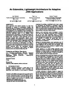
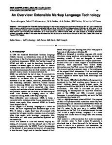
Figure 2: The application scheme
Figure 2 shows the application scheme. A groupware application according to this model consists of three components: • The application core presents the application's function. It is divided into the components functional core and presentation. • The window system displays the application's windows and receives user events from e.g. from keyboard and mouse. • The coordination is responsible for running the application in a distributed environment. Coordination tasks are, e.g., synchronisation of user input, concurrency control, floor control, etc. Links between components indicate data flow. In contrast to Patterson's taxonomy, there is no file component. Persistence aspects, if any are subsumed under the functional core. This application schema was influenced by the single user model Arch [32]. Arch components correspond to components of the application scheme in the following ways: • Arch's functional core and domain adapter correspond to the functional core, • Arch's dialogue component and presentation component correspond to the presentation component, • Arch's interaction toolkit component corresponds to the window system. There is no counterpart in Arch to our coordination component, since the Arch model was designed for single-user applications only. In the following, we use this model according to the following set of rules: • Not all links between components need to exist. • The coordination component is not always necessary. In such a case, coordination tasks are performed by the application core component. • The window system is left out, if it has no special meaning inside a distribution architecture. In these cases, users and presentation are linked together. • Depending on the architecture, the internal components of application cores may be hidden. If on the other hand internal components are displayed, the application core's frame can be left out to clarify the diagram. The components of an application scheme can be distributed according to a distribution scheme. Figure 3 shows the basic distribution schemes:
a) central components
d) asymmetrical
b) direct communication
c) hybrid
e) multiple servers
...
...
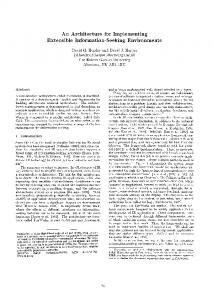
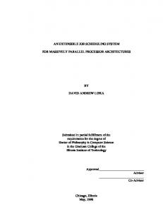
Figure 3: Basic distribution types
A rectangle presents one or more components described in the application schemes. Dotted frames indicate different sites inside a network. In the following, sites which are assigned to a user are called peers, other computers are called servers. Components hosted by peers are called decentralized components, components hosted by servers are called centralized components. Corresponding decentralized component are called replica. The following basic distribution architectures exist in our model: a) Architectures with centralized components: these architectures have at least one centralized component. Peers are not connected to each other. b) Architectures with direct communication: these architectures have no central component at all. All peers are connected to each other. c) Hybrid architectures: these architectures have at least one central component and allow direct communication between peers. d) Asymmetrical structures: have no central component, but distribution of components among peers is not symmetrical, i.e. at least one peer component has no replica. e) Multiple servers: these architectures use more than one server, i.e. central components are distributed to more than one site. In the following, we present different variations of each basic architecture. The list of architectures may not be complete. New platforms possibly introduce new distribution architectures, thus the list of basic architectures and subtypes may have to be extended in the future. To reference a certain distribution architecture, we introduce the following abbreviations: • An uppercase letter indicates the basic distribution types: C: central components, D: direct communication, H: hybrid, A: asymmetrical, M: multiple servers. We will introduce two more types, P and Q, later. • A digit (1, 2 or 3) indicates a subtype. • Lowercase letters indicate different variations of a subtype.
A specific distribution architecture could be referenced, e.g. by the abbreviation H2b. Same subtype numbers across different basic type indicate resemblance. E.g. architectures C2, D2 and H2 have similar characteristics, although they were derived from different basic types. 3.2 Architectures with centralized components Figure 4 shows architectures with centralized components. Dotted frames which combine components from the same site are left out in the following. a) C1: centralized application (collaboration transparent)
b) C1b: centralized application (collaboration aware) Functional Core
Application Core
Window System
Präsentation
Window System
c) C2: centralized state Functional Core
Presentation
Presentation
Window System
Präsentation
Window System
d) C3: centralized coordination Coordination
Application Core
Application Core
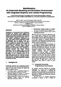
Figure 4: Architectures with central components
Centralized collaboration-transparent application (C1) Figure 4a) shows an application, which runs on a central server. The output is distributed via a window system such as X-Windows. X-Windows is an ideal window platform for such purposes, because its protocol specification is public [28] and allows individual extensions. X-Windows usually runs on Unix platforms and allows to separate an application from the corresponding window output, e.g. one can start an application on a fast machine with much memory and conveniently control the application on his or her desktop computer. A modification of the X-Windows protocol allows to distribute graphical output to more than one computer and an application can be used inside a group of users. Any user input is collected and passed on to the application. The distribution of window output on the one hand, and the collection of user input on the other hand is done by a virtual window manager, which runs on the server. Via this architecture, any X-Windows program can be used inside a group environment without modification. The disadvantage of this architecture is the lack of coordination between users. It is possible to make conflicting input, e.g. two users drag the same scroll-
bar into different directions (so-called scroll wars). It is not possible for an application to detect conflicting situations, nor react in an appropriate manner. Groupware platforms based on this architecture are e.g. Shared-X [12] and XTV [2]. This architecture is often considered as the epitome of the centralized architecture. Collaboration-aware central application (C1b) The architecture in figure 4b) attempts to offset the disadvantage of architecture C1 only to support collaboration-transparent applications. The application still runs on a central server, but separate presentation components generate individual output for each user. This architecture has, e.g., been realised in the Rendezvous system [14]. Separate presentation components can be used in two ways: first, every user can choose his own view on the same data; if, e.g., data present statistics, one user can choose a pie chart, another a bar chart to display the same data. Secondly, additional output can be used to achieve group awareness. Presentation components can communicate which each other and can generate overview views, telepointers etc. In contrast to C1, an application has to be developed explicitly for this architecture. Both C1 and C1b are limited to operating systems which support window systems such as XWindows. Systems based on Windows or MacOS cannot simply be used as peer computers. Another disadvantage is the amount of data, which has to be transferred between sites. To present window contents on peer sites, a big amount of graphical information has to be transferred (e.g. bitmap images), thus C1 as well as C1b can only be used inside a local area network. Centralized state (C2) The architecture displayed in figure 4c) separates the functional core from the presentation. Only the functional core is managed by a server. C2 architectures, in contrast to C1 and C1b, can be implemented on operating platforms without special window systems. Between server and peer, only state information has to be exchanged, any graphical output is computed inside the presentation components. The amount of data transferred between server and peers is much smaller than in C1 and C1b, thus this architecture can be used in sub-optimal network environments. Since the state is centralized and the presentation components are decentralized, this architecture is often called semi-replicated. A groupware platform based on this architecture is, e.g., Clock ([19], [9]). As discussed in [11], one problem related to this architecture is the time-critical path between server and sites. It is difficult for the server to make state information available in real-time. Caches, attached to the presentation components, can help to improve real-time characteristics. Administering decentralized data caches requires a complex protocol which keeps track on consistency of cache contents. Centralized coordination (C3) In architecture presented in figure 4d), the functional core is installed at the peers, only a coordination component runs on a central server. The coordination component's main task is to ensure data consistency of the decentralised states. The Habanero platform [20], e.g., uses the central server to order all events from the peers, which possibly change data. Any event, coming from a peer is first directed to the server which in turn distributes it back to the peers. Since the server reads events one after the other, all peers receive events in the same order. This simple mechanism ensures same states on all peer sites. Unfortunately, an event needs a round-trip peer-server-peer before it can be computed. This compensates the advantage of decentralised states, which originally should improve response time.
3.3 Architectures with direct communication Figure 5 shows architectures with direct communication links between peers. a) D1: decentralized application
b) D2: replicated state
Application Core
Application Core
Coordination
Coordination
Functional Core
Functional Core
Window System
Window System
Presenation
Presenation
c) D2b: replicated state with connected d) D3: decentralized coordination presentation components Functional Core
Functional Core
Coordination
Coordination
Presentation
Presentation
Application Core
Application Core
Figure 5: Architectures with direct communication
Dezentralized application (D1) The decentralized variation of C1 is D1. As in C1, single-user applications can be made accessible for a group via a window system. D1 attempts to limit the amount of data transferred inside the network with decentralized operating applications. On one hand, an architecture with decentralized applications reduces the response time, because the interaction between user and application does not use the network. On the other hand, it is difficult to achieve data consistency. To coordinate access to different replica, decentralized coordination components are used, called conference agents [15]. Simple conference agents allow for one user at a time, to direct input to application. All other users are locked out, i.e. their user input is ignored. With this mechanism, so-called floor control is achieved [7]. Only the user, who holds the floor, is able to control the application. When a user has finished, the floor is passed on to the next user. Even in very simple scenarios, it is very difficult to keep the application's data consistent. There is no way to explicitly access the functional core, thus access has to be done via the application's dialogue interface. The application's internal structure is hidden. To have a chance to keep data consistence, some assumptions are made in [15]: the application's response time has to be nearly the same for all peers. Applications are not allowed to react on the peer's internal states other than managed by the application. Access to local resources such as files, local devices etc., is not allowed. These assumptions are difficult to hold in reality.
In [1] Ahuja et al. compare the architectures D1 and C1 with the help of the Rapport system. The authors conclude that it is nearly impossible, to solve the consistency problems in architecture D1. This architecture is often considered as the decentralized architecture. Replicated state (D2) The architecture shown in figure 5b) separates functional core and presentation. In contrast to C2, the functional core is managed by the peers in a replicated manner. This improves the response time, since local requests can be handled by the peer without network transactions. Communication between sites generally is done by changing shared data. To keep the shared data consistent, synchronisation and concurrency control mechanisms have to be included. This architecture has been realised, e.g. in the platform Clock [19]. Clock's runtime system allows to switch between D2 and C2. Replicated state with connected presentation components (D2b) To solely communicate via the functional core can be viewed as disadvantage. In D2, e.g., to distribute co-ordinates of a telepointer among session partners, requires a shared variable which holds the current pointer position. Every time, the telepointer is moved, this variable has to be changed, which leads to a change of data in all functional cores on other peer sites. Presentation components have to keep track of this variable and have to move the telepointer every time the variable changes. The overhead for this mechanism is very high. The same problem occurs, if continuous data streams such as audio or video have to be handled. Continuous data streams can insufficiently be mapped to data changes. The realtime character of these data leads to other communication mechanisms. Architecture D2b addresses these problems. Instead of communicating via the functional core, the presentation components are connected to each other. This connection can by viewed as bypass for time-critical communication. This architecture has, e.g. been realised in Groupkit [24] and DreamTeam [25]. Decentralized coordination (D3) This architecture corresponds to architecture C3. The replicated coordination component avoids performance bottlenecks caused by a central server. On the other hand, the coordination mechanisms are more complex as in a centralized architecture. This architecture is, e.g., suitable for realising floor control mechanisms. 3.4 Hybrid architectures Hybrid architectures have a central component and at the same time direct communication between peers. There exists a variety of hybrid architectures, from which two variations are presented in the following. Centralized state (H2) Figure 6a) shows a hybrid architecture with has a central state and allows direct communication between presentation components. This architecture has been implemented in the Suite platform [4]. H2 is a mixture of C2 and D2b and combines a simple centralized data management with directly connected presentation components. Another platform based on this architecture is the Notification Server [22]. The Notification Server manages shared data and informs the presentation components about relevant data changes, which in turn update its display (e.g. a window frame).
a) H2: centralized state
b) H3: centralized coordination
Functional Core
Presentation
Presentation
Coordination
Application Core
Application Core
Figure 6: Hybrid architectures
Centralized coordination (H3) Another hybrid architecture is shown in figure 6b). This architecture combines C3 and D3. In contrast to C3 and D3, the architecture H3 allows a direct coupling between applications. This enables the use of continuous data streams as mentioned above. 3.5 Other architectures In the following, some more architectures with special characteristics are described. a) A1: asymmetrical application
b) A2: asymmertrical state
c) A3: asymmetrical coordination
Application Core
Coordination
Coordination
Window System
Window System
Functional Core
Presentation
Presentation
Coordination
Application Core
Application Core
Figure 7: Asymmetrical architectures
Asymmetrical architectures (A) Until now, all peers maintained the same sets of components, only servers might be different from peers. In some cases, it is not necessary, to put centralized components on a dedicated server. Some tasks can be done by a single peer. This leads to asymmetrical architectures as shown in figure 7. In these architectures, there exists a single peer which holds some more components than the other peers. This peer has to be known by other peers. The peer with special tasks can be selected from the set of peers automatically at runtime. Architecture A1 is used e.g. inside the Netmeeting environment [18]. An application runs on one peer. Besides the local user, other users can join in and control the application. The coordination component allows only one user to control the application. Since Netmeeting is based on MS-Windows, it is not possible to use the X-Windows protocol for distributing the application windows. Instead, windows are copied pixel by pixel to other sites.
Other tasks which can be performed by a single peer may manage the functional core (A2) or coordinate the applications (A3). For some tasks related to session management (e.g. joining or leaving a session), it is useful to have one peer for storing special information to coordinate session states. Inside the DOLPHIN platform [27], one peer is responsible for writing the document state to file. The DreamTeam platform [25] uses one peer site for session control. Pairs (P and Q) For some scenarios, it can be useful to limit the number of peers to two. In general, pair architectures can be subsumed under D or A type architectures. We use the letter P to indicate the pair architecture of a corresponding D type and Q for A architectures respectively. E.g. the architecture P1 corresponds to D1 where Q1 corresponds to A1. We do not classify pair architectures based on C. If there are only two peers communicating with each other, the amount of communication links is dramatically reduced. For scenarios with n peers, n ⋅ ( n − 1 ) / 2 connections have to be managed (each peer has to be connected to each other). This results in heavy network load, if the network has no built-in multicast support such as Multicast IP [5]. The case n=2 results in the most simple distribution architecture. Remote maintenance and teleservice software often uses this architecture. One peer can be controlled by another peer, e.g. for administration purposes. With this kind of software, the actual application runs asymmetrically on one peer, thus remote control software has architecture Q1. Some groupware applications allow to switch from an architecture (e.g. type C) to this architecture, if n=2. The video conference software CUSeeMe [31] normally uses a central server (called reflector), to receive and distribute video information. For sessions with only two members, CUSeeMe allows to switch to a pair architecture without any reflector (i.e. to architecture P2b). Multiple servers (M) All architectures above have, if any, only one server. In many cases it is useful to have a set of servers, each of it hosting a component (e.g. the functional core). Figure 8 shows an example. M2: hierarchically distributed state Functional Core
Functional Core
Presentation
Presentation
Functional Core
Presentation
Presentation
...
...
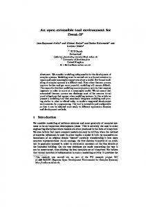
Figure 8: Hierarchical structure
This architecture distributes the functional core to a number of servers, which are hierarchically connected. This can be done for performance purposes; users, e.g., which are closely connected (e.g. inside a LAN) can by grouped together, and different groups are only loosely connected. In this scenario, hierarchical structures have their advantages. A group of
users can access their server very fast inside a LAN, a top-level server connects the different LANs. Algorithms to maintain consistency are very complex since state information is spread among two layers of servers. Variations with multiple servers can be found in real-time channels. In [17] multiple servers are used to efficiently distribute audio and video data. In [3] the CCU algorithm is presented, which achieves data consistency with the help of multiple servers. Besides the hierarchical structure, other structures with multiple servers may be conceived. Serves can be linked together as a ring, or be fully connected. 4 Discussion 4.1 Overview Table 1 outlines all distribution architectures presented in this paper. Table 1: Distribution architectures overview Type C1: centralized application C1b: centralized application C2: centralized state C3: centralized coordination D1: decentralized application D2: replicated state D2b: connected presentation D3: decentralized coordination H2: centralized state H3: centralized coordination A1: asymm. application A2: asymm. state A3: asymm. coordination Q1: asymm. application P2b: connected presentation M2: hierarchically distr. state
collaboration transparent aware aware aware transparent aware aware aware aware aware transparent aware aware transparent aware aware
examples Shared-X, XTV Rendezvous Clock Habanero Rapport Clock Groupkit, DreamTeam Suite, Notification Server Netmeeting DOLPHIN DreamTeam Remote control software CUSeeMe CCU
Our classification model is flexible enough to express new distribution architectures which may be introduced in the future. As described above, our model consists of the application scheme and the distribution scheme, which both can be extended. Inside the application scheme, new components can be identified or existing components can be divided into smaller components. The distribution scheme can be extended in three ways: • add a new basic distribution architecture (i.e. use new uppercase letter), • add a new subtype inside a basic architecture (i.e. use new digit), • add a variation to an existing architecture (i.e. use new lowercase letter). This model can be used to classify a huge set of conceivable distribution architectures. In the end, this classification model is only a means to express and discuss effects of a specific distribution architecture. In the following chapter, we give an overview of aspects related to distribution architectures.
4.2 Effects of distribution architectures on groupware usage and development The discussion about the best distribution architecture for synchronous groupware has a long tradition. Without completeness, this topic was discussed in [1], [4], [8], [10], [11], [13], [15], [22], [23] and [30]. Often distribution architectures are discussed more fiercely and in more detail than architectural styles of groupware applications themselves, such as MVC, ALV or PAC*. Sometimes, distribution architecture have made the crucial point of a groupware platform. Most distribution architectures have advantages as well as disadvantages. In our opinion, there is no best architecture, it's rather a question of how a specific groupware is to be used. In the following, we give a list of criteria to assess a specific architecture. Technical criteria Network related criteria have great influence on the several real-time aspects of a groupware environment. In scenarios with world-wide operating peers or slow network links (e.g. modems), D architectures are more suitable than C or H architectures. If, on the other hand, all sites are placed inside a LAN, network delays can be neglected; thus C architectures have advantages, because they lead to much simpler algorithms. Sometimes, a specific network infrastructure requires a distribution architecture. If, e.g., multicast services are based on native multicast, an architecture with direct connected sites has to be used. Another important criterion is the hardware and operation system platform of peer sites. If, e.g., not all sites are able to run the desired application locally, the architectures C1 or A1 have to be used. If on the other hand standard window toolkits such as X-Windows are not available at peer sites, C1, D1 or A1 cannot be used. Organizational criteria It is always difficult to introduce groupware to a team which has already formed its organizational structure, thus additional demands by the groupware should be avoided. E.g. C or H architectures require a central server, which has to be installed and administered. Some small departments or companies have no administrator, thus central servers would cause organizational problems. In addition, central servers are a cost factor. Normally servers are expensive because they have to be fail proof and perform a high throughput. From the view point of costs, D and A architectures are more suitable. Additional costs can arise from the network infrastructure. If, e.g., sites are connected to the Internet via a service provider, one could be charged according to the amount of network packages sent or received. Architectures based on a windows system (such as C1, C1b, D1 or A1) transfer a huge amount of data between sites, thus would cause high communication costs. Criteria related to groupware development The easiest way to integrate an application into a group scenario is to use applications ofthe-shelf and avoid expensive developments. For collaboration-aware applications, some specific development cannot be avoided. With the help of groupware platforms, the development cycle can be shortened. In addition, the choice for a specific distribution architecture can affect development costs. Architectures with centralized states such as C1b, C2 and H2 allow to handle data management much easier than architectures with replicated states (e.g. D2). Having data stored on a central server allows to keep track on all data manipulation, thus debugging becomes easy. A log can store all state changes for a certain time (e.g. some days), and thus makes it possible to analyse consistency problems. From the view of consistency, distribution architectures with central components lead to easier algorithms than architectures with direct communication.
This list of criteria shows that a choice for a distribution architecture is strongly influenced by the scenario to be realised. A certain architecture may be a suitable for one scenario, but may have many disadvantages in another scenario. 5 Conclusion In this paper we presented a new approach to classify distribution architecture for synchronous groupware. In contrast to former classification models, this model allows to argue about pros and cons of a certain architecture in detail. The model consists of two schemes: an application scheme splits up groupware applications into components and a distribution scheme distributes these components among sites. If in the future, new distribution schemes will be introduced, both schemes can be extended. Many distribution architectures for synchronous groupware have been introduced, all having great influence to corresponding groupware systems. To gain acceptance by end-users, we have to take into account their specific usage scenarios. A choice of criteria presented in this paper shows, how the model can help to reason about distribution architectures. Most architectures have advantages as well as disadvantages. To choose the right architecture, the specific development and usage scenario has to be taken into account. References [1]
Ahuja S. R.; Ensor J. R.; Lucco S. E., A comparison of application sharing mechanisms in real-time desktop conferencing systems, in Proceedings of the Conference on Office Information Systems, ACM COIS '90, Boston, MA, USA, Apr. 25-27, 1990, 238-248
[2]
Abdel-Wahab H. M.; M. Feit, XTV: A Framework for Sharing X Window Clients in Remote Synchronous Collaboration, in Proceedings IEEE Conference on Communications Software: Communications Software: Communications for Distributed Applications & Systems, Chapel Hill, NC, 1991, 159-167
[3]
Cormack G. V., A Calculus for Concurrent Update, Department of Computer Science, University of Waterloo, Waterloo, Canada, 1995, ftp://cs-archive.uwaterloo.ca/cs-archive/CS-95-06
[4]
Dewan P.; Choudhary R., A High-Level and Flexible Framework for Implementing Multiuser Interfaces, ACM Transactions on Information Systems, Vol. 10, No. 4, Oct. 1992, 345-380
[5]
Deering S., RFC 1112: Host Extensions for IP Multicasting, Request For Comments, Aug. 1989
[6]
Dewan P., Multiuser architectures, in Proceedings of IFIP WG2.7 Working Conference on Engineering for Human-Computer Communication, Aug. 1996, 247-270
[7]
Dommel H. P.; Garcia-Luna-Aceves J. J., Floor control for multimedia conferencing and collaboration, Multimedia Systems, Vol. 5, 1997, 23-38
[8]
Greenberg S.; Hayne S.; Rada R. (eds), Groupware for Real-Time Drawing, McGraw-Hill, 1995
[9]
Graham N., The Clock Language: Preliminary Reference Manual, York University, Canada, 1996
[10] Greenberg S.; Roseman M., Groupware Toolkits for Synchronous Work, Department of Computer Science, University of Calgary, Canada, Nov. 1996 [11] Graham N.; Urnes T.; Nejabi R., Efficient Distributed Implementation of Semi-Replicated Synchronous Groupware, Proceedings of the ACM Symposium on User Interface Software and Technology (UIST'96). ACM Press, Seattle, USA, Nov. 1996, 1-10 [12] Gust P., Shared-X: X in a distributed group work environment, Second annual X technical conference, MIT, Cambridge, MA, 1988 [13] Gutekunst T., Shared Window Systems, in Zitterbart M. (ed): Kommunikation in verteilten Systemen, GI/ITG Fachtagung Braunschweig, 19.-21. Feb. 1997, Springer, 436-450
[14] Hill R. D.; Brinck T.; Patterson J. F.; Rohall S. L.; Wilner W. T., Rendezvous Language, Communications of the ACM, Vol. 36, No. 1, Jan. 1993, 62-67 [15] Lauwers J. C.; Joseph T. A.; Lantz K. A.; Romanow A. L., Replicated architectures for shared windows systems: a critique, in Proceedings of the Conference on Office Information Systems, ACM COIS '90, Boston, MA, USA, Apr. 25-27, 1990, 249-260 [16] Lauwers J. C.; Lantz K. A., Collaboration awareness in support of collaboration transparency: requirements for the next generation of shared window systems, CHI '90 Conference on Human factors in computing systems, special issue of the SIGCHI Bulletin, 1990, 303-311 [17] Lin J. C.; Paul S., RMTP: A Reliable Multicast Transport Protocol, in Proceedings of IEEE INFOCOM 96, Mar. 1996, 1414-1424 [18] Microsoft Cooperation, Netmeeting Resource Kit 2.1a, http://www.microsoft.com/netmeeting/reskit/ [19] Morton C. A., Tool Support for Component-Based Programming, Master's Thesis, York University, Ontario, Canada, 1994 [20] NCSA, NCSA Habanero Homepage, http://www.ncsa.uiuc.edu/SDG/Software/Habanero/HabaneroHome.html [21] Patterson J. F., A Taxonomy of Architectures for Synchronous Groupware Applications, in Proceedings of the CSCW'94 Workshop on Software Architetures for Cooperative Systems, Chapel Hill, North Carolina, 1994 [22] Patterson J. F.; Day M.; Kucan J., Notification Servers for Synchronous Groupware, in Proceedings of the ACM Conference on Computer Supported Cooperative Work, ACM Press, Nov. 1996, 122-129 [23] Phillips W. G., Architectures for Synchronous Groupware, Technical Report 1999-425, Department for Computing and Information Science, Queen's University, Kingston, Ontario, Canada, Mai 1999 [24] Roseman M.; Greenberg S., Building Real-Time Groupware with GroupKit, A Groupware Toolkit, ACM Transactions on Computer-Human Interaction, Vol. 3, No. 1, Mar. 1996, 66-106 [25] Roth, J.; Unger, C., DreamTeam - A Platform for Synchronous Collaborative Applications, in Th. Herrmann, K. Just-Hahn (eds): Groupware und organisatorische Innovation (D-CSCW'98), B. G. Teubner Stuttgart, Leipzig, 1998, 153-165 [26] Schooler E. M., Conferencing and collaborative computing, Multimedia Systems, Vol. 4, 1996, 210-225 [27] Streitz N. A.; Geißler J.; Haake J. M.; Hol J., DOLPHIN: Integrated Meeting Support across LiveBoards, Local and Remote Desktop Environments, in Proceedings of the ACM '94 Conference on Computer Supported Cooperative Work (CSCW '94), Chapel Hill, North Carolina, Okt. 22-26, 1994, 345-358 [28] Scheifler R. W.; Gettys J.; Newman R., X Window system - C library and protocol reference, Digital Press, 1988 [29] Schuckmann C.; Kirchner L.; Schümmer J.; Haake J. M., Designing Object-Oriented Synchronous Groupware With COAST, Proceedings of the ACM Conference on Computer Supported Cooperative Work, ACM Press, Nov. 1996, 30-38 [30] Urnes T.; Nejabi R., Tools for Implementing Groupware: Survey and Evaluation, Technical Report No. CS-94-03, York University, Ontario, Canada, 1994 [31] White Pine Software, Welcome to CU-SeeMe World, http://www.cuseeme.com [32] The UIMS Tool Developers Workshop, A metamodel for runtime architecture of an interactive system, SIGCHI Bulletin 24(1), 1992, 32-37