Microprocessors and Microsystems 28 (2004) 223–236 www.elsevier.com/locate/micpro
An FPGA-based queue management system for high speed networking devices A. Nikologiannisa, I. Papaefstathioub,*, G. Kornarosa, C. Kachrisa a
Ellemedia Technologies 223 Siggrou Av, GR17121, Athens, Greece ICS-FORTH, Vassilika Vouton, GR71305, Heraklio, Crete, Greece
b
Received 20 October 2003; revised 13 February 2004; accepted 4 March 2004
Abstract One of the main bottlenecks when designing a network system is very often its memory subsystem. This is mainly due to the extremely high speed of the state-of-the-art network links and to the fact that in order to support advanced Quality of Service (QoS), a large number of independent queues is desirable. In this paper we describe the architecture and performance of a memory manager, the QMS that is tailored to FPGA technology and can provide up to 6.2 Gbps of aggregate throughput, while handling 32 K independent queues. The presented system supports a complete instruction set and thus we believe it can be used as a hardware component in any suitable networking system. It also supports a large number of different interfaces, and it is designed in a very scalable way. The QMS uses a double data rate DRAM for data storage and a typical SRAM for keeping data structures-pointers, therefore minimizing the system’s cost. In order to deal with the problems of refreshing and bank conflicts in the DRAM, several optimization techniques have been employed. In this paper we also present the architecture of a network-processing device that fully utilizes the advanced feature of the QMS. The QMS consists of 8500 Slices in a XILINX FPGA and works at 125 MHz. q 2004 Elsevier B.V. All rights reserved. Keywords: Memory management; FPGA; Network processors; Embedded systems
1. Introduction The rapid growth in the number of network nodes, along with the ever-increasing network protocols have imposed the development and deployment of high-capacity telecommunication systems that are also fully programmable so as to support the different network protocols. One of the main problems when designing such systems is the memory management, especially due to the large number of network queues these devices support. In order to cope with this problem the state-of-the-art networking devices (like the network processors or NPs [4]) employ dedicated hardware modules, on-chip, for memory handling [2,6,12]. Those modules are tailored for the specific devices and, in most cases, they cannot be used as part of other systems. This is mainly because they have proprietary interfaces and/or the operations they execute, optimize mainly the performance of a particular system and not of * Corresponding author. Tel.: þ 69442777722; fax: þ 2810391609. E-mail address:
[email protected] (I. Papaefstathiou). 0141-9331/$ - see front matter q 2004 Elsevier B.V. All rights reserved. doi:10.1016/j.micpro.2004.03.014
similar systems. On the other hand, until now, in FPGA-based systems, the memory management has been done mainly in software, since it was claimed, that the memory handling systems of those high-bandwidth NPs were too complicated to be implemented in an FPGA. Moreover, as Section 4 demonstrates, the memory handling in software can only be performed in low rates, while the proposed high-end FPGA systems, such as [3], [8] and [9], even-though are capable of supporting network protocol processing at multi-gigabits rate, cannot efficiently handle large number of network queues. Unfortunately, this large number of queues is needed by today’s network that demand advanced Quality of Service (QoS). In this paper we present, what we believe to be, a first approach for an FPGA-based queue management system, the QMS. This module, we claim, that it is a very useful component for every networking system that manipulates queues since: (a) it supports a large number of simple request-acknowledge interfaces, (b) it executes a large number of general instructions and (c) it can handle either fixed size or variable length pieces of data. In particular,
224
A. Nikologiannis et al. / Microprocessors and Microsystems 28 (2004) 223–236
we believe that this system will be a valuable add-in for both the newly emerged FPGA-based NPs, that have no special queue management units (in which case it will be incorporated in the same FPGA as the NP), and, as a co-processor in a separate FPGA, for the commercial ASIC NPs that have no dedicated memory handling software. The QMS is the successor of the DMM, which has been implemented as part of a networking ASIC and it is presented in [5]. Its main differences, apart from the fact that the QMS has been optimized for FPGA implementation as it is shown in Section 4, are that the QMS has more interfaces and it is more scalable than the DMM while it supports a simpler yet equally powerful instruction set. Obviously, the performance of the QMS is lower than that of the DMM (which has been implemented in the state-of-the-art CMOS technology), but the FPGA-tailored architecture of the QMS, allow it to have more than half the performance of the ASIC-based DMM. Also, the QMS is optimized for hardware cost and less for performance, since when implementing such a module on an FPGA technology the hardware resources are far more limited, than when the device is a part of a 300-Milion transistor ASIC! In particular, the QMS has, so far, been integrated in a prototype network embedded system, called NPMADE, so as to evaluate its performance in a real networking device. There, it can support 32 K network queues-flows and provide an overall bandwidth of 6.2 Gbps in seven different interfaces, out of a DRAM device and a very small SRAM one. Its flexibility allows wire-speed queue management while it uses shared buffering for best memory utilization. It uses the principles of parallelism, pipelining and pre-fetching in order to achieve such a high performance, together with a highly sophisticated segmentation and reassembly technique. As it described in Section 2, the device supports memory access reordering, very efficient free list organization and memory access arbitration so as to reduce the latency introduced by the two memories. In general, we claim that the proposed system is, probably, the only one known that has been implemented in FPGA technology, while the implemented mechanism is extremely fast compared to the ones described in the bibliography [1] or less expensive while providing at least 30% higher performance [14]. We have also compared the QMS with the software approach, which is widely employed in today’s Network Processors, and we claim that even if a state-of-the-art microprocessor is used, the maximum throughput achieved by a software mechanism is in the order of 600 –700 Mbps. Moreover, when comparing it with its successor, the DMM, which is implemented in a state-of-the-art CMOS technology, the QMS is less than 40% slower. This paper also focuses on the optimization techniques used so as to increase the performance and reduce the hardware complexity (which is a critical factor in any FPGA based system), together with experiment results that support the mentioned performance characteristics.
Those experiments have taken place within an FPGA-based network processing systems whose architecture has also been outlined. The rest of the paper is organized as follows: Section 2 briefly describes the NPMADE system, while Section 3 presents the architecture and the advanced features of the QMS. In Section 4 the implementation details of the system are shown and the performance of the system when implemented in an FPGA demonstrated. Finally, Section 5 concludes the paper discussing the overall characteristics of the PRO3 system.
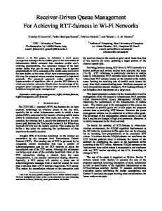
2. Networking device architecture A trend in high-speed networking system design until recently has been to offload higher layer protocol functions, that are not performed at wire speed to external system control processors in a centralized manner. High level protocol processing such as: routing, statistical compiling and reporting, error processing, connection admission control, network and transport layers protocol processing (e.g. ATM/AAL, TCP/IP, SSCOP) and traffic and/or resource management, often today, are treated as a system’s slow path. In order to accomplish the considerable processing power and memory throughput, required to execute protocol stacks for large numbers of connections, often more than one high performance processing units are employed. In such systems, the processing units are inadequate in supporting the protocol processing requirements for the entire set of active sessions. This constitutes a major system resource bottleneck, because the complexity of the protocol algorithms requires higher computational power than that offered by today’s processor technology. Moreover, new services, applications and provider’s requirements raise the significance of performing complex protocol processing tasks at ever increasing rates, since control and management plane functionality, as well as deep packet inspection and data transformation, are an integral part of modern telecommunication applications. In order to address those issues, we have designed the NPMADE which is an FPGA oriented Protocol Processor that provides the required processing power through a novel architecture incorporating parallelism and pipelining, wherever possible, by integrating both fixed hardware and generic micro-programmed engines with general-purpose processors. In particular, in the NPMADE, as shown in Fig. 1 there are dedicated units that perform the networkspecific processing (like packet classification, or packet buffering), and leave to the set of the general purpose processors, the higher level tasks of network processing. This has been proven to be a very efficient approach to protocol processing [11]. The basic data flow in NPMADE goes through the QMS, which, as it is described in Section 3, offers a flexible buffer layer for data buffering prior to processing and, more
A. Nikologiannis et al. / Microprocessors and Microsystems 28 (2004) 223–236
225
Fig. 1. The NPMADE Architecture.
importantly, per flow queue management. In general, the QMS offers a set of operations for flexible packet processing like: 1. Enqueue one segment of packet or a full packet 2. Delete one segment of a packet or a full packet from the head or the tail of a queue 3. Overwrite a segment 4. Append a segment at the head or tail of a packet 5. Move a packet to a new queue These functions allow for the basic packet forwarding operations; for example segmentation and reassembly, protocol encapsulation, header modification and multiple buffer management mechanisms. By supporting those operations, as shown in [13] we have managed to accelerate several real world network applications such as: † Ethernet switching (with QoS support e.g. 802.1p, 802.1q, etc) † ATM switching † IP over ATM internetworking † IP routing † Network Address Translation † PPP (and others) encapsulation Obviously the actual processing is done in the several RISC microprocessor cores (RISC in Fig. 1). One of the innovations of this reference system, which is analytically described in Section 3, is the way the QMS communicates with the several processing cores. We also claim that this communication mechanism will be very useful in cases where the QMS would be embedded in any multiprocessing system (and all the proposed Network Processors today are indeed multiprocessing machines).
The Connection Memory Manager performs the programmable header processing and respective table look-up functions for routing and packet classification. This is a very important task since the data buffering prior to classification relaxes the requirements for worst-case wirespeed operation of the classifier and make look-up schemes with reduced cost memory technologies feasible. The Scheduler module is an enhanced version of an existing design, able to support Weighted Fair Queueing and rate shaping for 32 K of queues for both cell and packet based traffic. The scheduling module is also responsible for the control of the memory access operations, initiated by the processing of the cells/packets. As it is clearly shown by the functional description of the NPMADE, the QMS is probably the most critical hardware module of the system, and within this protocol-processing device, the proposed management system is certainly stressed, since all the network packets/cell arriving or departing from the system should be processed by the QMS.
3. The queue management system (QMS) The main function of the QMS is to store the incoming traffic in certain individual queues to the data memory, retrieve parts of the stored packets and forward them to the CPUs for protocol processing. The QMS is also capable of receiving packet modification commands from the CPUs and to forward the stored traffic to the output, based on a programmable traffic-shaping pattern. The packet payloads accounting for the majority of the incoming traffic, are transferred twice to/from the data memory, one when entering the system and one when leaving it. Only a small portion of bits per packet (the packets’ headers) is transferred for processing and possibly for modification to
226
A. Nikologiannis et al. / Microprocessors and Microsystems 28 (2004) 223–236
Fig. 2. QMS Architecture.
the CPU. As it is shown in Section 3.1, the QMS allows stored packets to receive different levels of processing without keeping multiple copies of them in data memory. This minimizes the data throughput requirements in the FPGA and simplifies software in the CPUs. It performs per flow queuing for up to 32 K flows. The QMS operates both at fixed length or variable length data items. It uses DRAM for data storage and SRAM for segment and packet pointers. Thus, all manipulations of data structures (pointers) occur in parallel with data transfers, keeping DRAM accesses to a minimum. Fig. 2 outlines the architecture of the QMS. It consists of five main blocks: Data Queue Manager (DQM), Data Memory Controller (DMC), Internal Scheduler, Segmentation Block and Reassembly Block. Each block is internally pipelined in order to exploit parallelism and increase performance. In order to achieve efficient memory management in hardware, the incoming data items are partitioned into fixed size segments of 64 bytes each. Then, the segmented packets are stored in the data memory, which is segment aligned. The internal scheduler forwards the incoming commands from the various ports to the DQM giving different service priorities to each port. The DQM organizes the incoming packets into queues. It handles and updates the data structures, kept in the Pointer memory. The DMC performs the low level read and writes to the data memory minimizing bank conflicts in order to maximize DRAM throughput. The In/Out and the CPU interfaces have the capacity to connect to multiple physical network interfaces and to a large number of CPU cores, as the following Section 4 describes.
The QMS provides a large instruction set in order to support the diverse protocol processing requirements of any device handling queues. Beyond the primitive commands of ‘enqueue’ and ‘dequeue’, the QMS features a large set of twelve commands to perform various manipulations on its data structures (a list of all the commands is given in Table 1). Thus, it can be incorporated in any networking embedded system that can handle queues. 3.1. Memory technology A critical decision for the QMS architecture was the choice of the memory technology. Due to the complexity of the supported operations, the data structures are located in Table 1 Latency of QMS’ commands Simple commands
Clock Cycles
Pointer memory accesses r:Read w:Write
Enqueue Read Overwrite Append
10 10 10 11
Delete Overwrite_Segment_length Dequeue
7 7 11
Overwrite_Segment_length and Append Overwrite_Segment and Append
12
4r4w 3r 3r Min 5 (3r2w) Max 8 (3r5w) 2r1w 2r1w Min 5 (3r2w) Max 8 (3r5w) 6r4w
12
6r3w
A. Nikologiannis et al. / Microprocessors and Microsystems 28 (2004) 223–236
227
Fig. 3. The QMS data structures.
a different memory (control memory), from packets (data memory). DRAM is selected for data memory because it provides large storage space and comparable throughput to SRAM, at a much lower cost. We chose DDR-DRAM for the data memory because it provides adequate throughput for supporting the operations of the NPMADE network processor. A modern DDR-SDRAM module provides 25.6 Gbps total throughput over a 64-bit wide data bus operating at 200 MHz. However, the large number of the pointer memory accesses that are required raises the need of a high throughput - low latency memory. We use SRAM for pointer memory, which has the capacity to provide the required performance. Modern SRAMs working at 200 MHz clock frequency provide 200 Million accesses per second or about 12.8 Gbps (assuming 64 bit data bus). 3.2. Data structures and queue organization We organize our data memory space into fixed-size buffers (named ‘segments’). We chose 64-byte segments because this size minimizes fragmentation loss as it is proved in [18]. For each segment, in the data memory, a segment pointer and a packet pointer are assigned. As shown in Fig. 3, the addresses of the data segments and the corresponding pointers (Segment and Packet Pointers), are aligned, in the sense that a data segment is indexed by the same address as their two corresponding pointers. For example, the packet and segment pointers of the segment 0 are in the address 0 in the pointer memory. The data queues are maintained as single-linked lists of segments. Head and Tail pointers are also required for each individual queue; the head pointer points to the first segment of the head packet in the queue while the tail pointer indicates the first segment of the tail packet. Those Heads and Tails are stored in the Queue Table shown in Fig. 3, which has 32 K entries, since this is the maximum number of queues the system can support. Usually, single linked lists are accessed from head to tail; however, our linked list organization allows
also deleting a packet from the tail of a queue for the last inserted packet1. This is achieved by keeping the start address of the last packet in the segment pointer of the last segment of the queue (which is usually null). The QMS can handle variable length objects (called packets) as well as fixed-size data items. This is achieved by using two linked lists per flow: one per segment and one per packet. Each entry in the segment level list stores the pointer that indicates the next entry in this segment list. The maximum number of entries in a data queue is equal to the maximum number of segments the data memory supports. The packet pointer field has the valid bit set only in the specific entry that corresponds to the first segment of a packet. The packet pointer also indicates the address of the last segment of a packet. The number of entries of the packet list is lower than the number of entries of the corresponding segment list in a typical situation. However, in the worst case, the maximum number of entries in the packet list is equal to the number of segment list, which in term is equal to the maximum number of the supported segments in the data memory. Since we support two types of queues (packet, segment) we need two free lists, one per type. This results in double accesses for allocating and releasing pointers. We use flexible data structures, which minimize memory accesses and can support the worst-case scenarios [18]. The two types of linked lists are identical and aligned. In other words, there is only one linked list with two fields: segment and packet pointers. 3.3. QMS organization The DQM block is divided in two sub-blocks: DQM_CPLX_CORE and DQM_CORE, as shown in Fig. 4. The DQM_CPLX_CORE block may receive both complex and simple commands from the various interfaces 1 This function is very useful when receiving networking packets with wrong error redundancy code or in general, a destroyed network packet.
228
A. Nikologiannis et al. / Microprocessors and Microsystems 28 (2004) 223–236
Fig. 4. DQM Architecture.
but sends only simple commands to the DQM_CORE block. In addition this block serializes and arbitrates incoming commands from the various ports in a round robin order. The DQM_CORE block executes only simple commands and updates data structures by accessing the external pointer memory, as shown in Fig. 4. The micro-architecture of the DQM_CPLX_CORE is shown in Fig. 5. Complex commands are kept in FIFOs. As soon as a command reaches the head of the FIFO, a check is performed so as to realize whether there is a complex or a simple instruction. If it is a simple one, it is eligible for execution and thus it is forwarded to the arbiter and a new command from the FIFO is dequeued and checked. If it is a complex command, the FSM generates as many simple commands as required and forwards them for execution to the arbiter. In this case (complex command) a new command is dequeued from the FIFO only if the previous
complex command has completed its execution. The arbiter services the waiting simple commands (one per port) in a round robin order. The arbiter also receives backpressure signals from the reassembly block to suspend command service from a port if the CPU that generates these commands is busy and cannot process them immediately. This avoids data congestion to the reassembly block, gives priority to the other ports and therefore uses QMS resources more effectively. Note that the arbiter does not prioritize the multiple interfaces in the common case (i.e. on backpressure signal is asserted) because this is the responsibility of the internal scheduler as shown in Fig. 2. The QM_CORE block is the heart of the QMS. It consists of a Register File, a Configuration Register File and a large FSM. The Register File keeps critical values that FSM reads and writes. The Configuration Register File consists of control registers that are set during the initialization phase and define the QMS’ behavior. The large FSM consists of ten states and supports twelve operations. This sub-block is not pipelined because there is no parallelism in the use of pointer memory. Note that each command execution consists of many accesses to pointer memory (approximately eight in average case as Section 4 demonstrates). Some of them are intra-dependent which obviously cause undesirable delays in the overall command execution. Dependencies are reduced and even eliminated by using memory access reordering; reordering handles memory dependencies in an efficient manner and maximizes the memory throughput utilization. The micro-architecture of the data memory controller is shown in Fig. 4. The Data Memory Controller (DMC) block sends read and write commands to the data memory. It has
Fig. 5. DQM_complex core micro-architecture.
A. Nikologiannis et al. / Microprocessors and Microsystems 28 (2004) 223–236
229
Fig. 6. Data Memory Controller micro-architecture.
two types of interfaces: data and command interfaces. The data memory can at most execute one command per four memory clock cycles2. However, successive dependent accesses to the data memory may cause bank conflicts, which increase the execution time of a command (thus reducing overall throughput). The DMC effectively handles bank conflicts by keeping the recent history of memory accesses and scheduling pending commands for execution according to this history. The DMC organizes the incoming commands per port, by keeping them in one separate FIFO per port (Four port in the example of Fig. 6); in this way it avoids the head of line blocking3 and handles the commands more effectively. It serves commands from the various FIFOs in a round-robin manner. If a command FIFO is blocked, the DMC does not serve it but, instead, it serves a command from one of the other FIFOs (it is even possible to service more than one successive commands from the same command FIFO, if the all the other FIFOs are empty/blocked). If all the command FIFOs are blocked or they are empty, then it asserts a no-operation (‘deselect access’) to the data memory for execution. The DMC service architecture is simple to implement, flexible and maximizes data memory throughput utilization, as Section 4 clearly demonstrates.
2 Write or read a 64-byte segment to a data memory of 64-bit data bus and using the double-rate feature requires 4 memory cycles. 3 In case of using a single FIFO: if the head command from port 1 is going to access a busy bank and the following commands from other ports are going to access non-busy banks, they have to sustain the delay until the busy bank becomes available for accessing.
3.4. Supported operations QMS supports a great number of operations specified to simplify and accelerate the execution of real world network applications in the CPUs. Apart from enqueue and dequeue, QMS supports read and overwrite operations, in order to be able to process and modify a packet by retrieving only a small copy of the stored packet (packet header). A stored packet can receive multiple levels of processing from different CPUs without having to copy it multiple times in data memory. This can be achieved by using the Append Packet operation, which dequeues a whole packet from a level-1 processing flow and enqueues it to a level-2 processing flow without move the packet body; it only modifies packet pointers kept in pointer memory. 3.5. Optimization techniques The following Sections 3.5.1 –3.5.4 describe, in detail, the optimization techniques employed in the QMS so as to increase its performance, while at the same time keep the cost of the system at a low level. 3.5.1. Free list organization The DRAM provides high throughput and capacity at the cost of high latency and throughput fluctuations due to bank conflicts. A bank conflict occurs when successive accesses address the same memory bank, and in such case the second access must be delayed until the bank is available. Hence, special care must be given to the buffer allocation and deallocation process. In [18] it is proved that by using a single free list someone can minimize the memory accesses
230
A. Nikologiannis et al. / Microprocessors and Microsystems 28 (2004) 223–236
for buffer releasing (i.e. delete or dequeue of a large size packet requires O(1) accesses to the pointer memory). However, this scheme increases the possibility of a bank conflict during an enqueue operation. On the other hand, using one free list per memory bank (total eight banks in the current DRAM chips) minimizes or even avoids bank conflicts during enqueueing but increases the number of memory accesses during packet dequeueing-deletion to O(N)4. A trade off of these two schemes, which minimize the memory accesses and bank conflicts is to use two identical free lists, one holding the segment addresses of the first four consecutive banks, while the other one the segment addresses of the next four ones. Additionally, the support of page-based addresses on the DRAM results in reduction of up to 70% in the number of bank conflicts during writes and 46% during reads, as shown in [5]. 3.5.2. Memory access reordering The execution of an incoming command, such as Enqueue, Dequeue, Delete or Append packet, sends read and write commands to the pointer memory in order to update the corresponding data structures. Due to access dependencies, the latency when executing an operation may be increased. By reordering the accesses in an effective manner the execution latency is minimized and thus the system performance increased. This reordering is performed for every operation and we measured that it achieves a 30% reduction in the mean access latency. 3.5.3. Memory access arbitration Using the described free list organization we control the write accesses to the data memory in order to minimize the bank conflicts. An analogous control cannot be performed in read accesses because they are random and unpredictable. Thus, a special memory access arbiter is used in the data memory controller block to shape the flow of read accesses in order to avoid bank conflicts. Memory accesses are classified in four FIFOs (one FIFO per port). The arbiter implements a round-robin policy. It selects an access only if it belongs to a non-busy bank. The information for bank availability is achieved by keeping the data memory access history (it remembers the last three accesses). This function minimizes bank conflicts by 23% as the results of our experiments show. It also reduces the hardware complexity of the DDR memory controller.
Internal backpressure avoids overflows and data loss so as to increase the reliability of our architecture.
4. Implementation and performance evaluation The architecture of the NPMADE has been implemented in a Virtex II Pro Platform FPGA [17]. This programmable logic device offers high performance and high density. Both of these features of the reconfigurable logic have been exploited in the implementation of this design, as is described in the next subsections. The IBM PowerPC 405 [7] embedded processor has been used as the control processor and the MicroBlazes as the data processing CPUs of Fig. 1. The Processor Local Bus (PLB) provides the primary mean of data flow between the PowerPC, the QMS and the IPSec, the On-Chip Peripher Bus (OPB) and a custom bus is used for the communication of the QMS with the Microblazes and the Xilinx’s Device Control Register (DCR) is used as the control bus. The QMS can be directly attached to the PLB and the DCR standard busses, thus it can be easily used as an IP core in any design that uses the CoreConnect Architecture, or as a separate FPGA based co-processor that communicates with the main network processor using a CoreConnect off-chip bus. Obviously, if a different interconnection bus is employed for the communication of the QMS with an NP (either on-chip or off-chip), the only addition needed is a simple module implementing the ‘glue logic’ that will transform the CoreConnect bus to the NP’s interconnection one. 4.1. QMS-CPU interface The Scheduler (TSC) is responsible to trigger the QMS, which in turn will retrieve the segments from the off-chip packet memory and send them to one of the CPUs; the appropriate processing unit is indicated in the destination field in the TSC’s command. Fig. 7 shows
3.5.4. Internal backpressure The data memory manager uses internal backpressure in order to delay incoming operations that correspond to blocked flows or blocked devices. The QMS keeps data FIFOs per output port. As soon as these FIFOs are about to overflow, backpressure signals are asserted in order to suspend the flow of incoming operations related to this blocked datapath. 4
N is the number of segments per packet.
Fig. 7. The OPB, PLB and BRAM Bus.
A. Nikologiannis et al. / Microprocessors and Microsystems 28 (2004) 223–236
the interconnection scheme adopted in the NPMADE architecture involving the mentioned components. The main drawback of the Microblaze processor used is that it does not support the burst mode of OPB [15,16]. In order to avoid the OPB being the bottleneck of the design, a simpler but more efficient bus has been used so as to transfer data between the QMS and the Microblazes. This bus is connected with one port of a dual-port BRAM using a BRAM controller, while the other port is attached to the LMB port of the Microblaze. The main advantage of the dual port BRAM is that it supports asymmetric port configurations. The data port A, which it is attached to the LMB controller is 32-bit wide, while the data port B, which is attached to the QMS is 64-bit wide. Using this bus we can transfer a 64-byte segment in only eight cycles. The BRAM controller has two modes. In the first mode the QMS sends only the initial address where the 64-byte segment should be stored and the BRAM controller calculates the next seven addresses, while in the second mode the QMS defines the addresses of every single word. The detailed communication protocol is described in Section 4.1.1. The OPB is mainly used to transfer commands from the Microblazes to the QMS, while the QMS has also a PLB interface, in order to be able to transfer segments over a high throughput interconnection bus in case an application requires IPSec or exception processing for example (handled by either the IPSec Co-processor or the PowerPC Control CPU). The current architecture can utilize up to eight Microblazes, and since it is a highly modular design tailored to reconfigurable logic anyone can easily configure it to support from one to eight different CPUs. 4.1.1. Polling-driven communication When the QMS has a segment to transfer, it writes it to a Microblaze’s BRAM and sets a semaphore. When the Microblaze has no other work to do, it polls that semaphore. When it finds it set, it sends an acknowledge command through the OPB to the QMS, providing also the address of the next input buffer, then it clears the semaphore and starts processing the packet. The QMS always waits for the acknowledgment before sending the next segment to a certain Microblaze. For the processing of a single packet, the QMS may need to transfer one or more segments to the CPU, while the CPU itself may transfer zero (e.g. for ‘delete packet’) or more segments to the QMS. Because of packet discard, encapsulation, and de-capsulation, the number of segments transferred in each direction can be different. In general, three different semaphores are used: 1. Write semaphore: set by the BRAM controller when a segment is transferred by the QMS to the CPU, and reset by the CPU when the it starts processing a segment. 2. More semaphore: set by the BRAM controller when a segment is transferred by the QMS to the Microblaze
231
upon a more request. The CPU resets it when the it starts processing this segment. 3. Poll semaphore: Set by the Microblaze when a segment is placed in the BRAM after its processing has been finished and therefore the QMS has to read it. The BRAM controller resets it when the last byte has been transferred to the QMS. 4.1.2. Communication protocol The communication protocol between the QMS and the CPUs consists mainly of the following operations. † Upon receiving a command from the TSC the QMS decodes the destination CPU, retrieves the segment from the external packet memory, transfers it to the local BRAM of the Microblaze at a specified address (Saddri) and sets the write semaphore. † The CPU clears the semaphore, sends an ACK command to the QMS along with a new address for the next segment and starts processing the current segment. † The QMS after receiving the ACK command, if a new instruction has been received from the TSC it may send again another segment and set the new buffer’s semaphore. † When the Microblaze finishes the processing of one segment it places the result (one or more segments) in a BRAM free location, sets the poll semaphore, and sends an appropriate command to the QMS (‘enqueue_segment’, ‘overwrite_segment’, etc.) along with the address (Oaddri) from where the QMS can retrieve it. † After the QMS retrieves this processed segment it clears the output buffer semaphore so as to indicate that the processed segment is retrieved successfully. In the meantime the QMS may have sent another segment to the same Microblaze. † This same Microblaze may process the next segment but at the same time must poll the output buffer semaphore, before sending to the QMS the next address specifying where the new result is located. † A certain CPU may need to process other additional segments of a packet besides the first one that the QMS has placed in the BRAM. In this case this certain Microblaze writes the corresponding command designating to the scheduler at a specific address of the BRAM and then a ‘more’ command, associated with the corresponding address (Maddri) is sent to the QMS through the OPB bus. The QMS first reads the scheduler command from the BRAM and after retrieving the requested segment and writing it to the BRAM, it sets the more semaphore. Hence, this certain Microblaze must poll the flag at the Maddri to check when the QMS has completed the operation requested with the ‘more’ command. In order to implement this protocol, the Microblaze needs two input buffers, two output buffers, and one ‘more’ buffer;
232
A. Nikologiannis et al. / Microprocessors and Microsystems 28 (2004) 223–236
all of them are just movable portion of its cache (BRAM). Two input buffers are needed to allow the QMS to transfer the next segment, when at the same time a Microblaze is processing the previously sent segment. Two output buffers are needed since the QMS could be busy and may not be able to immediately read out the processed packet. By having two output buffers, the Microblaze can start processing the next packet, before the QMS reads out the previously processed segment. In general, we need a total of five buffers, 72 bytes each, or 360 bytes total, in each BRAM so as to be able to support efficiently this communication mechanism. Due to different tasks/packet processing performed in the CPUs the segments read from the external packet memory are buffered and then are forwarded to the appropriate Microblaze in a round-robin fashion. The segment fetched upon a ‘more’ request has absolute priority against another destined to this same Microblaze. 4.1.3. Interface’s performance The main advantage of this protocol is that it parallelizes the I/O operations with the actual packet processing, and therefore we have managed to completely hide the latency of the I/O operations. As it has been shown in [13], this latency is a significant part of the total packet processing time in all the existing architectures, and therefore by completely hiding it, we can achieve a substantial acceleration of the network processing. Moving to the performance of our interconnection scheme, we have compared it with the actual performance of the OPB bus. According to the OPB specifications [15] the peak data rate of the bus is 500 Mb/s, while the typical performance is only 167 Mb/s assuming three clock cycles per OPB transfer and 125 MHz clock rate. On the other hand, Xilinx’s LMB bus supports 500 Mb/s peak data rate and 333 Mb/s typical data rate (assuming 66.7% utilization).
Apparently, using the typical Xilinx interconnection buses, we need at least 5 cycles so as to read a single word from the OPB bus and write it to the Data BRAM of the Microblaze, Therefore, the maximum bandwidth that can be sustained, when this typical scheme is employed, is in the order of 100 Mb/s only! Using our custom bus, which connects the one port of the BRAM with the QMS, we can overcome this bottleneck. The peak performance of this bus is 800 Mb/s using 100 Mhz clock rate. Assuming that one cycle per segment transfer (one cycle for the control word and eight cycles for data) is used for signaling (polling) the utilization is 90%, which means 720 Mb/s actual performance, or in other words more that seven times the performance of Xilinx’s interconnection scheme. 4.2. PLB and DCR interfaces The communication protocol between the QMS and PLB is depicted in Fig. 8. A PLB slave interface has been developed that can support burst and line transfers (the QMS is configured as a PLB slave). The address range of QMS is separated in two sections. The first section supports write transactions only and is used to transfer QMS commands from the PowerPC to the QMS, while the second section is used to transfer data and supports both read and write transactions. The commands from the first sections are stored in the ‘command FIFO’ while the ‘write data FIFO’ and ‘read data FIFO’ are used for write and read transactions respectively. The QMS generates an interrupt to the PowerPC whenever the PowerPC must handle some exception packets. A Device Control Register (DCR) Interface has also been incorporated in the QMS module. This interface is used to access the control registers of the QMS such as the initial Head and Tail pointers of FreeList. The PowerPC processor
Fig. 8. The QMS-CPU-Bus Interface.
A. Nikologiannis et al. / Microprocessors and Microsystems 28 (2004) 223–236
is the DCR Master, which configures and monitors the QM system via these registers. 4.3. Network interfaces One additional advantage of the FPGA-tailored QMS module is that it can easily be configured so as to communicate with various physical ports i.e. 10/100 MAC, 1 Gbit MAC, ATM ALL5 or a POS module. The network ports use a simple, well-defined interface to communicate with the QMS. In the receive path the packets are segmented by the network interface module and are sent to QMS. Each segment is preceded by a header, which contains information about the segment length, the packet identification number, etc. The network port sets the ‘segment available’ signal and as soon as the QMS can handle it, it initiates the segment transfer. A similar interface is used in the transmit path; the QMS is the Master also in this path, that samples the ‘available’ indications of the physical ports and serves the output traffic in a round-robin manner. In the current NPMADE design one ATM, one POS-PHY L2 module, and two 10/100 Mbits Ethernet MACs are all connected to the QMS. 4.4. QMS resilience The QMS design is so flexible, as already demonstrated, that it allows interdisciplinary treatment of all command ports. This architectural option, although it inserts little complexity, is deemed essential, since it enables the system designer to attach a differentiated module (hardware or software component) to one of these ports. The current Scheduler (TSC) in our network platform implements two scheduling policies and although it is programmable enough, it does not have the flexibility of a process residing in one RISC-CPU and being responsible to schedule a set of flows according to complex criteria. Thus, and due to the flexibility of the proposed architecture, we can easily adopt a different scheduling policy, at no additional cost while we can also bypass/eliminate the TSC hardware module in case of malfunctioning, or in case the silicon area is considered indispensable for other more critical components. 4.5. System performance In order to analyze the performance of the QMS, we first check the possible bottlenecks of our architecture. In general, these bottlenecks can be either due to the memories themselves (DRAM, SRAM) or due to the hardware complexity of the implemented logic. We first do a quantitative analysis of the QMS performance and then we present experiment results that prove that our analysis holds when the QMS executes real world applications. Let’s assume that the bandwidth coming from all the input ports sums to about 5 Gbps.
233
The total required incoming throughput to the data memory is the actual input traffic from the various ports plus the throughput loss due to the memory fragmentation and the bank conflicts. Given the analysis in [5] the fragmentation losses are about 20% each, so the total bandwidth needed from the DRAM should be about 7 Gbps. All the traffic coming in the data memory should at some point come out of it; thus the total required throughput of this memory is 14 Gbps. Using a DDR-SDRAM clocking at 133 MHz provides 17 Gbps total throughput, which is sufficient for the NPMADE requirements. Deducing the above consideration, data memory does not seem to be bottleneck in the system, because modern DDR-SDRAMs can operate at higher clock rates (200 MHz). Regarding the pointer memory, the memory manager must be able to service one command per port per time slot. Assuming an average number of required accesses to the pointer memory of six per command plus four idle cycles due to access dependencies, the execution of a command requires ten memory cycles. Executing four commands (four ports) in a time slot5 requires 195 Million accesses per second. Modern ZBT-SRAMs working at 200 MHz provide 200 Million accesses per second; thus, pointer memory also meets our system requirements. Finally, regarding the actual operational speed of the system, the QMS core should work at a speed of 200 MHz (as shown in [5]) in order to be able to support a total of 10 Gbps of actual throughput. Unfortunately, as Section 4.6 demonstrates, the QMS cannot work at more than 125 MHz in todays’ FPGA technologies, therefore the bottleneck of the design is certainly the FPGA implementation of the QMS core. 4.6. Experiment results Extensive experiments of the QMS were performed with the support of micro-code specifically developed for the embedded CPUs of the network platform. Table 1 shows the measured latency of simple-segment commands and the number of necessary pointers’ manipulation functions. The actual data accesses at the Data Memory can be done, almost, in parallel with the pointer handling. In particular, a data access can start after the first pointer memory access of each command has been completed. This is achieved because the pointer memory accesses, of each command, have been scheduled so as the first one provides the Data memory address. The QMS latency has also been measured for a system that has a conservative clock of 125 MHz. Table 2 shows the QMS average latency for different loads. The total latency consists of three parts: the FIFO, the execution and the data latency. QMS keeps incoming commands in FIFOs 5
The time slot is defined as the time that is required to receive or send a 64-byte segment from/to the network at 2.5 Gb/s line rate and thus it is equal to 204.8 ns.
234
A. Nikologiannis et al. / Microprocessors and Microsystems 28 (2004) 223–236
Table 2 QMS Delays Overall load (Gbps)
Fifo delay
Execution delay
Data delay
Total
31.3 30.8 30 29.1 28
109.8 98.3 60.5 59.6 58.5
Clock cycles (125 MHz clock) 6.14 4.8 4 3.2 1.6
68 57 20 20 20
10.5 10.5 10.5 10.5 10.5
(one per port) so as to smooth the bursts of commands that may arrive to the system. The latency that a command suffers until it reaches the head of the FIFO is the FIFO latency. As soon as a command reaches the head of the FIFO it starts its execution by accessing the pointer memory. The latency introduced from this point until the execution if complete is the execution latency. Finally, the delay required to write or read a data segment along with the possible bank conflict delay is called the data latency. The execution delay defines the time interval between two successive commands starting their execution; in other words it states the QMS process rate. Experimental results show that an operation requires an average delay of ten memory cycles. The QMS can handle one operation per 84 ns or 12 Mops/s operating at 125 MHz. In other words, and since each operation is executed on 64-byte segments, the overall bandwidth the QMS can service is 6.145 Gbps. 4.7. Performance Comparison In order to demonstrate the efficiency of the QMS, we have also simulated the memory management functions is software using various system configurations. We believe that those results are very important since in the vast majority of the existing network processors (NPs), the memory management is done in software. For those experiments we have used two different microprocessors: Xilinx’s Microblaze and IBM’s high end
PowerPC. The first one is a simple RISC engine, similar to the ones found in the NPs of Intel (IXP-2xxx [6]), IBM (PowerNP [1]) and Cisco (Toaster [2]), while the second is a very sophisticated RISC microprocessor widely used in high-end network systems and similar to the very sophisticated one used by Alpha in [10]. In Fig. 9 the throughput achieved, when the memory management functions are executed in different systems, is shown. The software results were collected by running the QMS-equivalent optimized assembly code in real systems implemented in a Virtex-II Pro FPGA. In particular, the Microblaze was synthesized and implemented into the FPGA, together with a standard 100 MHz Xilinx’s OPB bus. Similarly, the built-in PowerPC of the Virtex-II Pro is clocked at 200 and 400 MHz in the two experiments, and in both of them it is connected to a standard Xilinx’s PLB 100 or 200 MHz bus. It should also be noted that in all those cases the actual DRAM and SRAM controllers are exactly the same with the QMS’ ones and that the delay overhead of the various processor interrupts is ignored. In the PowerPC the delay overhead of an interrupt is about 5 ms for the interrupt initialization and 1.5 ms for the interrupt termination. As those results clearly demonstrate the QMS has about ten times the throughput of that of the 400 MHz PowerPC when execute the most commonly used queue management commands. In particular, the Microblaze can service at most 100 Mbps of network traffic, while the 400 MHz PowerPC, with the 64-bit 200 MHz PLB bus, about 600 Mbps. In between the two, the 200 MHz PowerPC, when connected to a 64-bit 100 MHz PLB bus, can service about 400 Mbps of network traffic. The low performance of the software approaches comes mainly from the fact that the pointer manipulation functions are very memory intensive, while also the data and pointer transfers over the processor busses consume a large number of clock cycles. Moreover, the QMS is less than 40% slower than the DMM, which is probably the only known ASIC implementation of a fully featured multi-Gigabit, stand-alone memory
Fig. 9. Memory management performance.
A. Nikologiannis et al. / Microprocessors and Microsystems 28 (2004) 223–236
235
Table 3 Complexity of QMS submodules Module
Max frequency (MHz)
Slices
Slice Flip–Flops
Block RAMS
4 input LUTs
DMC DQM core DQM Complex QMS-Network I/Fs QMS-SRAM I/F QMS-CPU I/Fs DDR-Controller QMS
124.3 133 192 149 223 127 137 124.3
1200 1200 700 2200 570 2100 500 8500
1500 900 1000 2900 600 1600 730 9500
3 0 8 23 6 32 0 73
2135 2300 950 4370 1000 3400 370 14000
management system. The DMM is implemented in the state-of-the-art memory technology and it is clocked at 200 MHz. 4.8. Hardware Implementation Table 3 summarizes the Xilinx XST placement and routing results, for a Virtex-II Pro device. The implemented system has four network interfaces and two CPU ones. The QMS system is broken down to its major components, in an effort to locate the critical parts both in terms of area and timing. As those results, clearly demonstrate, the most complicated parts are not only the actual processing cores of the system, but also the various Interfaces. This is mainly because all those interfaces contain a significant number of FIFOs for temporary buffering and synchronization purposes. Note that those FIFOs should be quite large, since the QMS services just one request at a time, and both the network and CPU interfaces are totally asynchronous and therefore, there maybe a case where all of them request for a different QMS operation at the same time. Hence, an arbitration mechanism is also implemented inside these subblocks. As it was described in Section 1, the QMS is the successor of the DMM, which has been implemented in an ASIC technology. Since one of the main reasons that we have designed and implemented the QMS was the high complexity of the DMM, we have also measured the implementation characteristics of the latter. According to the Xilinx tools, the DMM needs more than 11,000 slices and it can operate at most at about 110 Mhz (107 Mhz). Therefore, we claim that by re-designing this Memory Management system and optimizing it for hardware density and for FPGA implementation we managed to have a design, which was both faster and smaller. In particular, in order to take advantage of the special characteristics of the FPGA, we have used only positive edged flip-flops (whereas the DMM uses both positive and negative for optimizing the performance), and more importantly, we split our logic and we chose the optimal FSM coding so as to make sure that the combinational logic of the various FSM states was able to fit in the Slices that were containing the corresponding state Flip-Flops (or at least in the ones that
were close by). Also, we have altered the size of the various FIFOs so as to perfectly match the Block RAMs of Xilinx. Finally, and in order to achieve the 125 MHz clock mentioned, we have heavily hand-crafted the, produced by the tools, Placement and Routing of the various submodules/cells/nets. In general, we claim that the QMS can efficiently be implemented in 8500 slices of an FPGA, either as an on-chip module in an existing FPGA-based NP, or as an NP co-processor, providing more than 6 Gbps of real queue Management bandwidth.
5. Conclusions This paper describes the QMS, which is an FPGA-based Queue Management system that provides fully programmable and ultra high-speed manipulation of tens of thousands of data queues. The QMS has, so far, been integrated in a prototype network embedded system, called NPMADE, so as to evaluate its performance in a real networking device. Based on the results within NPMADE, we support that this system can effectively be used in any networking system that handles large numbers of queues, and will significantly increase its overall performance. In general, it is a very useful component for every networking system that manipulates queues since: a) it supports a large number of simple request-acknowledge interfaces, b) it executes a large number of general instructions and c) it can handle either fixed size or variable length pieces of data. In particular, we believe that this system will be a valuable add-in for both the newly emerged FPGA-based NPs, that have no special queue management units (in which case it will be incorporated in the same FPGA as the NP), and, as a co-processor in a separate FPGA, for the commercial ASIC NPs that have no dedicated memory handling software. The QMS provides an aggregate throughput of 6.2 Gbps using a DDR-DRAM memory device and a typical SRAM one, while supporting 32 K different queues. We have also compared the QMS with the software approach which is widely used in today’s Network Processors and we claim that even a state-of-the-art microprocessor is used
236
A. Nikologiannis et al. / Microprocessors and Microsystems 28 (2004) 223–236
the maximum throughput achieved by a software mechanism is in the order of 600 – 700 Mbps. Moreover, when comparing it with a similar ASIC implementation in a state-of-the-art CMOS technology, the QMS is less than 40% slower. Other advantages of the QMS are that a) its latency is about the same with that of a simple DRAM controller and b) its hardware complexity is only about 8500 slices of a state-of-the-art FPGA.
References [1] A. Franc¸ois, C. Minkenberg, R.P. Luijten, M. Gusat, I. Iliadis, A FourTerabit Packet Switch Supporting Long Round-Trip Times, IEEE Micro. 23 (1) (2003) 32 –39. [2] Cisco Corporation, Cisco’s Toaster 2 Chip Receives the Microprocessor Report Analyst’s Choice 2001, Award for Best Network Processor, http://www.cisco.com, January 2002. [3] J. Jessen, A. Dhir, Programmable Network Processor Platform, Xilinx Corporation, White Paper http://www.xilinx.com/esp/ networks_telecom/optical/collateral/ip_semi_case_study.pdf, January 2003. [4] L. Geppert, The new chips on the block, IEEE Spectrum 38 (1) (2001) 66–70. [5] G. Kornaros, I. Papaefstathiou, A. Nikologiannis, N. Zervos, A FullyProgrammable Memory Management System Optimizing Queue Handling at Multi Gigabit rates, 40th IEEE/ACM Design Automation Conference (40th DAC), June 2 –6, Anaheim, California, USA, 2003. [6] L. Sridhar, et al., The next generation of Intel IXP network processors, Intel Technol. J. (2002). [7] R. Mateosian, The power PC in perspective, IEEE Micro. 14 (8) (1994) 32–45.
[8] M. Gokhan, S. Ogrenci Memik, W.H. Mangione-Smith, Design and Analysis of a Layer Seven Network Processor Accelerator Using Reconfigurable Logic, 10th Annual IEEE Symposium on FieldProgrammable Custom Computing Machines (FCCM’02), Napa, California, USA, 2002, pp. 23 –24. [9] T. Mohsenin, FPGA-Based Gigabit Ethernet Network Interface Card, Rice university, Technical Report, November 2003. [10] S. Mukherjee, P. Bannon, S. Lang, A. Spink, D. Webb, The alpha 21364 network architecture, IEEE Micro 22 (1) (2002) 26 –35. [11] N. Nikolaou, J. Sanchez, T. Orphanoudakis, D. Polatos, N. Zervos, Application Decomposition for High-Speed Network Processing Platforms, Second European Conference on Universal Multiservice Networks, ECUMN’, April 8–10, Colmar (2002) 8–10. [12] B. Suter, T.V. Lakshman, D. Stiliadis, A.K. Choudhury, Buffer Management Schemes for Supporting TCP in Gigabit Routers with Per-Flow Queueing, IEEE J Selected Areas Commun 17 (7) (1999) 39– 47. [13] K. Vlachos, T. Orphanoudakis, N. Nikolaou, G. Kornaros, K. Pramataris, S. Perissakis, J-A. Sanchez, G. Konstantoulakis, Processing and scheduling components in an innovative network processor architecture, Proceedings of the 16th VLSI Conference, New Delhi, India, January 4–8 (2003). [14] D. Whelihan, H. Schmit, Memory optimization in single chip network switch fabric, Design Automation Conference (39th DAC), June 10– 14, New Orleans, Louisiana, USA, 2002. [15] Xilinx Corporation, On-Chip Peripheral Bus, Architecture Specifications, Version 2.1, October 2002 [16] Xilinx Corporation, MicroBlaze Processor Reference Guide, November 2002. [17] Xilinx Corporation, Virtex II-Pro Data Sheet, September 2002. [18] Ykman ch, et al., System-level performance optimization of the data queueing memory management in high-speed network processors, Proceedings of the 39th Conference on Design automation (39th DAC), June 10 –14, New Orleans, Louisiana, USA, 2002.