AbstractâAn FPGA controller which can establish low-latency deterministic 'Guaranteed-Rate' (GR) transport connections for cloud services is explored.
An FPGA Controller for Deterministic Guaranteed-Rate Optical Packet Switching Ted H. Szymanski
Maryam Rezaee
Dept. ECE, McMaster University, Hamilton, Ontario, Canada
Dept. ECE, McMaster University, Hamilton, Ontario, Canada
Abstract—An FPGA controller which can establish low-latency deterministic ’Guaranteed-Rate’ (GR) transport connections for cloud services is explored. An SDN control-plane can create deterministic GR connections in a forwarding-plane of electrical or optical packet switches, where end-to-end delays are reduced to the fiber latency. A testbed for the proposed deterministic GR technology is presented. A forwarding-plane consisting of 8 controllers and minimum-complexity packet-switches are synthesized on an Altera Cyclone IV FPGA. An SDN control plane routes 128 traffic flows through the forwarding plane, which saturate the packet-switches. Several deterministic schedules are precomputed and loaded into the controller lookup tables, which control each packet-switch for each time-slot in a scheduling frame. The FPGA testbed is clocked at 52 MHz, allowing millions of packet transfers per second, and statistics are recorded. The testbed confirms the establishment of deterministic GR transport connections configured on a programmable underlay network, where the end-to-end delays are effectively reduced to the fiber latency. An inexpensive FPGA controller can add deterministic GR services to IP routers, MPLS, Ethernet, InfiniBand and Fibre channel switches, and layer-2 electrical or optical packet-switches, spanning 100s of nodes over distances of 1000s of miles. By using existing Silicon-Photonics technology, an SDN control-plane can manage deterministic GR connections in a programmable underlay network of integrated single-chip Optoelectronic Packet Switches, with aggregate capacities in the 100s of Terabits/sec. Index Terms—Deterministic Internet, low latency, software defined networks, control plane, forwarding plane, optical packet switching, guaranteed-rate
I. I NTRODUCTION Optical Packet Switching (OPS) is viewed as an attractive long-term technology to support the growing bandwidth demands of the Internet network. However, there are several challenges to OPS, including (i) the difficulty to perform large amounts of optical logic operations for packet header processing, (ii) the difficulty to perform very low-latency real-time contention-resolution, flow-control, and congestioncontrol in the optical domain, and (iii) the difficulty to buffer the large amounts of optical data associated with an IP router. Current IP routers typically have buffers for about 250 millisec of data per IO port, to provide congestion control for worstcase scenarios. A router with 100 Gbps links will require buffers for about 25 Gbits per IO port, equivalent to about 2 million maximum-size IP packets. Using fiber loops as optical packet buffers, the amount of fiber required to buffer 2M packets is ≈ 50,000 Kilometers. These 3 challenges must all be addressed before OPS can become viable.
978-3-901882-76-0 @2015 IFIP
While the bandwidth demands of the WWW are growing unabated and remain a challenge, the issue of reducing Internet latency has received significant attention lately. In 2013, the ACM and the Internet Society sponsored a workshop on reducing Internet latency [1,2]. The workshop argues that it is imperative to remove unnecessary delays from every layer of the IP protocol stack. Several international projects are also highlighting the need for a low-latency Internet, including the ’BufferBloat’ project (www.bufferbloat.net), the European Union’s RITE project (’Reducing Internet Transport Latency’), and the Swedish READY project (’Research Environment for Advancing Low Latency Internet’). A recent ACM paper from researchers at Akamai entitled ’The Internet at the Speed of Light’ argues for significant reductions in Internet latencies down to the fundamental limits of physics, i.e., the speed of light in fiber [3]. The paper argues that such low latencies will have a ’truly transformative potential’, where a ’lightningfast’ Internet would spur new and creative applications. A new packet-switching technology which can provide ultra low-latency deterministic ’Guaranteed-Rate’ (GR) transport connections for cloud services has recently been proposed in [13]. Ref. [13] presents a theory that all admissible traffic demands in any packet-switched network (electrical or optical) can be simultaneously satisfied with end-to-end deterministic GR ’Virtual Circuit Switched’ (VCS) connections, with minimum buffering and queueing delays. By minimizing all packet buffering and queueing, the end-to-end delays are effectively reduced to the fiber latency. According to [13], the technology will reduce the amount of buffering in an optical router by several orders of magnitude, typically by a factor of 1000 or more. The GR technology can remove the need for all optical contention-resolution, flow-control and congestion-control, by relying upon deterministic GR transport connections, thereby enabling a significant simplification to the design of practical Optical Packet Switches and Optical Transport Networks. By using a Software Defined Networking (SDN) controlplane [6], the GR technology can be applied to several different layers in the IP protocol stack. The technology can be used at the IP layer (Layer 3), to establish deterministic GR connections between IP routers (yielding a Deterministic Internet) as shown in Fig. 1 [13]. IP Routers will forward the packets of a GR flow along a precomputed path of IP routers using deterministic TDM schedules, with minimal buffer sizes and minimal queueing latencies. The routing of
1177
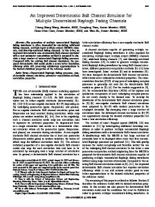
Fig. 2.
Fig. 1. A Layer-2 Optical Transport Network (OTN), bypassing many layer-3 IP routers, and supporting IP-over-DWDM
GR connections through the IP network can be performed by an SDN control-plane when the connections are established, and can use an optimal ’Multicommodity Maximum Flow Minimum Cost’ routing algorithm, without relying on suboptimal best-effort layer 3 IP routing algorithms. The GR technology can also be applied to a Layer 2 transport network, of electrical or optical packet-switches, where ’IP tunnels’ are created using GR connections in the Layer 2 transport network, as also shown in Fig. 1. The IP tunnels could encapsulate IPv4 or IPv6 packets and deliver them from end-to-end transparently and in a protocolindependent manner, bypassing many Layer 3 IP routers, providing deterministic GR service with minimal buffering and queueing delays. By bypassing the Layer 3 IP routers, the energy-use and end-to-end delays can be reduced by 1-2 orders of magnitude, even when using electrical layer 2 switches. The Layer 2 transport network can also use pure Optical Packet Switching, or Hybrid Optoelectronic Packet Switching, which combines optical transmission with electronic processing in a single integrated circuit, using for example the relatively new Silicon-Photonics technology [7]. The transport network can also use MEMS-based optical packet switches (MicroElectro-Mechanical Systems), or wavelength-routed optical packet switches using tunable wavelength converters and an Arrayed Waveguide Grating (AWG) based switch. In this paper, a ’proof-of-concept’ FPGA testbed for the switch-controller and the deterministic GR technology is developed, as shown in Fig. 2. A switch-controller and a minimum-complexity switch for the forwarding plane are synthesized on an Altera DE2-115 board using an Altera Cyclone IV FPGA. Several sets of traffic demands are generated, and for each traffic demand, several deterministic schedules are precomputed. The schedules are downloaded into the FPGA controller of each switch in the forwarding plane. Each controller has several Lookup Tables (LUTs), which control the switch configurations for each time-slot in a scheduling frame. The FPGA testbed is clocked at 52 MHz allowing millions of packet transfers per second, and statistics are recorded. The testbed indicates that multiple FPGA controllers can easily be integrated into a single FPGA. An inexpensive FPGA switch-
1178
The FPGA Testbed: A Linear Array of Routers / Packet Switches
controller on an Altera Cyclone FPGA can easily control an IP router or packet-switch of sizes up to 1024x1024, operating at rates of ≈ 50M packets per second per IO port. Assuming that maximum-size IP packets of about 1500 bytes are used, such a switch would have 1024 IO ports operating at a line-rate of 120 Gbps, with an aggregate capacity exceeding 500 Tbps. Hence, an inexpensive FPGA switch-controller can easily scale to handle IP routers and electrical or optical switches with extremely large capacities. This paper is organized as follows: Section II discusses prior work. Section III discusses the Guaranteed-Rate router. Section IV discusses the FPGA testbed Section V discusses the experimental results. Section VI discusses the use of the proposed controller in a GR layer 2 underlay network. Section VII concludes the paper. II. P RIOR W ORK A packet-switch network G(V, E) with N nodes can admit N × (N − 1) traffic flows for the N × (N − 1) unique sourcedestination or (s,d) pairs, each with a GR, subject to edge capacity constraints. The concept of the maximum-achievable capacity of a packet-switched network has been well-studied. The phrases Capacity Region, Throughput Region, Stability Region, and Schedulability Region have been used to describe the region where the maximum-achievable capacity of a packet-switched network can be realized. A traffic flow is said to be ’Admissible’ if its addition does not violate any edge capacity constraints. Each vector of N × (N − 1) admissible traffic flow rates for all (s, d) pairs defines a point in N × (N − 1) dimensional space. The set of all admissible points defines a polytope in N × (N − 1)-dimensional space, and the convex hull of the polytope defines the Capacity Region of the network. It has been shown that a Maximum Weight Matching (MWM) scheduling algorithm can achieve 100% throughput and stability within one Input-Queued (IQ) router [9]. However, the MWM algorithm has complexity O(N 3 ), which renders it intractable for realistic networks. The Birkoff von Neumann (BVN) algorithm proposed in [10] can schedule traffic through an IQ router with low jitter and with complexity O(N 4.5 ), which is considered intractable. The problem of scheduling packet transmissions in one IQ router to minimize jitter is shown to be NP-HARD in [11]. A polynomial-time
IFIP/IEEE IM 2015 Workshop: 7th International Workshop on Management of the Future Internet (ManFI)
(a) Fig. 3.
(b)
(c)
(a) Basic IQ switch. (b) VOQ design. (c) FPGA Controller controlling an All-Optical Packet Switch [13].
Greedy Low-Jitter Decomposition (GLJD) scheduling algorithm was also proposed in [11]. However, it requires a worstcase speedup of O(logN), rendering it inefficient. These prior low-jitter scheduling algorithms have speedup requirements or very high computation complexities (typically O(N 4.5 ) complexity), rendering them intractable. Ref. [13] introduces the GR-VCS technology, and presents theorems which establish that all admissible traffic demands in any packet-switched network can be simultaneously achieved with deterministic GR connections, with minimal buffering and queueing latency. The paper uses a fast polynomialtime approximation algorithm to solve the minimum-jitter scheduling problem of [11], which is known to be NP-Hard. The paper also presents the design of a minimum-complexity All Optical Packet Switch, as shown in Fig. 3c. III. T HE G UARANTEED -R ATE PACKET S WITCH This section summarizes the GR packet switch [13], which will be implemented in an FPGA. Fig. 3a illustrates a basic GR ’Input-Queued’ (IQ) switch. A router of size M × M consists of M input and output ports IP(i) and OP(i), for 1 ≤ i ≤ M . Each input port has M ’Virtual Output Queues’ (VOQs), where VOQ(i,j) stores packets arriving at IP(i) which are destined for OP(j). Each input port contains an Input-Filter to filter, police and classify incoming packets. Each InputFilter sorts the packets arriving at an input port according to the desired output ports, and forwards the packets to the appropriate VOQ. The switch in Fig. 3a has several schedulers. The Switch-Scheduler controls the switch configuration in each time-slot. The VOQ-Scheduler selects a VOQ for service in each time-slot, and can be controlled from the Switch-Scheduler. Given a static set of traffic demands, these schedulers can be pre-computed and stored in Lookup Tables. Each VOQ can be further split into several smaller virtual queues, as shown in Fig. 3b. A VOQ can contain several ’Flow-VOQs’, where each Flow-VOQ contains the packets associated with one particular end-to-end traffic flow. A VOQ can also contain an ’Aggregate Class-VOQ’ which contains the packets associated with one traffic class. Several traffic classes can be supported. The GR switch can provide GR
service to each flow individually, by creating a flow-schedule which specifies when the Flow-VOQs receive GR service. The GR switch can also provide GR service to each traffic class individually, by creating a schedule which specifies when the Aggregate Class-VOQs receive GR service. The GR switch allocates bandwidth in terms of time-slot reservations, in a scheduling frame with a length of F timeslots. To allocate bandwidth with a resolution of 1% of the line-rate, a scheduling frame length F = 128 can be used. To allocate bandwidth with a resolution of 0.1% of the linerate, a scheduling frame length F = 1024 can be used. The GR switch can use 2 periodic schedules, called the Queue Schedule and Flow Schedule, which are described next. These schedules can easily be computed in microseconds, using the scheduling algorithms presented in [13]. The routers need not be synchronized, as the schedules can be circularly rotated and still remain valid. Definition: A Queue-schedule for one router is a sequence of F partial or full permutation matrices (or bipartite graph matchings) which define the crossbar switch configurations for F time-slots within a scheduling frame. Equivalently, the Queue-schedule defines the active VOQs for each time-slot in the scheduling frame, i.e., V OQ ≡ {V OQt }, 1 ≤ t ≤ F , where V OQt (j, k) = 1 if VOQ(j, k) has a scheduled service opportunity in time-slot t. Each permutation matrix V OQt () identifies several conflict-free VOQs for service in time-slot t. Definition: A Flow-schedule for one router is a sequence of F matrices Zt which identify the Flow-VOQ or Aggregate Class-VOQ to be serviced in each VOQ for the F timeslots within a scheduling frame, given a Queue-schedule which identifies the VOQs to be serviced in each time-slot. Equivalently, Z ≡ {Zt }, 1 ≤ t ≤ F , where Zt (j, k) = f if GR flow f within VOQ(j, k) has a scheduled service opportunity in time-slot t. A. An Integrated Silicon-Photonics Optical Packet Switch A single-chip Silicon-Photonics optical packet switch is shown in Fig. 3c. Packets arrive on incoming fibers, on multiple wavelengths in a DWDM system (Dense Wavelength Division Multiplexing). The use of deterministic GR connections
IFIP/IEEE IM 2015 Workshop: 7th International Workshop on Management of the Future Internet (ManFI)
1179
(a) Fig. 4.
(b)
(a) Evolution of 4 IQs in switch 1. (b) Evolution of a VOQ in switch 1. (c) Evolution of another VOQ in switch 1.
(a) Fig. 5.
(b)
(c)
(a) Distribution of IQ sizes in switch 1. (b) Distribution of IQ sizes in switch 8. (c) Evolution of a VOQ in switch 8.
greatly simplifies the operation of the all-optical switch, as a result of the deterministic TDM periodic schedules: (i) packets arrive to each switch at deterministic times in a periodic schedule on each fiber, (ii) each packet will experience a deterministic queueing delay, and (iii) packets depart each switch at deterministic times in a periodic schedule on each fiber. The SDN control plane configures the FPGA controllers in the forwarding plane to establish deterministic GR connections, thereby removing the need to perform all-optical flow-control or contention-resolution. The FPGA controllers control the optical packet switches in each time-slot of a scheduling frame; The optical demultiplexers are activated to forward packets into optical buffers at the correct timeslots. The optical multiplexers are activated to forward packets from packet buffers, through the optical switch to wavelength converters and onto the an outgoing fiber, in the correct timeslots. The optical switch is activated to perform the periodic queue and flow schedules described earlier. An integrated single-chip Optical Packet Switch can easily be fabricated using the Silicon-Photonics technology [7]. This technology allows for the integration of CMOS logic along with optical waveguides, optical wavelength converters, and optical binary switches, all in the same integrated circuit. The optical packet buffers in Fig. 3c can use a small number of fiber delay loops, which are external to the SiliconPhotonics IC. By using deterministic GR connections, the amount of buffering is reduced by a factor or 1000 or more, thus enabling the fabrication of single-chip integrated optical packet switches. The packet buffers in Fig. 1c can also be implemented in CMOS, as the Silicon-Photonics technology
1180
(c)
integrates all-optical components and CMOS logic together. IBM has already demonstrated single-chip SiliconPhotonics transceivers with ≈ 1 Tbps of aggregate bandwidth [18]. By adding the simple FPGA controllers described in this paper, these existing Silicon-Photonics transceivers can be transformed into programmable Optoelectronic Packet Switches, which can be used in a layer-2 underlay network as shown in Fig. 1. IV. T HE T ESTBED : A L INEAR A RRAY OF 8 ROUTERS /S WITCHES Fig. 2 illustrates the testbed, a linear array of 8 4x4 routers/packet switches supporting 128 traffic flows, which was synthesized and tested in an FPGA. The scheduling framelength F is 1024 time-slots. An SDN control plane routed 128 traffic flows from end-to-end. The average link load is 99.2%, an extremely heavy loading. The network is operating at essentially 100% loads, where every switch and every link are essentially saturated. Each input port at switch 1 receives 32 traffic flows on average from a Packet-Generator module. Each traffic flow has a guaranteed-rate, with between 1 and 200 time-slots reservations per scheduling frame. Each output port at switch 8 sends 32 traffic flows on average to a PacketReceiver module. The deterministic schedules were pre-computed for each router, and downloaded into the switch controllers in the FPGA testbed. The FPGA testbed is then clocked at rates of 52 MHz. Each packet requires about 13 clock periods to move from router to router, so the effective packet rate is about 5 million packets per second per IO port, using the (slow) Altera Cyclone IV FPGA. The results are presented in the next section.
IFIP/IEEE IM 2015 Workshop: 7th International Workshop on Management of the Future Internet (ManFI)
(a) Fig. 6.
(b)
(c)
(a) Ages of all flows, in real-time. (b) Ages of all flows, in normalized-time. (c) Age Deviation from mean for all flows, in normalized-time.
(a)
(b)
(c)
Fig. 7. (a) IDT distribution for each flow, in real-time. (b) IDT distribution for each flow, in normalized-time. (c) IDT distribution for all flows, in normalized-time.
V. E XPERIMENTAL R ESULTS Fig. 4a illustrates the size of the IQs in the first switch versus the time-slot, for 4 scheduling frames. Initially the IQs are empty. The IQs reach a periodic steady-state after the first scheduling frame. Each IQ supports on average 32 traffic flows, and each IQ has an average size of ≤ 16 packets. On average, each traffic flow buffers ≤ 1/2 packet per router, as observed in [13]. The network is operating at 99.2% load. In each time-slot, a packet arrives to and departs from an IQ with probability 0.992. Hence, the IQ size remains constant with probability 0.984. These results confirm that every traffic flow receives deterministic GR service, while exhibiting negligible queueing delays, even at ≈ 100% loads. Fig. 4b and 4c illustrate the size of 2 VOQs out of 4 in the first switch versus the time-slot, for 4 scheduling frames. Initially the VOQs are empty. The VOQs reach a periodic steady-state after the first scheduling frame, where the vector of VOQ states at time-slots 1 ≤ t ≤ F in one scheduling frame remains unchanged in the next scheduling frames. Each VOQ supports on average 8 traffic flows, and each VOQ has an average size of ≤ 4 packets. Fig. 5a illustrates the distribution of the 4 IQ sizes in the first switch, over 10 scheduling frames. There are 4 dominant spikes corresponding to the 4 periodic steady-state values. The start-up effects of the first scheduling frame, when the IQs are filling up towards their periodic steady-state values, are responsible for the remaining smaller spikes. The average IQ size in the first switch is ≤ 16 packets. Fig. 5b illustrates the distribution of the 4 IQ sizes in the last switch (#8), over 10 scheduling frames. The average IQ
size in the last switch is also ≤ 16 packets. These graphs are consistent with theorems in [13], which state that the buffering remains negligible along an end-to-end path. Fig. 5c illustrate the size of one VOQ out of 4 in the last switch versus the time-slot, for the first 4 scheduling frames. Initially the VOQs are empty. The VOQs will reach a periodic steady-state after 6 scheduling frames. The VOQ does not quite reach the steady-state in the first 4 scheduling frames shown in Fig. 5c. Once again, each VOQ supports on average 8 traffic flows, and this particular VOQ will have an average size of ≤ 4 packets. Fig. 6a illustrates the end-to-end packet ages as the packets leave the last stage, expressed in time-slots. The packets belonging to the same flow have the same color, and 8 colors are used to color the 128 flows. The packet ages range from 80...200 time-slots. Assuming 1500 byte packets and 100 Gbps links, each time-slot takes 0.12 microsec, and the end-to-end packet ages range from 9.6...24 microsec, reflecting very small end-to-end queueing delays. Fig. 6b illustrates the packet ages as the packets leave the last stage, expressed in normalized time. Each unit of normalized time is defined as the ideal average time between packets in a perfectly-scheduled smooth flow with a constant guaranteed-rate, which can be denoted τ ∗ . (This unit is called the ’Ideal Inter-departure Time’ or IIDT in [13].) If every packet waits one unit of normalized time per switch, then the average age would be 8 τ ∗ . The packet ages range from between about 0...8 τ ∗ , indicating that each packet experiences very little queueing in every router. On average, each packet experiences about 1/2 τ ∗ of queueing in every router.
IFIP/IEEE IM 2015 Workshop: 7th International Workshop on Management of the Future Internet (ManFI)
1181
Fig. 6c illustrates the deviation of packet age from the mean packet age, for each flow. The packets belonging to the same flow have the same color, and 8 colors are used to color the 128 flows. This graph illustrates that each flow receives essentiallyperfect GR service, where the deviation in packet age from the mean age is very little, typically less than 1 or 2 τ ∗ . Fg. 7a illustrates the packet ’Inter-Departure-Time’ (IDT) as the packets leave the last stage, expressed in time-slots. The packets belonging to the same flow have the same color, and 8 colors are used to color the 128 flows. The packet IDTs range from between about 0 ... 200 time-slots. Fig. 7b illustrates the packet IDTs as the packets leave the last stage, for each individual flow, expressed in normalized time. The deviation of the packet IDTs from mean ideal IDT range from between about 0...2 τ ∗ , indicating that each packet experiences very little queueing in every router. On average, every packet is received at the output of the last stage at a near-perfect smooth guaranteed rate, with very little deviation in the time between packets. Fig. 7c illustrates the packet IDTs as the packets leave the last stage, for all flows combined into one probability distribution, expressed in normalized time. The deviation of the overall packet IDT from mean ideal IDT range from -1...+1 τ ∗ , indicating that each packet experiences very little queueing in every router. On average, every packet is received at the output of the last stage at a near perfect smooth guaranteed rate, with very little deviation in the time between packets. VI. A N O PTICAL U NDERLAY FOR IP OVER DWDM Fig. 8 illustrates an OPS underlay network supporting IP over DWDM over a USA-Canada backbone network, with 39 nodes (cities) and 122 edges. The bold lines represent physical links between IP routers in the cities. The dotted lines represent congestion-free Virtual Links (VLs) between cities. An SDN control plane can program the VLs into the optical underlay as desired. At each city, an inexpensive FPGA controller controls the switch/router to establish deterministic GR connections, and can achieve link loads of 100%. In Fig. 8, nearly 400 VLs are embedded into the underlay. Five cities selected at random (Los Angeles, Chicago, New York, Miami, Vancouver) each have 38 VLs going to the 38 other cities, and 38 VLs received from the 38 other cities. Each of these 5 cities can reach any other city over a ’onehop’ Virtual Link, and the converse is also true. Each VL provides deterministic ’one-hop’ GR transport connections (i.e., IP tunnels) between 2 cities, where the end-to-end delays are equal to the fiber delay over the physical links. The IP tunnels bypass layer 3 processing at the IP routers, thereby reducing latency and energy use. The end-to-end delays over the Virtual Links are effectively reduced to the fiber time of flight, i.e., the speed of light in fiber. For example, the fiber latency between New York and Los Angeles is ≈ 2030 millisec (depending upon the physical path), while the end-to-end queueing delay over the Virtual Link is ≈ 10-20 microseconds. The end-to-end queueing delays are ≈ 1000 times smaller than the fiber delays, assuming 100 Gbps links
1182
Fig. 8. A USA-Canada backbone network, supporting low-latency VirtualLinks (IP-tunnels) originating at 5 cities.
and 1500 byte packets. The remaining 33 cities can reach any other city by traversing 2 VLs. Of course, they can also use the existing layer-3 best-effort IP routing, which will use 10-100 times more energy and incur 1000 times more queuing delay. Each IP router is unaware of the underlay network. From the layer 3 perspective, an IP router sees perfect ’one-hop’ lowlatency GR ’Virtual Links’ to its neighbouring routers, which it can exploit in its OSPF and BGP routing algorithms. The OSPF and BGP routing algorithms often minimize the number of hops, and they will naturally exploit the IP tunnels, which are viewed as one-hop connections. In Fig. 8, it is straight-forward to embed a full mesh of connections, where every city has a 1 hop VL to every other city. Such a full mesh of connections between 39 cities would require 39 × 38 = 1,482 Virtual Links to be embedded into the underlay. An SDN control plane can use a Multicommodity Maximum-Flow Minimum-Energy routing algorithm to route these VLs in an optimal manner [12]. VII. C ONCLUSION This paper has described an FPGA controller which supports low-latency deterministic ’Guaranteed-Rate’ (GR) transport connections for cloud services. An SDN control-plane can manage the FPGA controllers to create deterministic GR connections in a forwarding-plane of IP routers, or electrical / optical packet switches. The testbed results confirm that deterministic GR transport connections can be configured on a programmable underlay network, where links operate at effectively 100% utilization, and where the expected end-toend delays are effectively reduced to the fiber latency. Using inexpensive FPGA controllers, an SDN control-plane can add deterministic GR services to IP routers in layer 3 (yielding a Deterministic Internet), to MPLS, Ethernet, InfiniBand and Fibre Channel switches in layer 2, and to an underlay network using All-Optical Packet Switching or hybrid Optoelectronic Packet Switching. The ability to bypass layer-3 IP routers using a layer-2 underlay can also improve the energy efficiency significantly. An inexpensive FPGA controller can handle routers or switches with aggregate data-rates in the hundreds of Tbps. (A demonstration of the technology will be shown at IFIP/IEEE IM demonstration session [15].)
IFIP/IEEE IM 2015 Workshop: 7th International Workshop on Management of the Future Internet (ManFI)
R EFERENCES [1] M. Ford, ”Workshop Report: Reducing Internet Latency 2013”, ACM SIGCOMM CCR, Vol. 44, No. 2, April 2014 [2] Internet Society, ”Workshop on Reducing Latency”, URL: http://www.internetsociety.org/latency2013 [3] A. Singla, B. Chandrasekaran, P.B. Godfrey, B. Maggs, ”The Internet at The Speed of Light”, ACM Hotnets 2014, Oct. 2014, LA, USA [4] Ciena Networks, ”Ultra-Low-Latency Networking: Milliseconds can mean Millions”, www.ciena.com, 2013 [5] A. Afanasyev, N. Tilly, P. Reiher and L. Kleinrock, ”Host-to-Host Congestion Control for TCP”, IEEE Comm. Surveys and Tutorials, 3Q, 2010. [6] H. Kim and N. Feamster, ”Improving Network Management with Software Defined Networking”, IEEE Comm. Mag., Vol. 5, no. 2, 2013 [7] Y.A. Vlasov, ”Silicon-CMOS Integrated Nano-Photonics for Computer and Data-Communications Beyond 100G”, IEEE Comm. Mag., Feb. 2012 [8] IETF RFC 2212, S. Shenker, C. Partridge, R. Guerin, ”Specification of Guaranteed Quality of Service”, Sept. 1997 [9] V. Anantharam, N. McKeown, A. Mekittikul and J. Walrand, ”Achieving 100% Throughput in an Input Queued Switch”, Trans. Comm., vol. 47, no. 8, 1999. [10] W.J. Chen, C-S. Chang, and H-Y. Huang, ”Birkhoff-von Neumann Input Buffered Crossbar Switches for Guaranteed-Rate Services, IEEE Trans. Comm., Vol. 49, No. 7, July 2001.
[11] I. Keslassy, M. Kodialam, T.V. Lakshman and D. Stilliadis, ”On Guaranteed Smooth Scheduling for Input-Queued Switches”, IEEE/ACM Trans. Networking, Vol. 13, No. 6, Dec. 2005 [12] T.H. Szymanski, ”Max-Flow Min-Cost Routing in a Future Internet with Improved QoS Guarantees”, IEEE Trans. Comm., Vol. 61, No. 4, April 2013. [13] T.H. Szymanski, ”An Ultra Low Latency Guaranteed-Rate Internet for Cloud Services”, IEEE Trans. on Networking, at IEEExplore, Oct. 2014 [14] S. Iyer, RR. Kompella, N. Mckeown, ”Designing Packet Buffers for Router Linecards”, IEEE Trans. Networking, Vol. 16, No. 3, June 2008 [15] M. Rezaee and T.H. Szymanski, ”Demonstration of an FPGA Controller for Guaranteed-Rate Optical Packet Switching”, IFIP/IEEE IM, Ottawa, Canada, May 2015. [16] S.J. Ben Yoo, ”Energy Efficiency in the Future Internet: The Role of Optical Packet Switching and Optical Label Switching”, IEEE JSTQE, Vol. 17, No. 2, March/April 2011 [17] R.S. Tucker, R. Parthiban, J. Baliga, K. Hinton, R.W.A. Ayre, and W.V. Sorin, ”Evolution of WDM Optical IP Networks: A Cost and Energy Perspective”, OSA JLT, Vol. 27, No. 3, 2009 [18] F.E. Doany, G.L. Benjamin, M.K. Daniel, A.V. Rylyakov, C. Baks, C.Jahnes, F. Libsch, and C.L. Schow, ”Terabit/Sec VCSEL-Based 48Channel Optical Module Based on Holey CMOS Transceiver IC.”, IEEE JLT, Vol. 31, No. 4, 2013 [19] Greentouch White Paper, ”Greentouch Green Meter Research Study: Reducing Net Energy Consumption in Communications Networks by up to 90% by 2020”, June 2013, www.greentouch.org
IFIP/IEEE IM 2015 Workshop: 7th International Workshop on Management of the Future Internet (ManFI)
1183