LU TP 04-27
An improved algorithm for simulations of divergent-light halos Lars Gislén, Jan O. Mattsson, and Bo Söderberg*. Divergent-light halos are produced when light from nearby light sources is scattered by ice crystals in the atmosphere. We present a theory of divergent-light halos leading to an improved algorithm for the simulation of such halos. Contrary to the algorithm we presented earlier for simulating such halos, the new algorithm includes a mathematically rigorous weighting of the events. The computer implementation is very compact and the whole procedure is elegant and conceptually easy to understand. We also present a new simulation atlas showing halos produced by crystals of different shapes and orientations for a set of elevations of the light source. OCIS codes:
010.1290, 010. 2940, 010.3920
1. Introduction In two earlier papers1,2 we presented a new and efficient method for simulating divergent-light halos as well as comparisons with observations of such halos in the field. In these papers we also described the differences and similarities between ordinary parallel-light halos and divergent-light halos and explained why it is much more difficult to simulate a divergent-light halo than a parallel-light halo, a fact that explains why almost no such simulations have been published. For details we refer to our previous papers. Although the algorithm presented in these papers is computationally quite efficient it has draw-backs. The mathematics is somewhat involved and the computer program that implements the algorithm is lengthy and not very transparent. A more serious matter, as pointed out by Jarmo Moilanen3, is that the algorithm lacks a proper event-weighting which, for instance gives a wrong intensity distribution in the divergent-light halo produced by randomly oriented ice crystals. The present paper presents an improved algorithm that has a mathematically rigorous weighting of the events. Like the previous algorithm it is based on spatial rotations but instead of using a restricted set of rotations we now allow the full set of rotations in space. The algorithm is also much simpler, the computer implementation is very compact and the whole procedure is elegant and conceptually easy to understand.
2. Theory 2.1 Assumptions Let the light source be located at the origin O = (0, 0, 0) , and the observer at a fixed position R at a distance R from the origin. Let the cloud of ice crystals be characterized by a homogeneous number density n and a fixed distribution Q(U) over possible crystal orientations, as given by applying a SO(3) rotation U to some standard orientation. Let the point-like light source have a total power P, isotropically radiated, and let A be the small aperture of the observer's eye. Assume the scattering dσ by a single crystal to be described by a differential cross section 2 , given an d bˆ incident ray direction aˆ , a scattered ray direction bˆ , and a crystal orientation U, *
L. Gislén (
[email protected]) and B. Söderberg (
[email protected]) are with the Department of Theoretical Physics. J. O. Mattsson (
[email protected])is with the Department of Physical Geography and Ecosystems Analysis, Lund University, Sweden.
where aˆ and bˆ are unit vectors. We express this cross section as a typical single crystal cross section σ0 times a distribution over the scattered direction p bˆ | aˆ , U ,
(
normalized such that ∫ d 2bˆ p bˆ | aˆ ,U = σ (aˆ ,U) /σ 0 ~ 1.
(
)
)
(1)
We assume that the wavelength of the light is such that the scattering is accurately described by a ray-tracing model. We further assume that the scattering is rotationally covariant, i.e. it depends only on the relative orientations of the incoming and scattered radiation and the orientation of the crystal. This means that the distribution p is invariant under rotations, p bˆ | aˆ , U = p U −1bˆ | U −1aˆ , U −1U = p U −1bˆ | U −1aˆ , 1 (2)
(
) (
) (
)
where 1 denotes the crystal in the standard orientation. 2.2 Halo distribution If a crystal of orientation U is present at a position a = aaˆ , a = a , it experiences a light intensity (power/area) given by I = P /( 4 πa 2 ) . The total power scattered by the crystal is P = Iσ (aˆ , U), which is then distributed over different directions bˆ as
(
s
)
σ 0 Ip bˆ | aˆ , U . The observer is located at R, i.e. at position b = R − a relative to the crystal, and sees only scattered rays coming in the direction bˆ . Hence the intensity of the scattered radiation seen by the observer is I = σ Ip bˆ | aˆ , U / b 2 , which implies a s
0
(
)
total observed, scattered power per solid angle from the direction − bˆ given by P1 = AI s or Aσ 0 P P1 = p bˆ | aˆ , U 2 2 4 πa b
(
)
(3)
Now, assume that the number density of crystals, n, be low enough such that (i) the intensity I as described above does not noticeably diminish due to the scattering. (ii) we can neglect multiple scattering. Then we can simply sum the scattered power from all crystals, which means integrating over positions a with a factor n, and over orientations U with weight Q(U) . This yields, for the total power of scattered radiation that reaches the observer's eye, the expression Aσ 0 Pn d 3a (4) PO = DU Q(U)p bˆ | aˆ , U 4π ∫ a 2 b 2 ∫ The integration differential DU represents the three parameters that describe the rotation U.
(
)
It appears natural to normalize this expression to the power Piso , obtained by assuming that the scattering is completely isotropic and that the crystal orientations are random. σ (aˆ , U) ≈ 1 / 4 π , yielding This corresponds to p bˆ | aˆ , U = σ0
(
)
Aσ 0 Pn d 3a Aσ 0 Pn d 3a Aσ 0 Pnπ (5) D Q = = U U ( ) 2 2 2∫ 2 2 2 ∫ ∫ ab ab 4π 4π 4R Dividing the observed, scattered power PO by Piso gives a suitable expression for the observed scattered radiation 4 R d 3a (6) Z = 2 ∫ 2 2 ∫ DU Q(U)p bˆ | aˆ , U π ab Piso =
(
)
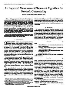
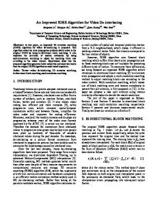
2.3 Bipolar angles and Minnaert's cigars In the halo formalism it is convenient to introduce bipolar angles for parametrizing crystal positions in space. These bipolar angles are defined with respect to two points which we choose as O and R. Assume temporarily R to be along the positive z axis, i. e. R = (0, 0, R) . An arbitrary point in space (a crystal position), a = ( x, y, z ) , can be expressed in bipolar angles ω, θ, and φ with respect to O and R, where θ and φ are usual polar angles with respect to O, while ω is defined by rewriting the radial coordinate a as R sin(ω − θ ) (7) a= sin ω and we obtain Rsin(ω − θ ) (8) a= (sin θ cos φ,sin θ sin φ,cosθ ) sin ω with the ranges 0 ≤θ ≤ω ≤π (9) 0 ≤ φ ≤ 2π Note that the complementary vector b from a to R becomes Rsin θ (10) b=R−a= (− sin(ω − θ ) cos φ, − sin(ω − θ ) sin φ,cos(ω − θ )) sin ω The angle ψ = ω − θ replaces the polar angle θ for b, and ω = ψ + θ is the sum of the two polar angles, which is also the angle between a and b. A fixed value of ω defines a particular surface, a Minnaert's cigar4 (fig. 1), which is parametrized by the polar angles θ and φ.For the geometry of such cigars see fig. 2 a, b.
Figure 1a, b, c. Minnaert's cigars for scattering angles of 22˚, 45˚, and 150˚, respectively.
ω a
θ
b
ϕ
ψ
R/2
R/2
a
b ψ
θ R
ω
Figure 2a. Cigar geometry.
b. Locating a point on the cigar.
In particular note that the polar angles (ψ,ϕ ) specify the apparent location of a crystal relative to the light source as seen by the observer (fig. 2 b). The volume element becomes sin 2 θ sin 2 (ω − θ ) (11) d 3a = R 3 dω dθ dφ sin 4 ω Since a = R sin(ω − φ ) / sin ω and b = R sin θ / sin ω , this yields a very simple expression for the measure that appears in the halo distribution d 3a 1 (12) = dω dθ dφ a 2b 2 R 2.4 Standard event distribution When simulating a halo on a computer, the symmetry of the scattering distribution as expressed in (2) is very convenient. We wish to exploit this symmetry by reusing standard events by applying SO(3) rotations to them. A standard event is defined by having the crystal in a standard orientation (U = 1), an incident ray with random direction aˆ 0 , and a direction bˆ 0 in which light is scattered. The direction of scattering is found by ray-tracing the incident ray through the crystal until it exits. The scattering angle, ω = arccos(a 0 ⋅ b0 ) is invariant under any rotation. Only a two-dimensional manifold of rotated versions of a standard event is consistent with observability and constitute observable events – for a rotated standard event with a particular scattering angle ω to be observable, the crystal must be located on a particular Minnaert's cigar surface between the light source and the observer. We need an expression for the distribution of a single, simulated standard event. A random incident direction corresponds to the measure d 2aˆ 0 / 4 π . The incident ray is made to randomly hit a disk perpendicular to aˆ 0 , with an area σ 0 large enough to contain the projection the crystal. A crystal in its standard orientation U = 1 yields for the direction of scatter, bˆ 0 , the distribution p bˆ 0 | aˆ 0 , 1 . Thus for all possible versions
(
)
of events we get the integral d 2aˆ 0 (13) ∫ 4π ∫ d 2bˆ 0 p bˆ 0 | aˆ 0,1 ≤ 1 The inequality appears because some incident rays will hit the disk outside the projection of the crystal. These events will be discarded.
(
)
In a computer simulation of a halo, a large number of standard events are produced, and the natural question is how to use them to compute Z, or rather dZ / d 2 bˆ , the halo intensity distribution. 2.5 Rewriting Z in terms of standard events The previously computed expression for the properly normalized, observed scattering power can, using a Dirac delta function, be written 4 R d 3 a d 3b (14) Z = 2 ∫ 2 ∫ 2 δ (a + b − R)∫ DU Q(U)p bˆ | aˆ , U a b π We want to rewrite this expression in terms of contributions from standard events aˆ 0 , bˆ 0 . This obviously requires rotations of the arguments of p in the integrand to the standard orientation. This means introducing rotated versions aˆ 0 and bˆ 0 of the real ray directions such that aˆ = Uaˆ and bˆ = Ubˆ . To that end, we note that the
(
(
)
)
0
0
integration over the the parameters of the SO(3) rotation U can be written as the integration over the pre-images, aˆ 0 , bˆ 0 , of the directions aˆ , bˆ , with a Dirac delta function securing the correct pair-wise scalar product, i. e. DU = d 2aˆ 0 d 2bˆ 0δ aˆ 0 ⋅ bˆ 0 − aˆ ⋅ bˆ (15)
(
)
This yields, using the symmetry (2) of p, 4 R d 3 a d 3b Z = 2 ∫ 2 ∫ 2 δ (a + b − R)∫ d 2 aˆ 0 d 2 bˆ 0δ aˆ 0 ⋅ bˆ 0 − aˆ ⋅ bˆ Q(U)p bˆ 0 | aˆ 0 , 1 a b π (16) After some reordering this can be written in the convenient form d 2aˆ 0 (17) Z= ∫ d 2bˆ 0 p bˆ 0 | aˆ 0 , 1 W aˆ 0 , bˆ 0 ∫ 4π i.e. as an integration over standard events aˆ 0 , bˆ 0 with one weight factor p that
(
(
) (
(
)
)
(
)
)
handles the outcome of the ray-tracing and a second weight factor W, representing their total contribution to Z, which is 16 d 3a d 3b W aˆ 0 , bˆ 0 = ∫ a2 ∫ b2 δ(a + b − R)δ aˆ 0 ⋅ bˆ 0 − aˆ ⋅ bˆ Q(U) R (18) Here, U is seen as depending on aˆ , bˆ , aˆ 0 , and bˆ 0 . Explicitly we have ˆ ˆ T − cosω ab ˆ ˆ T + aˆ × bˆ aˆ × bˆ T ˆ ˆ T0 + bb ˆ ˆ T0 + ba aa 0 0 0 0 (19) U= 2 sin ω where the vectors are considered to be column matrices and the superscript "T" denotes matrix transpose.
(
)
(
(
) (
)
)(
)
The expression for W suggests that bipolar angles would be convenient, yielding ω 2π 16 π W = d d dφ δ cosω − aˆ 0 ⋅ bˆ 0 Q(U) ω θ (20) ∫ ∫ ∫ π 0 0 0 The Dirac delta function fixes the value of ω and thus a definite cigar, as is to be expected; a rotation of the directions aˆ 0 and bˆ 0 cannot change their relative angle. Eliminating the ω integral gives a very simple expression for the event weight: 32ω ω dθ 2 π dφ W = (21) ∫ ∫ Q(U) sin ω 0 ω 0 2π
(
)
where now U is to be regarded as a function of ω, θ, and φ. The weight is evenly distributed over cigar angles θ and φ, apart from the factor Q(U) , which modifies the weight distribution depending on the crystal orientation associated with a particular point on the cigar. The weight distribution is seen to decompose into two parts, the intrinsic cigar weight ω that is proportional to , and the factor Q(U) which modifies the uniform cigar sin ω dθ dϕ by suppressing points on the cigar that correspond to less probable measure ω 2π crystal orientations. We see that effectively we have split the halo intensity distribution into three factors: one describing a single crystal scattering in a standard crystal frame, another that gives the associated intensity contribution to the weight for isotropic crystal orientations, and finally one that takes into account the actual distribution of crystal orientations. This factorization is not unique but turns out to be convenient for the implementation of our computer algorithm.
3. Implementation The algorithm we use can be summarized as follows: 1) Assume a standard orientation the crystal such that the main axis of the crystal is in the z direction (vertical), and one of the crystal side faces is parallel to the xz plane. This defines the standard frame U = 1. Generate a random incident ray, ray-trace it through the crystal to get a scattered ray. The directions of the incident and scattered rays aˆ 0 , bˆ 0 , then completely specify the event, given the standard orientation of the
(
)
crystal.
(
)
2) The scattering angle ω = arccos aˆ 0 ⋅ bˆ 0 defines a specific Minnaert's cigar with its axis pointing away from the light source at O towards the observer at R. The contribution weight of an event with a scattering angle ω is proportional to ω / sin ω . We implement this weight by reusing each standard event a number of times that is proportional to this weight, where we have normally chosen the proportionality factor K = 20. The choice of the factor K requires some experimentation. If Q(U) is narrow, this factor may be set fairly large in order to reduce computation time. In the opposite case, as in the case of a random orientation of the crystals, a too large factor will "overexpose" the halo display. 3) For each usage of a standard event, select a point on the cigar by randomly choosing polar angles θ in the interval [0,ω] and ϕ in [0,2π]. This implements the dθ dϕ measure . Note that the random choice of θ is equivalent of choosing the ω 2π observer's polar angle ψ randomly in [0,ω]. Given the vector R from the light source to the observer, the polar angles uniquely determine the rotation U that gives the orientation of the crystal for the observable event.
4) We finally determine the value of Q(U) associated with the actual rotated crystal orientation and plot a point in the sky in the reverse direction −bˆ (ψ, φ ) of the scattered ray with a probability proportional to this value. The weight ω / sin ω diverges for back-scattering, ω = π . Such events, as seen by the observer, are either concentrated in the direction of the light source or in the opposite direction or correspond to rays scattered by crystals very far away. The divergence is a consequence of our approximation being valid only for crystal distances that are small compared to the mean free path. We handle this divergence by setting the weight for scattering angles larger than 179˚ equal to the weight at 179˚.
4. A limiting case The model here also allows us to describe and simulate what happens when the distance between the light source and the observer is very large. This will reduce the influence of parts of the Minnaert's cigar that are far from the observer. There could be several reasons for this: 1) The cloud of ice crystals is finite in extension. 2) Rays from distant crystals are absorbed by the air. There is also an intensity threshold for the eye below which it will not register light. 3) Double scattering and defects, particularly in smaller crystals, will spread the rays away from the original, single scattering direction. 4) Possibly diffractive effects could, for very small crystals, also spread the light and diminish the light intensity. A simple way to simulate the distance dependence is to cut away more distant parts of the cigar by generating points on the cigar only within a small sphere of radius r, centered at the position of the observer. A light source at infinite distance then corresponds to letting this radius going to zero. Simple geometrical considerations (see fig. 3) imply that if we assume r