University of Florida, Dept. of Mechanical and Aerospace Engineering, PO Box ...... 21581, ASME Design Engineering Technical Conferences, September 9-13, ... the 21st International Modal Analysis Conference, February 3-6, Kissimmee, FL ... Dynamics Section, Department of Mechanical Engineering, Imperial College, ...
An Improved RCSA Model for Tool Point Frequency Response Prediction G. Scott Duncan Graduate Student
Tony L. Schmitz Assistant Professor
University of Florida, Dept. of Mechanical and Aerospace Engineering, PO Box 116300 Gainesville, Florida 32611 Nomenclature kx cx ω
linear spring linear damper frequency (rad/s)
kθ cθ
rotational spring rotational damper
Gjk(ω) GSjk(ω) Xj Θj Fk Mk
assembly receptance measured at coordinate j for excitation at coordinate k subassembly receptance measured at coordinate j for excitation at coordinate k assembly linear displacement at coordinate j assembly rotational displacement at coordinate j force applied to the assembly at coordinate k moment applied to the assembly at coordinate k
Rjk(ω) xj fk mk
θj
substructure receptance measured at coordinate j for excitation at coordinate k assembly linear displacement at coordinate j assembly rotational displacement at coordinate j force applied to the assembly at coordinate k moment applied to the assembly at coordinate k
Hjk Ljk Njk Pjk
linear displacement to force receptance linear displacement to moment receptance rotational displacement to force receptance rotational displacement to moment receptance
ρ do Eh Ih m
density outside diameter holder modulus of elasticity holder 2nd area moment of inertia mass
ρt di Et It
η
density of tool inside diameter tool modulus of elasticity tool 2nd area moment of inertia structural damping factor
ρh
density of holder
L
length
Abstract In this paper we present the second generation Receptance Coupling Substructure Analysis (RCSA) method, which is used to predict the tool point dynamic response for milling applications. This method divides the spindleholder-tool assembly into three substructures: the spindle-holder base; the extended holder; and the tool. The tool and extended holder receptances are determined analytically, while the spindle-holder base subassembly receptances are determined experimentally using a ‘standard’ test holder and finite difference calculations. To predict the tool point dynamics, RCSA is used to rigidly couple the three substructures. Experimental validation is provided. 1. Introduction A significant obstacle to the successful implementation of milling in production environments is chatter, or unstable machining. Many research efforts geared toward the understanding and avoidance of chatter have been
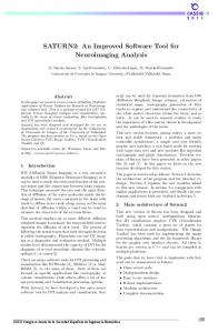
carried out [e.g., 1-24]. This work has led to the development of stability lobe diagrams that identify stable and unstable cutting zones as a function of the chip width and spindle speed. However, the methods used to produce these diagrams, whether analytic or time-domain, require knowledge of the tool point dynamics. The required dynamic model is typically obtained using impact testing, where an instrumented hammer is used to excite the tool at its free end (i.e., the tool point) and the resulting vibration measured using an appropriate transducer, typically a low mass accelerometer. However, due to the large number of spindle, holder, and tool combinations, the required testing time can be significant. Therefore, a model which is able to predict the tool point response based on minimum input data is the preferred alternative. The purpose of this paper is to build on the previous work of Schmitz et al. [25-27], which describes tool point frequency response function, or receptance, prediction using the Receptance Coupling Substructure Analysis (RCSA) method. In these previous studies, a two component model of the machine-spindle-holder-tool assembly was defined. The machine-spindle-holder displacement-to-force receptance was recorded using impact testing, while the tool was modeled analytically. The tool and machine-spindle-holder substructure receptances were then coupled through linear and rotational springs and dampers; kX see the model in Fig. 1, where kx and kθ are the linear and rotational springs, cx and cθ are the linear and rotational ᒕ1 ᒕ2 k ᒕ ᒕ3 viscous dampers, component A represents the tool, and component B the machine-spindle-holder. While the purpose F 1 CX of the springs and dampers between the tool and holder was X1 to capture the effects of a potentially non-rigid, damped X 2 Cᒕ X3 connection, it is likely that these connections served to compensate for the fact that the displacement-to-moment, Figure 1: Previous two component RCSA rotation-to-force, and rotation-to-moment receptances at the model. An external force, F1(t), is applied to free end of the holder were assumed zero (i.e., perfectly the free end of the tool (A) to determine the rigid). Although it was shown in reference [28] that this two assembly X1/F1 receptance. The tool is component model provides a valid approximation for a coupled to the machine-spindle-holder (B) flexible tool clamped in a stiff spindle-holder, it does not offer through springs and dampers. the most generalized solution.
A
B
In order to enable RCSA predictions for a wider variety of machine-spindle-holder-tool combinations, an improved three component model is presented here. In this model, the machine-spindle-holder substructure is separated into two parts: 1) the machine, spindle, holder taper, and portion of the holder nearest the spindle with standard geometry from one holder to another (hereafter referred to as the spindle-holder base subassembly); and 2) the remaining portion of the holder from the base to the free end (hereafter referred to as the extended holder subassembly). A technique for determining the rotation-to-force/moment and displacement-to-moment receptances for the free end of the spindle-holder base subassembly using only displacement-to-force measurements is also described. The experimental procedure involves direct and cross displacement-to-force measurements of a simple geometry ‘standard’ holder clamped in the spindle to be modeled. The portion of the standard holder beyond the section with consistent geometry from holder-to-holder is then removed in simulation using an inverse receptance coupling approach (i.e., decomposition) to identify the four spindle-holder base subassembly receptances. These receptances are then rigidly coupled to models of the actual holder and tool (the kx, kθ, cx, and cθ fitting parameters are no longer required). In this way, the tool point response for any holder and tool combination can be predicted from a single set of measurements completed on the desired machinespindle. In the following sections, the method is described and experimental validation is presented. 2. Background and notation Substructure analysis, or component mode synthesis, methods have been used for several decades to predict the dynamic response of complicated assemblies using measurements and/or models of the individual components, or substructures. These components can be represented by spatial mass, stiffness, and damping data, modal data, or receptances [e.g., 29-43]. The latter representation is preferred in situations where the assembly receptances are the desired analysis output, as is the case in this research.
Assembled
d
c
Ma, Θa a
b
Fa, Xa
Unassembled system Rigid
II d
c
I b
a
Figure 2: Two rigidly connected
For an assembly consisting of two rigidly connected substructures, as shown in Fig. 2, the assembly receptance, Gjk(ω), can be expressed as shown in Eq. 1, where ω is the frequency, Xj and Θj are the assembly displacement and rotation at coordinate j, and Fk and Mk are the force and moment applied to the assembly at coordinate k. If coordinate j is coincident with coordinate k, the receptance is referred to as a direct receptance; otherwise, it is a cross receptance. For the purposes of this paper, the nomenclature Gjk(ω) is used to describe the receptances that are produced when two substructures (or subassemblies) are coupled to produce the final assembly. The nomenclature GSjk(ω) will replace Gjk(ω) in all relevant equations when two substructures (or subassemblies) are coupled that do not form the final assembly. The substructure receptances, Rjk(ω), are defined in Eq. 2, where xj and θj are the substructure displacement and rotation at coordinate j, and fk and mk are the force and moment applied to the substructure at coordinate k [44].
X j F G jk (ω ) = k Θ j F k
Xj M k H jk = Θ j N jk M k
L jk Pjk
xj f R jk (ω ) = k θ j f k
(1)
xj m k h jk = θ j n jk m k
l jk p jk
(2)
Based on the coordinates defined in Fig. 2, the equations to determine the assembly direct receptances, Gaa(ω) and Gdd(ω), and the assembly cross receptances, Gad(ω)and Gda(ω), can be written as a function of the substructure receptances as shown in Eqs. 3-6, where rigid connection has been applied [45].
Xa F G aa (ω ) = a Θ a Fa
Xa Ma = R aa − R ab (Rbb + Rcc )−1 Rba Θa M a
Xa F G ad (ω ) = d Θ a Fd
Xa Md = R ab (Rbb + Rcc )−1 Rcd Θa M d
(3)
(5)
Xd F G dd (ω ) = d Θ d Fd
Xd Md = R dd − R dc (Rbb + Rcc )−1 Rcd (4) Θd M d
Xd F G da (ω ) = a Θ d Fa
Xd Ma = R dc (Rbb + Rcc ) −1 Rba Θd M a
(6)
Bishop and Johnson [46] presented closed-form receptance functions for the analysis of flexural vibrations of uniform Euler-Bernoulli beams with free, fixed, sliding, and pinned boundary conditions. In this work we apply the Bishop and Johnson expressions for free-free beam receptances to model the holder and tool substructures. As a convenience to the reader, the relevant Bishop and Johnson formulas are included in Appendix A. 3. Spindle-holder base subassembly identification The experimental procedure used to determine the receptances at the free end of the spindle-holder base subassembly, GSjk(ω), is described in this section. It is composed of three primary steps. First, the standard holder displacement-to-force direct and cross receptances are determined by impact testing. The standard holder geometry, which was selected to approximate a broad range of potential holders, is provided in Fig. 3. Second, these results are used to determine the three other direct receptances at the free end of the standard holder. Third, the section of the standard holder which is not common to other holders (see Fig. 4) is removed using inverse receptance coupling to determine all four spindle-holder base subassembly receptances. Each step of the procedure is described in the following sections.
3c
3b S
Spindle
Taper
Standard holder
Figure 3: Standard holder
3 S
3.1 Standard test holder receptances
Extended holder subassembly
Spindleholder base subassembly 5
The standard holder was mounted in a rolling element bearing, direct drive high-speed spindle as shown in Fig. 3 3a 3 4 3b (HSK-63A spindle-holder interface). The four subassembly receptances were determined by measuring the direct, H33, and cross, H33b, and H33c, displacement-to-force receptances on the standard holder, applying a 2nd-order backward finite difference method to find L33 (and, equivalently, N33) [47], and then synthesizing P33. For the cross displacement-toforce measurements, the distance S should be selected to II I increase the difference in relative amplitudes between H33, H33b, and H33c without leading to a poor signal-to-noise ratio Figure 4: Standard holder substructures for for the H33c measurement (i.e., many of the lower frequency inverse receptance coupling. spindle-holder modes resemble a fixed-free fundamental mode shape and have very small amplitudes near the spindle face). Practically, we have observed that the finite difference results improve as S is increased; however, for large values, error is introduced into the calculated finite-difference slope. We used a value of 25.4 mm for this study. The receptance L33 is determined from the measured displacement-to-force receptances using Eq. 7. By reciprocity, N33 can be set equal to L33. The remaining receptance, P33, is synthesized from H33, L33, and N33, as shown in Eq. 8 [40].
L33 =
3H 33 − 4 H 33b + H 33c 2S
(7)
P33 =
Θ3 M3
F3 X 3 Θ 3 L33 N 33 L33 = = X 3 M 3 F3 H 33 H 33
2
=
(8)
Due to the subtraction of the similarly scaled H33, H33b, and H33c receptances, noise in the measurement data can detrimentally affect the quality of L33 and N33 (produced by the finite-difference method) and, therefore, P33. To reduce the noise effect, the measured receptance data was smoothed using a Savitzky-Golay filter, which performs a local polynomial regression to determine the smoothed value for each data point [48], prior to the application of Eq. 7. 3.2 Analytical model of the extended holder subassembly The extended holder subassembly for the steel standard holder consisted of solid, cylindrical substructures I and II as shown in Fig. 4 (dimensions are provided in Table 1). Equations 9-12 provide the direct and cross extended holder subassembly receptance matrices, where rigid coupling has been applied. These equations were determined from Eqs. 3-6 by appropriate substitution. The receptances for substructures I and II, Rjk(ω), in Eqs. (9-12) were produced using the Bishop and Johnson freefree beam receptances (see Appendix A).
Table 1: Standard holder dimensions Substructure Coordinate j Coordinate k Diameter (mm) Length (mm)
I 3 3a 63.3 62.8
II 3b 4 52.7 16.3
GS 33 (ω ) = R33 − R33a (R3a 3a + R3b 3b ) R3a 3
(9)
GS 44 (ω ) = R44 − R43a (R3a 3a + R3b 3b ) R3b 4
(10)
GS 34 (ω ) = R33a (R3a 3a + R3b3b ) R3b 4
(11)
GS 43 (ω ) = R43b (R3a 3a + R3b 3b ) R3a 3
(12)
−1
−1
−1
−1
3.3 Spindle-holder base subassembly receptance The spindle-holder subassembly receptance matrix, G33(ω), can be expressed as shown in Eq. 13 by rewriting Eq.3. The left hand side of this equation is known once the steps described in Section 3.1 are completed. Also, the extended holder subassembly receptances, GS33, GS44, GS34, and GS43, are determined using the models developed in Section 3.2. Therefore, Eq. 13 can be rewritten to solve for the spindle-holder base subassembly receptances, GS55(ω). See Eq. 14.
G33 (ω ) = GS 33 − GS 34 (GS 44 + GS 55 ) GS 43 −1
(13)
GS 55 (ω ) = GS 34 (GS 33 − G33 ) GS 43 − GS 44 −1
(14)
Example results for the h55 spindle-holder base subassembly receptance are shown in Fig. 5. For comparison, the corresponding receptance at the free end of the standard holder, H33, is also provided (dotted line). As expected, the general effect of the synthetic removal of the standard holder mass was to increase the natural frequencies of the spindle modes and reduce their amplitudes. 3.4 Holder experimental verification Once the spindle-holder base subassembly receptances, GS55(ω), are determined, it is possible to couple this result to arbitrary holder geometries to predict the receptance at any coordinate on the machine-spindle-holder assembly. To validate the procedure, two nominally identical tapered shrink fit holders (25.4 mm diameter bore with HSK-63A spindle interface) were each divided into twelve substructures beyond the spindle-holder base subassembly. Each substructure was assumed to be a hollow or solid cylindrical steel beam, as appropriate, with a constant cross-section.
Figure 5: Spindle-holder base subassembly receptance; h55 was determined by inverse receptance coupling.
The first step in predicting the assembly response, as described in section 3.2, was to couple the twelve extended holder substructures to produce the direct and cross subassembly receptances at coordinates 3 and 4. The parameters for the free-free extended holder substructure receptances are given in Table 2. The next step was to rigidly couple the spindle-holder base subassembly to the extended holder subassembly using Eq. 13 to determine the receptances at the free end of the holder, G33(ω). Figure 6 shows the predicted and measured H33 results for the two holders. Table 2: Substructures for 25.4 mm diameter bore tapered shrink fit holders Substructure XII XI X IX VIII VII VI V IV III II I
Outer diameter (mm) 52.6 52.6 52.6 51.7 50.7 49.8 48.9 47.9 47.0 46.1 45.1 44.2
Inner diameter (mm) 0 26 26 26 26 25.4 25.4 25.4 25.4 25.4 25.4 25.4
Length (mm) 30.3 15.7 5.5 5.5 5.5 5.5 5.5 5.5 5.5 5.5 5.5 5.5
Figure 6: Predicted and measured H33 results for the two nominally identical tapered shrink fit holders with HSK-63A spindle interface.
Figure 6 verifies the ability of the proposed method to predict holder receptances based on the measurement of a standard holder clamped in the spindle. This predictive capability leads to two potential scenarios: 1) provided the machine-spindle subassembly is sufficiently repeatable as delivered from the manufacturer and the spindle has not been damaged by, for example, a crash or excessive chatter, a single set of measurements completed using a standard holder in a representative spindle could be used to predict the dynamic behavior of any tool-holder combination for all machine-spindle combinations that are manufactured to the same specifications; or 2) sufficient repeatability does not exist between machine-spindle pairs so that the standard holder measurements must be performed on each machine-spindle (prior to leaving the factory, for example). In either case, however, significant reductions in the number of the measurements required to characterize the dynamic behavior of arbitrary tool-holder combinations can be achieved using this approach.
4. Tool point response prediction To predict the tool point dynamics, the modeling procedure was again applied to the same spindle using a tapered shrink fit holder and 19.1 mm diameter carbide tool blank with an overhang length of 111.9 mm. The assembly was divided into the spindle-holder base subassembly and thirteen cylindrical substructures of differing diameters (twelve for the extended holder and one for the tool blank). Each substructure was assumed to be a hollow or solid steel cylindrical beam according to the substructure geometry. All substructures were modeled using the Bishop and Johnson receptances; however, a composite modulus and mass were substituted for the portions of the holder with the tool blank inserted to account for the material differences between the steel holder and the carbide tool. The mass expression for these substructures (provided in Appendix A) was replaced with the composite mass shown in Eq. 15, where ρh and ρt are the density of the holder and tool, respectively and do and di are the outer and inner diameters, respectively. Additionally, the product of the elastic modulus and 2nd area moment of inertia, EI, that appears in the denominator of Eqs. A1-A5 was replaced by the product shown in Eq. 16, where Eh is the holder modulus, Et is the tool material modulus, and Ih and It are the 2nd area moments of inertia for the holder and tool, respectively.
m=
( (
)
)
π ρh do 2 − di 2 + ρt di 2 L
(15)
4
EI = E h I h + E t I t =
(
)
E h π d o − d i + E t πd i 64 4
4
4
(16)
The next step was to rigidly couple the extended holder and tool blank substructures to produce the direct and cross extended holder-tool subassembly receptances at the ends. The final step in the procedure was to predict the tool point dynamics by rigidly coupling the extended holder-tool subassembly to the spindle-holder base subassembly. With the appropriate coordinate substitution in Eq. 13, the tool point receptance, G11(ω), was determined according to Eq. 17, where the receptances associated with coordinates 1 and 4 are the direct and cross end receptances at the end of the extended holder-tool subassembly. The predicted and measured assembly tool point displacement-to-force receptances, H11(ω), are displayed in Fig. 7. The parameters for the free-free extended holder-tool subassembly receptances are given in Table 3.
G11 (ω ) = GS11 − GS14 (GS 44 + GS 55 ) GS 41 −1
(17)
Table 3: Substructures for 19.1 mm diameter bore tapered shrink fit holder with tool blank inserted Substructure XIII XII XI X IX VIII VII VI V IV III II I
Outer diameter (mm) 41.4 41.4 41.4 40.4 39.5 39.5 38.5 37.5 36.4 35.4 34.4 33.4 19.1
Inner diameter (mm) 0 19.1 19.1 19.1 19.1 19.1 19.1 19.1 19.1 19.1 19.1 19.1 0
Length (mm) 37.4 10.6 4.1 4.1 4.1 5.8 5.8 5.8 5.8 5.8 5.8 5.8 111.9
Figure 7: Predicted and measured H11 results for spindle-holder-tool assembly (19.1 mm diameter tool blank in shrink fit holder with HSK-63A spindle interface).
As a second example, measurements were performed on a lower speed, gear-driven spindle with a Big Plus (50taper) spindle-holder interface. The spindle-holder base subassembly receptances were again determined by inserting a standard holder in the spindle, recording the three required direct and cross displacement-to-force receptances, and then using inverse RCSA to isolate the spindle-holder base response, GS55(ω). Predictions for various holder-tool combinations were then performed. Figure 8 shows the tool point H11(ω) results for an inserted
endmill (4 flutes, 20 total inserts, 99.8 mm cutter diameter) with the horizontal spindle quill fully retracted. Table 4 provides descriptions of the three extended holder-tool substructures. For this spindle, the dynamics varied with quill extension. Therefore, the standard holder responses were recorded at multiple quill positions (up to 400 mm extension). Measurement and predictions for the same inserted endmill at a quill position of 200 mm is provided in Fig. 9. The effect of the increased flexibility due to quill extension is seen (lower natural frequency for the dominant mode and increased dynamic flexibility compared to Fig. 8 – the reader may note the different vertical axis scales). Table 4: Substructures for 99.8 mm diameter inserted endmill Substructure III II I
Outer diameter (mm) 99.8 80.1 69.9
Inner diameter (mm) 0 0 0
Figure 8: Predicted and measured H11 results for100 mm diameter inserted endmill (quill fully retracted).
Length (mm) 85.6 94.9 16.8
5. Conclusions Tool point dynamics prediction using the second generation Receptance Coupling Substructure Analysis (RCSA) method was demonstrated. The improved method includes the following features: 1) separation of the spindle-holder-tool assembly into Figure 9: Predicted and measured H11 three substructures- the spindle-holder base, extended holder, results for100 mm diameter inserted endmill and tool; 2) experimental identification of the spindle-holder base (quill extended 200 mm). subassembly translational and rotational receptances using a finite difference approach; 3) analytical determination of the holder and tool substructure receptances; and 4) rigid coupling of the spindle-holder base subassembly, extended holder, and tool to determine the tool point response (unlike the previous RCSA research, connection coefficients are no longer required). The proposed method eliminates the need to measure the spindle-holder-tool dynamics for each tool and holder substructure combination and, therefore, significantly reduces the number of impact tests required for stability lobe diagram generation. Experimental validation of the method was provided. 6. Acknowledgements This work was partially supported by the National Science Foundation (Grant No. DMI-0238019). Any opinions, findings, and conclusions or recommendations expressed in this material are those of the authors and do not necessarily reflect the views of the National Science Foundation. The authors wish to acknowledge contributions to the development of the RCSA method by Dr. M. Davies, University of North Carolina - Charlotte, Charlotte, NC, and Dr. T. Burns, National Institute of Standards and Technology, Gaithersburg, MD. The authors would also like to thank R. Ketron, Caterpillar, Inc., Aurora, IL, and Jessica Dyer for help in collecting a portion of the data for this study, and Michael Tummond and Christopher Zahner for help in developing the software used to analyze the data.
7. Appendix A – Free-free beam receptances Bishop and Johnson [29] showed that the displacement and rotation-to-force and moment receptances for uniform Euler-Bernoulli beams could be represented by simple closed-form expressions. For a cylindrical free-free beam with coordinates j and k identified at each end, the frequency-dependent direct and cross receptances are given by:
h jj = h kk =
l jj = −l kk =
− F5
EI (1 + iη )λ F3
− F1
l jk = −l kj =
EI (1 + iη )λ F3
n jj = − n kk =
p jj = p kk =
h jk = hkj =
3
2
− F1
EI (1 + iη )λ F3 F6 EI (1 + iη )λF3
p jk = p kj =
(A1)
F10
(A2)
EI (1 + iη )λ3 F3 EI (1 + iη )λ 2 F3
n jk = − n kj =
2
F8
F10
(A3)
F7 , EI (1 + iη )λF3
(A4)
EI (1 + iη )λ 2 F3
where E is the elastic modulus, I is the 2nd area moment of inertia, η is the structural damping factor (damping was not included in Bishop and Johnson, but has been added as part of this analysis), and:
λ4 = F1 = sin λL sinh λL
ω 2m EI (1 + iη )L
(A5)
F3 = cos λL cosh λL − 1 F8 = sin λL − sinh λL
F7 = sin λL + sinh λL
F5 = cos λL sinh λL − sin λL cosh λL F6 = cos λL sinh λL + sin λL cosh λL
(A6)
F10 = cos λL − cosh λL In Eq. (A5), the cylindrical beam mass is given by m =
(
)
π d o 2 − d i 2 Lρ , where d is the outer diameter, d is the o i
4 inner diameter (set equal to zero if the beam is not hollow), L is the length, and ρ is the density; the cylinder’s 2nd π d o 4 − d i 4 , and ω is the frequency (in rad/s). area moment of inertia is I = 64
(
)
8. References [1] Arnold, R. N., “The Mechanism of Tool Vibration in the Cutting of Steel”, Proc. of the Institution of Mechanical Engineers, 154(4), pp. 261-284,1946. [2] Tobias, S. A. and Fishwick, W., “The Chatter of Lathe Tools under Orthogonal Cutting Conditions”, Transactions of the ASME, 80, p. 1079, 1958. [3] Tlusty, J. and Polocek, M., “The Stability of the Machine-Tool against Self-Excited Vibration in Machining”, Proc. of the International Research in Production Engineering Conference, Pittsburgh, PA, ASME, New York, pp. 465, 1963. [4] Tobias, S. A., Machine-Tool Vibration, Blackie and Sons Ltd., Glasgow, Scotland, 1965. [5] Koenisberger, F., and Tlusty, J., Machine Tool Structures-Vol. I: Stability Against Chatter, Pergamon Press, 1967. [6] Merrit, H., “Theory of Self-Excited Machine Tool Chatter”, Journal of Engineering for Industry, Transactions of the ASME, 87(4), pp. 447-454, 1965. [7] Kegg, R. L., “Cutting Dynamics in Machine Tool Chatter”, Journal of Engineering for Industry, Transactions of the ASME, 87(4), pp. 464-470, 1965.
[8] Shridar, R., Hohn, R. E., and Long, G. W., “A General Formulation of the Milling Process Equation”, Journal of Engineering for Industry, Transactions of the ASME, 90, p. 317, 1968. [9] Shridar, R., Hohn, R. E., and Long, G. W., “A Stability Algorithm for the General Milling Process”, Journal of Engineering for Industry, Transactions of the ASME, 90, p. 330, 1968. [10] Hanna, N. H. and Tobias, S. A., “A Theory of Nonlinear Regenerative Chatter”, Journal of Engineering for Industry, Transactions of the ASME, 96, pp. 247-255, 1974. [11] Tlusty, J., Zaton, W., and Ismail, F., “Stability Lobes in Milling”, Annals of the CIRP, 32(1), pp. 309-313, 1983. [12] King, R. I., Editor, Handbook of High-speed Machining Technology, Chapman and Hall, New York, 1985. [13] Minis, I., Yanushevsky, T., Tembo, R., and Hocken, R., “Analysis of Linear and Nonlinear Chatter in Milling”, Annals of the CIRP, 39(1), pp. 459-462, 1990. [14] Smith, S., and Tlusty, J., “An Overview of Modeling and Simulation of the Milling Process”, Journal of Engineering for Industry, Transactions of the ASME, 113, pp. 169-175, 1991. [15] Altintas, Y. and Budak, E., “Analytical Prediction of Stability Lobes in Milling”, Annals of the CIRP, 44(1), pp. 357-362, 1995. [16] Altintas, Y. and Lee, P., “A General Mechanics and Dynamics Model for Helical End Mills”, Annals of the CIRP, 45(1), pp. 59-64, 1996. [17] Tlusty, J., Smith, S., and Winfough, W., “Techniques for the Use of Long Slender End Mills in High-Speed Machining”, Annals of the CIRP, 45(1), pp. 393-396, 1996. [18] Smith, S., Winfough, W., and Halley, J., “The Effect of Tool Length on Stable Metal Removal Rate in HighSpeed Milling”, Annals of the CIRP, 47(1), pp. 307-310, 1998. [19] Davies, M., Dutterer, B., Pratt, J., and Schaut, A., “On the Dynamics of High-Speed Milling with Long, Slender Endmills”, Annals of the CIRP, 47(1), pp. 55-60, 1998. [20] Budak, E. and Altintas, Y., “Analytical Prediction of Chatter Stability Conditions for Multi-Degree of Freedom Systems in Milling. Part I: Modeling, Part II: Applications, Journal of Dynamic Systems, Measurement and Control, Transactions of the ASME, 120, pp. 22-36, 1998. [21] Pratt, J., Davies M. A., Evans, C. J. and Kennedy, M., “Dynamic Interrogation of a Basic Cutting Process”, Annals of the CIRP, 48(1), pp. 39-42, 1999. [22] Jayaram, S., Kapoor, S. G., and DeVor, R. E., “Analytical Stability Analysis of Variable Speed Machining”, Journal of Manufacturing Science and Engineering, Transactions of the ASME, 122, pp. 391-397, 2000. [23] Davies, M. and Balachandran, B., “Impact Dynamics in Milling of Thin-Walled Structures”, Nonlinear Dynamics, 22, pp. 375-392, 2000. [24] Bayly, P. V., Halley, J.E., Mann, B. P., and Davies, M. A., “Stability of Interrupted Cutting by Temporal Finite Element Analysis”, Proc. of the 18th Biennial Conference on Mechanical Vibration and Noise, DETC2001/VIB21581, ASME Design Engineering Technical Conferences, September 9-13, Pittsburgh, PA, 2001. [25] Schmitz, T. and Donaldson, R., “Predicting High-Speed Machining Dynamics by Substructure Analysis”, Annals of the CIRP, 49(1), pp. 303-308, 2000. [26] Schmitz, T., Davies, M., and Kennedy, M., “Tool Point Frequency Response Prediction for High-Speed Machining by RCSA”, Journal of Manufacturing Science and Engineering, 123, pp. 700-707, 2001. [27] Schmitz, T., Davies, M., Medicus, K., and Snyder, J., “Improving High-Speed Machining Material Removal Rates by Rapid Dynamic Analysis”, Annals of the CIRP, 50(1), pp. 263-268, 2001. [28] Schmitz, T. and Burns, T., “Receptance Coupling for High-Speed Machining Dynamics Prediction”, Proc. of the 21st International Modal Analysis Conference, February 3-6, Kissimmee, FL (on CD), 2003. [29] Bishop, R.E.D., Johnson, D.C., The Mechanics of Vibration, Cambridge University Press, Cambridge, 1960. [30] Hurty, W.C., “Dynamic Analysis of Structural Systems using Component Modes”, AIAA Journal, 3(4), pp. 678685, 1965. [31] Klosterman, A.L., Lemon, J.R., “Building Block Approach to Structural Dynamics”, American Society of Mechanical Engineering Annual Vibration Conference, publication VIBR-30, 1969. [32] Klosterman, A.L., McClelland, Sherlock, W.I., “Dynamic Simulation of Complex Systems Utilizing Experimental and Analytical Techniques”, ASME Publication 75-WA/Aero-9, 1977. [33] Ewins, D.J., “Analysis of Modified or Coupled Structures using FRF Properties”, Internal Report 86002, Dynamics Section, Department of Mechanical Engineering, Imperial College, London, UK, 1986. [34] Craig Jr., R. R., “A Review of Time-Domain and Frequency Domain Component-Mode Synthesis Methods”, Modal Analysis, 2(2), pp. 59-72, 1987. [35] Jetmundsen, B., Bielawa, R.L., Flannelly, W.G.,“Generalized Frequency Domain Substructure Synthesis”, Journal of the American Helicopter Society, 33, pp. 55-64, 1988.
[36] Otte, D., Leuridan, J., Grangier, H., Aquilina, R., “Prediction of the Dynamics of Structural Assemblies using Measured FRF Data: Some Improved Data Enhancement Techniques”, Proc. of the 9th International Modal Analysis Conference (IMAC-1991), Florence, Italy, pp. 909-918, 1991. [37] Farhat, C., Geradin, M., “A Hybrid Formulation of a Component Mode Synthesis Method”, 33rd SDM Conference, AIAA paper 92-2383-CP, Dallas, TX, pp. 1783-1796, 1992. [38] Ren, Y., Beards, C.F., “A Generalized Receptance Coupling Technique”, Proc. of the 11th International Modal Analysis Conference (IMAC-1993), Kissimmee, FL, pp. 868-871, 1993. [39] Ren, Y., Beards, C.F.,“On Substructure Synthesis with FRF Data”, Journal of Sound and Vibration, 185, pp. 845-866, 1995. [40] Ewins, D.J., Modal Testing: Theory, Practice and Application, 2nd Edition, Research Studies Press, Philadelphia, PA, 2000. [41] Lui, W., Ewins, D.J., “Substructure Synthesis via Elastic Media”, Journal of Sound and Vibration, 257(2), pp. 361-379, 2002. [42] Ferreira, J.V., Ewins, D.J., “Nonlinear Receptance Coupling Approach Based on Describing Functions”, Proc. of the 14th International Modal Analysis Conference (IMAC-1996), Dearborn, MI, pp. 1034-1040, 1996. [43] Yigit, A. S., Ulsoy, A. G., “Dynamic stiffness evaluation for reconfigurable machine tools including weakly nonlinear joint characteristics”, Proceedings of the I MECH E Part B Journal of Engineering Manufacture, 216(1), pp. 87-101, 2002. [44] Park, S., Altintas, Y., Movahhedy, M., “Receptance Coupling for End Mills”, Journal of Machine Tools and Manufacture, 43, pp. 889-896, 2003. [45] Ferreira, J., and Ewins, D., “Nonlinear Receptance Coupling Approach Based on Describing Functions”, Proc. of the 14th International Modal Analysis Conference, Dearborn, Michigan, pp. 1034-1040, 1995. [46] Bishop, R., “The Analysis of Vibrating Systems which Embody Beams in Flexure”, Proc. Institution of Mechanical Engineers (British), 169, pp. 1031-1050, 1955. [47] Sattinger, S., “A Method for Experimentally Determining Rotational Mobilities of Structures”, Shock and Vibration Bulletin, 50, pp. 17-27, 1980. [48] Mathworks, Matlab 6.5.0 Release 13: High-Performance Numeric Computation and Visualization Software, Natick, Massachusetts, 2002.