An Inhibitory Neural-Network Circuit Exhibiting Noise Shaping with Subthreshold MOS Neuron Circuits Akira Utagawa†, Tetsuya Asai, Tetsuya Hirose, and Yoshihito Amemiya Graduate School of Information Science and Technology, Hokkaido University. Kita 14, Nishi9, Kita-ku, Sapporo, 060-0814 Japan. Phone:+81-11-706-7147, Fax:+81-11-706-7890 † email:
[email protected]
Abstract We designed subthreshold analog MOS circuits implementing an inhibitory network model that performs noise-shaping pulse-density modulation with noisy neural elements. Our aim is to develop a possible ultralow-power delta-sigma-type one-bit analog-to-digital converter. Through circuit simulations we confirmed that the signal-to-noise ratio of the network was improved by 7.9 dB compared with that of the uncoupled one as a result of noise shaping. 1. Introduction In the research reported in this paper, we aim to develop a possible ultralow-power one-bit analog-to-digital converter (ADC). A one-bit ADC converts analog input signals to digital pulse streams where the analog information is represented in the time domain. This operation is referred to as pulsedensity modulation (PDM). A similar operation can be found in spiking neurons , e.g., integrate-and-fire neurons (IFNs) [1]. The firing rate of the neuron increases as the input magnitude incresases. Hence, the spike trains, e.g., the density of spikes per second, represent analog values consisting of 1-0 digital streams. Therefore a one-bit ADC could theoretically be developed by implementing such a neuron circuit on analog VLSIs. In practice, however, it is not easy to develop an ADC with a neuron circuit due to the existence of quantization, static and dynamic noises from the natural environment. The quantization noises can be eliminated by employing a sigma-delta modulator [2], but, eliminating the static noises requires an additional calibration process after chip fabrication, and eliminating dynamic noises requires a special isolation device. In this paper, we explore a possible way to handle both static and dynamic noises in analog integrated circuits by employing neuromorphic architectures. To achieve this, we employ a population model of spiking neurons that exhibits noise shaping [3]. Through circuit simulations of the network circuit, we demonstrate that the network can improve the sys-
tem’s signal-to-noise ratio (SNR) as a result of effectively using the static and dynamic noises. 2. Subthreshold CMOS circuits for implementing Mar’s inhibitory neural network An inhibitory network model that exhibits noise shaping with noisy elements was proposed by Mar et al. [3]. This network consists of N IFNs whose membrane potential is reset to random values after each firing, whereas the synaptic weights between inputs and IFNs are randomly distributed.They demonstrated that this noisy network model could improve the SNR as a result of noise shaping as observed in conventional sigma-delta-type ADCs [2]. We implemented Mar’s noisy IFN using a subthreshold CMOS neuron circuit proposed by Asai et al. [4]. All the MOS transistors in the circuit operate in their subthreshold region, which ensures ultralow-power consumption as a whole. Therefore, it is suitable for achieving our purpose. Figure 1(a) shows a schematic of the neuron circuit where C1 and C2 represent capacitances, Vm,i the membrane potential of the i-th neuron circuit, Ui the refractory potential, Ii the external input current, Iout,i the quantized (spike) output current, Iref the reference current for the quantization, Id,i the external fluctuation (dynamic noise), and VI,i the inhibitory input. When all the transistors are operating in their subthreshold region [5], the node equations of the circuit are given by dVm,i = Ii − I0 exp(κUi /Vt ) + Id,i (1) dt dUi = I0 exp(κVI,i /Vt ) − Iref + Id,i (2) C2 dt where I0 is the fabrication parameter, κ the effectiveness of the gate potential, and Vt a temperature dependent term. The maximum value of Iout is regulated by a current mirror (M3 and M4) with reference current Iref . A schematic of the network circuit is shown in Fig. 1(b). Since Mar’s network model has uniform inhibitory connection strengths, we can reduce the wiring complexity from C1
Ii
Id, i
Id, i Iout, i Ui
Vm, i C1
M2
Iref
Vm,i
M1
C2 M4
Vm, i
M3
0.8 0.6 0.4 0.2 0 10
1:K
I2 Iout, 1
neuron VI, 1
M2
I3 Iout, 2
Iout, 3
neuron
neuron
VI, 2
VI, 3
(b) Network circuit
Vm,i
I1
20
(a) without dynamic noise
(a) Subthreshold neuron circuit M1
15 time (ms)
0.8 0.6 0.4 0.2 0
10
15
20
time (ms)
i
out
(b) with dynamic noise M3
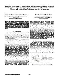
Figure 2: Time courses of Vm,i for with and without dynamic noise.
Figure 1: (a) Subthreshold neuron circuit and (b) network circuit consisting of three noisy neuron circuits and additional 3. Simulation results circuits (M1, M2 and M3) acting as a global inhibitor In the following circuit simulations, we assumed 1.5-µm CMOS process (MOSIS, Vendor: AMIS). First, we simulated the neuron circuit shown in Fig. 1(a) to examine the effect of O(N 2 ) to O(N ) [6] by introducing a global inhibitor, which the random current pulses on the circuit as dynamic noises. facilitates the hardware implementation. The network circuit We assumed that MOS transistors have the same dimension consists of the noisy neuron circuits and additional MOS cir- of W/L = 1.6µm/4µm, except for MOS transistors in curcuits (M1, M2 and M3) implementing the global inhibitor. rent mirrors (W/L = 16µm/4µm). The external analog inWe employ three neurons (N = 3) to achieve small de- put current (Ii ) and the reference current (Iref ) were set to vice sizes and minimum power consumption. Current out- 1 nA. The capacitances (C1 and C2 ) were set to 1 pF, and puts of noisy neuron circuits (Iout,i ) are summed by M1. The the inhibitory input voltage (VI,i ) was set to zero. The ransummed current is mirrored by a current mirror (M1 and M2) dom current pulses Id,i obeying the Poisson distribution (the with a mirror ratio of ∑31:K. Therefore, the output current mean and variation λ = 5000) were generated with an ampli(iout ) is given by K i=1 Iout,i . Since M3 in Fig. 1(b) and tude of 1 nA and the pulse width of 10 µs. Figure 2 shows M2 in Fig. 1(a) forms a current mirror, membrane potentials the time courses of membrane potentials of noiseless (Id,i = (Vm,i for all i) are decreased when iout is increased, which 0) and noisy (Id,i 6= 0) neurons. In Fig. 2(a), we observed results in the global inhibition of all the neuron circuits. periodic oscillation of Vm,i , whereas nonperiodic oscillation To embed the random synaptic weights (static noises) of was observed in Fig. 2(b) because the phase was randomly inMar’s neural network, we introduced nonuniform input cur- creased by the random current pulses (Id,i ). Since the neuron rent Ii for each neuron. Instead of implementing random reset circuit produces spike outputs (Iout,i ) when Vm,i is suddenly of the membrane potential of Mar’s neural network, we intro- decreased, the operation shown in Fig. 2(b) is equivalent to duced dynamic noises by random current pulses (Id,i ), whose randomly resetting the membrane potential after the neuron’s inter-spike-intervals (ISIs) obey the Poisson distribution, for firing. nodes Vm,i and Ui . The oscillation phase of Mar’s network Here, we describe how to determine the inhibitory connecis increased by resetting the membrane potential, whereas tion strength K. Since a network with large values of K inthat of the proposed circuit is increased by the current pulses hibits neurons severely, neurons with small inputs can not sur(Id,i ). Therefore, applying random current pulses to nodes vive [3]. Therefore we have to choose an appropriate K for Vm,i and Ui is qualitatively the same as the random reset in which all neurons can survive. Through our circuit simulaMar’s original network. tions, we found that all neuron could survive when K ≤ 3.
iout (nA)
K=1
0 10-3
K=2
neuron index
0 10-3
K=3
2
1
{
0 3 2 1
[
spike train
10
12
14
16
0 0
1
2 3 τ (ms)
4
5
Figure 3: Auto correlation functions of output of network circuit when inhibitory connection strength K = 1, 2, and 3.
To determine the best value of K, we evaluated the performance of the PDM circuit. As described in Sect. 1, the PDM circuit produces an output spike density that depends only on the intensity of inputs in the ideal case. In other words, the PDM circuit produces spikes periodically when the inputs is constant. Therefore, we set K so that the outputs of the circuit had high periodicity. Since the auto correlation function (ACF) can quantify the periodicity of the output, it is appropriate to determine the performance of the circuit by calculating ACFs. Because the performance of Mar’s model is increases in proportion to K [3], we expected that the most appropriate value of K that is 3 or less would be 3 in order to acquire the best performance. We calculated ACFs of quantized iout [≡ V (t)] where iout was quantized to 0 (or 1) when iout was smaller (or larger) than 0.8 nA, for K = 1, 2 and 3. Figure 3 shows the results for the ACFs with α(τ ) = hV (t0 )V (t0 − τ )i. As K increased, correlation peaks appeared and apparent periodicity was observed when K = 3. Therefore, we set K = 3 where all neurons survive and the highest periodicity is observed. Figure 4 compares the network circuit operations when K = 0 (uncoupled) and K = 3 (coupled). When K = 0 [Fig. 4(a)], iout exhibited nonperiodic oscillations. Noisy neuron circuits fired incoherently. (See raster plots in the figure. Symbols +, × and ∗ represent the firing events of the first, second and the third neuron circuits, respectively.) The resulting ISIs of output spike trains were random. On the other hand, when K = 3, iout exhibited almost periodic oscillations [Fig. 4(b)]. The raster plots in the figure show significant differences between firing frequencies of three noisy neuron circuits as compared to the raster plots in Fig. 4(a). The resulting ISIs of output spike trains were almost uniform, as expected. Figure 5 shows ISI histograms of the uncoupled (K = 0)
18 20 time (ms)
22
24
26
(a) uncoupled network (K = 0)
2
iout (nA)
α(τ) α(τ) α(τ)
10-3
neuron index spike train
1
{
0 3 2 1
[ 0
5
10
15 time (ms)
20
25
30
(b) coupled network (K = 3)
Figure 4: Comparison of network circuit operations when K = 0 (uncoupled network) and K = 3 (coupled network).
and coupled (K = 3) network circuits where 1500 firing events were gathered with ∆ = 0.01 ms. When K = 0, we observed a Poisson-type distribution of ISIs (solid line in Fig. 5) because each neuron circuit was driven by independent noise sources and thus fired incoherently. When K = 3, a Gaussian-type distribution was observed (dashed line in Fig. 5). Once a neuron circuit receiving the maximum external input fires, the network is globally inhibited. After this firing, the neuron circuit operates in its refractory state. Therefore, ISIs of this neuron are higher than in the uncoupled case. Also, the neuron circuit cannot fire when the other neuron circuit receiving a smaller input than the maximum input, fires. Therefore, ISIs of output spike trains follow ISIs of a neuron receiving the maximum input, and the ISIs are averaged over the firing events of all neurons. Figure 6 shows the PSD of the coupled (K = 3) and uncoupled (K = 0) networks with sinusoidal inputs (Ii = I0 + A sin(2πf t), I0 = 1 nA, A = 50 pA, f = 100 Hz) where 16 trials were averaged with a square window function. The measured SNR of the uncoupled network was 10.2 dB, while that of the coupled one was 18.1 dB, which indicated that the noise level of the coupled network was less than one tenth
60 50
K=0
power (a.u.)
40
counts
10-3
uncoupled coupled
K=3
30 20
uncoupled (K = 0) 10-4
coupled (K = 3)
10 0
0
0.2
0.4
0.6 0.8 1.0 time (ms)
1.2 1.4
10-5 1
10
2
10 frequency (Hz)
10
3
10
4
Figure 5: ISI histograms for uncoupled (K = 0) and coupled Figure 6: Power spectra of uncoupled (K = 0) and coupled (K = 3) networks. (K = 3) networks.
of that of the uncoupled network below the cutoff frequency (< 103 Hz). The external random current pulse obeying Poisson distribution is theoretically anti-correlated noise. The change in ISI distributions from the Poisson type to Gaussian type in Fig. 5 implies that the amount of noises was decreased by the effect of the global inhibition. As observed in raster plots in Fig. 4(b), individual neurons fired irregularly and thus seemed not to contribute to the signal transmission between the analog input and the digital (spike) output. Moreover, since the firing order of the neurons was also random, they seemed to fire incoherently. However, the resulting output, the sum of firing events of neurons shown at the bottom of Fig. 4(b), was almost periodic. This mechanism appeared in the resulting PSD (Fig. 6) as noise suppression, which implies that the coupled network is immune to both static and dynamic noises unlike the uncoupled network, which critically depends on the noise characteristics of individual neurons. 4. Conclusion
tion of ISIs. Through circuit simulations we confirmed that the signal-to-noise ratio of a coupled network was improved by 7.9 dB compared with that of an uncoupled one as a result of noise shaping. References [1] M, Hovin, D. Wisland, Y. Berg, J. T. Marienborg, and T. S. Lande, “Delta-sigma modulation in single neurons,” in Proc. of 2002 IEEE International Symposium on Circuits and Systems, vol. 5, 617-620, 2002. [2] S. R. Norsworthy, R. Schreier, and G. C. Temes, ed., Delta-Sigma Data Converters, IEEE Press, Piscataway, NJ, 1997. [3] D. J. Mar, C. C. Chow, W. Gerstner, R. W. Adams, and J. J. Collins, “Noise shaping in populations of coupled model neurons,” Neurobiology, 96, pp. 10450-10455, 1999.
[4] T. Asai, Y. Kanazawa, and Y. Amemiya, “A subthreshold MOS neuron circuit based on the Volterra system,” IEEE We investigated a possible way to develop a one-bit analogTrans. Neural Networks, vol. 14, no. 5, pp. 1308-1312, to-digital converter in a noisy environment. We proposed 2003. a network circuit inspired by neuromorphic architectures to subtly utilize static and dynamic noises in VLSIs. We em- [5] E .A. Vittoz, “Micropower techniques,” in Design ployed a population model of spiking neurons [3]. This model of MOS VLSI Circuits for Telecommunications, Y. Tsihas a network using inhibitory coupling that exhibits noise vidis and P.Antognetti, Ed. Prentice-Hall, NJ:Englewood shaping. We implemented this model with subthreshold MOS Cliffs, 1985, pp. 104-144. circuits to actively employ noise. The static and dynamic noise applied to the circuit for noise shaping were obtained [6] T. Asai, M. Ohtani, and H. Yonezu, “Analog integrated circuits for the Lotka-Volterra competitive neural netfrom device mismatches of current sources and externally apworks,” IEEE Trans. Neural Networks, vol. 10, no. 5, plied random (Poisson) spikes, respectively. A coupled netpp. 1222-1231, 1999. work produced a Gaussian-like distribution of inter-spike intervals (ISIs), while an uncoupled one had a broad distribu-