University of California, Irvine, CA 92697. {dongwans,gerstl, deomer, gajski}@cecs.uci.edu. Abstract: Much effort ..... Kluwer Academic Publishers, January 2000.
AN INTERACTIVE DESIGN ENVIRONMENT FOR C-BASED HIGH-LEVEL SYNTHESIS Dongwan Shin, Andreas Gerstlauer, Rainer D¨ omer, Daniel D. Gajski Center for Embedded Computer Systems University of California, Irvine, CA 92697
{dongwans,gerstl, deomer, gajski}@cecs.uci.edu Abstract:
1.
Much effort in RTL design has been devoted to developing “push-button” types of tools. However, given the highly complex nature, and lack of control on RTL design, push-button types of synthesis is not accepted by most designers. Interactive design space exploration with assistance of tools and algorithms can be more effective because it provides control of all steps of synthesis. In this paper, we propose an interactive RTL design environment, which enables designers to control design steps. In our interactive environment, the user can control the design process at every stage, observe the effects of design decisions, and manually override synthesis decisions at will. Finally, we present a set of experimental results that demonstrate the benefits of our approach. Our combination of automated tools and interactive control by the designer results in quickly generated RTL designs with better performance than fully-automatic results, comparable to fully manually optimized designs.
INTRODUCTION
Automating RTL synthesis is very complicated issue. It is known that the majority of synthesis tasks are NP-complete problems. Hence, the design time becomes large, or the results are suboptimal, resulting designs cannot satisfy the performance or area demands of real-world constraints. To develop a feasible approach for RTL synthesis, we have substituted the goal of a completely automated, “push-button” synthesis system with one that allows to maximally utilize the human designer’s insights. This approach is called Interactive synthesis methodology. In this approach, the designer can control the design process at every stage, Shin, D., Gerstlauer, A., Dömer, R., Gajski, D.D, 2007, in IFIP International Federation for Information Processing, Volume 231, Embedded System Design: Topics, Techniques and Trends, eds. A. Rettberg, Zanella, M., Dömer, R., Gerstlauer, A., Rammig, F., (Boston: Springer), pp. 135–144.
136
Dongwan Shin, Andreas Gerstlauer, Rainer D¨ omer, Daniel D. Gajski
observe the effects of design decisions, and manually override synthesis decisions at will. This is facilitated through a convenient graphical user interface (GUI). Hardware description languages (HDLs) such as Verilog HDL and VHDL are most commonly used as input to RTL design. However, system designers often write models using programming languages such as C/C++ to estimate the system performance and to verify the functional correctness of the design, even to refine the design into implementation. C/C++ offers fast simulation as well as a vast amount of legacy code and libraries which facilitate the task of system modeling. To implement parts of the design modeled in C/C++ in hardware using synthesis tools, designers must then manually translate these parts into a synthesizable subset of a HDL. This process is well known for being both time consuming and error prone. Moreover, it can be eliminated completely. The use of C-based languages to describe both hardware and software will accelerate the design process and facilitate the software/hardware migration. Hardware synthesis tools from C/C++ can then be used to map the C/C++ models into logic netlists. The rest of the paper is organized as follows: section 2 shows related work and section 3 introduces our RTL design environment and the program flow of the proposed RTL synthesis tool. Section 4 shows the experimental results. Section 5 concludes the paper with a brief summary.
2.
RELATED WORK
Issues in RTL modeling, RTL design and behavioral synthesis, aka. High-Level Synthesis (HLS), have been studied for more than a decade now [3]. In the recent years, a few projects have been looking at means to use C/C++ as an input to current design flows [4, 6, 16]. Constructs are added to model coarse-grain parallelism, communication and data-types. These constructs can either be defined as new syntactic constructs, hence creating a new language [4]. They can also be implemented as part of a C++ class library [6]. In order to facilitate the mapping of C/C++ models into hardware, several tools exist that automatically translate C/C++ based descriptions into HDL either at the behavioral level or the register transfer level (RTL) [13, 16, 7]. Many automatic synthesis tools (also known as push-button synthesis) have been developed, including Olympus [10], OSCAR [11], SPARK [7], Synopsys Behavioral Compiler [15], Mentor Catapult-C [12], and Cyber [16]. However, these tools provide no means to access the interme-
An Interactive Design Environment for C-based High-Level Synthesis
137
Bus Functional Model
Preprocessing
Performance Analysis
RTL Library
Super FSMD
Algorithms
GUI
Design decisions Performance Analysis
RTL Refinement
Cycle-accurateFSMD
Netlist Mapper
Structural RTL
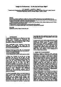
Figure 1.
RTL design flow
diate design models that are created during the synthesis process and to change important decisions by designers. The designer can specify design constraints for whole designs and access the behavioral input model and the structural output model and design constraints. Some interactive synthesis approaches [8, 9] addressed the importance of user-interaction with synthesis system. However they have a fixed design flow, that is, the designer has to perform a sequence of synthesis tasks in a predefined order and a cycle-accurate simulation model with complex components is not available for the intermediate stages.
3.
RTL DESIGN ENVIRONMENT
In this section, we will describe our RTL design environment integrated in a system-level design flow. The RTL design environment provides synthesis, refinement and exploration for RTL design as shown in Figure 1. It includes a graphical user interface (GUI) and a set of tools to facilitate design flow and perform refinement steps. In our flow, designers or algorithms of automatic tools can make decisions such as clock period selection, allocation, scheduling and binding. The GUI allows designers to input and change such design decisions. It also enables the designer to observe the effects of the decisions and to manually override the decisions at will. Further, the designers can make partial decisions and then run automatic tools to take care of the rest of the decisions. We model an RTL design as a Finite State Machine with Data (FSMD) [1], which is an FSM model with assignment statements added to each state. The FSMD can completely specify the behavior of an arbitrary
138
Dongwan Shin, Andreas Gerstlauer, Rainer D¨ omer, Daniel D. Gajski
RTL design. The variables and functions in the FSMD may have different interpretations which in turn defines several different styles of RTL semantics. In addtion, in order to represent pipelined or multicycled units in a design in the cycle-accruate FSMD, we have introduced new constructs [2] such as piped for pipelined units, and after for multicycle units. The simulation speed of the cycle-accurate FSMD is significantly improved compared with that of the structural RTL description. During preprocessing, the behavioral description of custom hardware in C/C++ will be refined into an SFSMD model where each state is a basic block of the original description. Also some presynthesis optimization techniques including constant propagation, dead code elimination, and common subexpression elimination are integrated. The generated FSMD will be the input model of the RTL synthesis. A performance analysis tool is used to obtain characteristics of the initial design such as the number of operations, variables and data transfers in each state, which serves as the basis for RTL design exploration. It also produces quality metrics for RTL design such as the delay and power of each state and area of the design to help the designers to make decisions on clock selection, allocation, scheduling and binding. The refinement tool then automatically transforms the FSMD model based on relevant design decisions. Finally, the structural RTL model is produced by a netlist mapper, ready to feed into traditional design tools for logic synthesis, etc.
3.1
Synthesis Decisions
The refinement engine works on directions called the RTL synthesis decisions. The synthesis process can either be automated or interactive as per the designer’s choice. However, the decisions must be input to the refinement engine using a specific format. For the purpose of our implementation, we annotated the input model with the set of synthesis decisions. The refinement tool then detects and parses these annotations to perform the requisite model transformations. Based on these decisions, the refinement engine imports the required RTL components from the RTL component library and generates the cycle-accurate FSMD. The decisions can be made by designers interactively through GUIs and/or be made through automatic algorithms. The GUIs for interactive decision-making allows designers to (a) specify decisions (b) override the decisions, which are already made by the designers or automatic algorithms (c) partially assign decisions and automatic algorithms will fill in the rest of decisions.
An Interactive Design Environment for C-based High-Level Synthesis
139
The GUI also allows automatic algorithms being plugged in. Thus it is easily extendible because designers can select an algorithm from a list of plug-in algorithms such as ASAP, ALAP, list and force-directed scheduling and graph coloring for binding and so on. Resource Allocation Table Instance alu0 alu1 mult0 mac0 rf0 mem0 bus0 bus1 bus2 bus3
Type
Width
Area
Delay
Stages
Cost
32 bits 528 12.3ns 0 $1 ALU 32 bits 528 12.3ns 0 $1 MULT 32 bits 16803 15.2ns 2 $12 32 bits 20142 15.3ns 2 $14 MAC 32 bits 21452 RTL2.4ns $16 RF Unit Selection0 32 bits 80242 32.8ns 0 $6 SRAM Categories 32 bits Type Width Area Delay Stages 34 2ns 0 $1 32 bits 34 2ns 0 $1 ALU Functional Unit 32 bits 2ns528 12.3ns 0 BUS 32ADDER bits 34 0 $1 32 bits 2ns211 10.2ns 0 bits 34 0 $1 Register File 32ADD/SUB 32 bits 258 10.8ns 0 Bus MULT 32 bits 16803 15.2ns 2 Memory MAC 32 bits 20412 15.3ns 2 Register
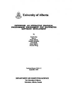
Figure 2.
... … … … … … … Cost … … $1… $1… $1 $12 $14
... … … … … … …
Allocation window
3.1.1 GUI for Interactive Decision-making. In order to help designers to make synthesis decisions interactively, we provide an allocation window and a scheduling & binding window. In allocation window as shown in Figure 2, designer can see all RTL components in the RTL component library, select them and set the parameters such as bit width, size of array and so on [5]. The scheduling & binding window displays the SFSMD in state-operations table format which contains a series of states, each state containing a set of operations to be performed in the state, shown in Figure 3. The state-operations table displays the behavior of a design and all design decisions made in graphical format. This is, the designer can modify all design decisions at any time in the design process in the state-operations table. In the table, State is the current state and NS is next state. CS is the control step of the expression which is relative to the start time of the state. The table also shows statistics such as the lifetimes of all variables, occurrences of operations, the number of data transfers and the critical path in number of operations in each state. It also shows the ASAP and ALAP control step for each expression in each state. All expressions are scheduled at specified control steps in the scheduling view, which will be assigned to CS in the state-operations table. All operations are bound to functional units and their ports, which will be specified in the oper column. Also all operand variables (destination, source1, source2 ) are mapped to storage units, read/write ports of the
140
Dongwan Shin, Andreas Gerstlauer, Rainer D¨ omer, Daniel D. Gajski State Operations Table State
NS
destination
oper
source1
source2
0
O1
+
I1
I2
S1 S1 S2 S2
Estimation
CS
S1
1
O2
*
I1
O1
2
_status_