International Journal of Computer Science & Information Technology (IJCSIT) Vol 7, No 1, February 2015. DOI:10.5121/ijcsit.2015.7110. 93. AN ITERATIVE ...
International Journal of Computer Science & Information Technology (IJCSIT) Vol 7, No 1, February 2015
AN ITERATIVE MORPHOLOGICAL DECOMPOSITION ALGORITHM FOR REDUCTION OF SKELETON POINTS 1
Dr. A. Sri Krishna,
2
G. L. K. Vasista, 3N. Neelima.
1,3
2
Dept. of IT, R.V.R& J.C College of Eng. Guntur, India. Dept. of CSE, AMRITA School of Eng., Coimbatore, India.
ABSTRACT Shape representation is an important aspect in image processing and computer vision. There are several skeleton transforms that lead to morphological shape representation algorithm. One of the main problems with these algorithms is in selecting the skeleton points that represent the shape component. If the numbers of skeleton subsets are reduced then the reconstruction process will be easy and time consuming. The present paper proposes a skeleton scheme that selects skeleton points based on the largest shape element. By this, overall skeleton subsets will be reduced. The present method is applied on various images and is compared with generalized skeleton transform and octagon-generating decomposition algorithm.
KEYWORDS Skeleton subsets, Reconstruction, Shape component, Structuring element, Shape representation.
1. INTRODUCTION Shape description and analysis is a fundamental problem in image processing and pattern recognition [1][2]. Good shape representation or description schemes not only are important in developing shape analysis algorithms for shape matching and recognition tasks[6], they also are important in developing efficient coding schemes for data compression purposes[8] and developing video compression and image data retrieval algorithms. Certain properties of a shape representation scheme are desirable. A good shape representation should have well defined mathematical characterizations. The representation should be generated according to simple, precise, and meaningful rules, instead of depending on some arbitrary decisions. A well-defined representation is more likely to capture the intrinsic characteristics of a given shape explicitly. A good shape representation should provide an accurate and complete description of the given shape. The original shape should be allowed to be easily reconstructed or approximated. A good shape representation should be compact. Efficient manipulation of the shape representation should be possible. A good shape representation should be easily computed. Computational efficiency is always a desirable feature in a computer imaging system. A number of shape representation schemes have been developed over the years. Structural shape description is one of them. In a structural shape description, a shape is first decomposed into a number of shape components or primitives. The given shape is represented in terms of these simpler components and the relationships among them. In recent years, a number of morphological shape representation and decomposition algorithms have been proposed [8]-[14]. Mathematical morphology is a shape-based approach to image processing [5] [6]. One advantage of mathematical morphology is that basic morphological operations can be implemented very efficiently on many parallel image computers [7]. Another advantage of mathematical DOI:10.5121/ijcsit.2015.7110
93
International Journal of Computer Science & Information Technology (IJCSIT) Vol 7, No 1, February 2015
morphology is that it has a well-developed mathematical structure, which provides a foundation for the analysis of morphological image processing algorithms. In a recent paper [15], a generalized skeleton transform (GST) was introduced that derives generalized skeleton points for a given shape image. Each skeleton point represents a generalized maximal “disk,” which, in general, is an octagon. The main advantage of the generalized skeleton transform is that iteads to an efficient shape decomposition scheme. In this scheme, a given shape is decomposed into a collection of modestly overlapping octagonal shape components. These octagonal components are more primitive than the components obtained from the morphological shape decomposition (MSD) or overlapped morphological shape decomposition (OMSD) [9]. Each octagonal component is represented by a single center point and the overlapping level is reduced. However, one problem with this decomposition scheme is that the GST needs to be applied multiple times. Another problem is that although it is easier to compare two octagons than to compare two shape components from the MSD or OMSD, it is still not a trivial task to define a meaningful similarity measure for such octagonal components. In the recent paper [16], octagonfitting algorithm (OFA) is defined that finds a special maximal octagon for each image point of a given shape. The OFA has allowed us to develop two new shape decomposition algorithms. The first decomposition algorithm will use octagonal shape components octagon-generating decomposition (OGD) algorithm and the second disk-generating decomposition (DGD) algorithm. However, the OFA will only need to be applied once. Recently new algorithms for skeletonization and thinning, for 2D images based on primitive concept approach were proposed [17]-[19]. The paper is organized as follows: The methodology is introduced in section 2. Section 3 contains experimental results and some discussions. Concluding remarks are given in section 4.
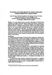
2. METHODOLOGY The skeleton points that participate in the reconstruction of the image are called the skeleton subset. One needs to store skeleton subsets for reconstruction of the image. The present paper aims to remove redundant skeleton subsets. Any shape reconstruction algorithm can be represented as the Block Diagram shown in Figure 1.The skeleton points are generated using skeleton point generation algorithm. However all these skeleton points are not required for the reconstruction of the image. The present paper proposes an efficient algorithm for the selection of skeleton subsets for reconstruction of the image. The algorithm uses the sequence of eight structuring elements in the following order: B , B ,... B , B , B ,... B , B , B ,... .The structuring element is in . Figure 2. 0
Original shape element
skelet on point gener ation
1
7
Select ion of skelet on points
0
1
7
0
1
Recon structi on of shape
Fig. 1.Block diagram of Shape reconstruction
Fig.2 Structuring Elements.
94
International Journal of Computer Science & Information Technology (IJCSIT) Vol 7, No 1, February 2015
Algorithm1: Skeleton Points Generation. 1. 2. 3. 4. 5. 6. 7. 8. 9. 10. 11. 12. 13. 14. 15. 16. 17.
18. 19.
Read an Input image X1 of size a x b. Define Eight Structuring elements S1,S2……S8. Initialize an array SK[1:8] to zero, and b1 to 1. Convert the Input image X1 to a binary image X. Erode the binary image X with S1 Structuring element and store it in an array T. If T is Empty go to step10. Sk[b1]=SK[b1]+1. If T does consists of Isolated points Push the array Ton to the stack and go to step 10 Store the Isolated points in an 3D array Y and it corresponding Structuring element in an array S Find the difference between X array and T array and store in array Z. If Z is Empty go to step 14. If Z does consists of Isolated points Push the array Ton to the stack and go to step 14. Store the Isolated points in an array 3D Y and it corresponding Structuring element in an array S If stack empty go to 19. Pop the image from Top of the stack and store it in X. Calculate b1=mod(b1+1,8) Switch(b1) Case 1: Erode X with S1 and store it in array T Break; Case 2: Erode X with S2 and store it in array T Break; Case 3: Erode X with S3 and store it in array T Break; Case 4: Erode X with S4 and store it in array T Break; Case 5: Erode X with S5 and store it in array T Break; Case 6: Erode X with S6 and store it in array T Break; Case 7: Erode X with S7 and store it in array T Break; Case 8: Erode X with S8 and store it in array T Break; Go to step 6. End.
The present paper selects the skeleton points from above algorithm.To reduce overlapped skeleton points , the proposed paper outlines a new algorithm called Skeleton point reduction decomposition(SRD). The present algorithm defines a size relation between any two final shape elements represented by two skeleton points in the following way. If the two skeleton points belong to the same final subset, then they represent two final shape elements of the same shape. Obviously, they have the same size and the two image points cannot be adjacent to each other. If they belong to two different final subsets, then there must be an erosion step. The eroded subset is called Y set and the other will be called as the Z set. The Y set defines the larger shape element than the other. This is due to the erosion step of the reduction process. The proposed algorithm takes each skeleton point and does the summation of corresponding structuring elements and takes largest value as the first shape element. The first shape component in the structural representation is the largest final shape element. The second shape component is 95
International Journal of Computer Science & Information Technology (IJCSIT) Vol 7, No 1, February 2015
the largest shape element with its center outside the first shape component. This condition ensures that each shape component covers a significant new area of the given shape and only modest overlapping is allowed. The same selection process is repeated until all the image points are covered. The complete process of selecting the final shape element is given in the Algorithm2 as skeleton point reduction decomposition (SRD) algorithm. Algorithm2: Skeleton point reduction decomposition (SRD). 1. Read N i.e. Number of skeleton point subsets from the Algorithm to generate skeleton points. 2. Sum(i) SE(i, j) N
N
i 1
i 1 j 1
8
3. Arrange the Array Sum in decreasing order. 4. Arrange the skeleton point subsets and corresponding structuring elements in the decreasing order of their Sums. 5. Select the first skeleton point subset and initialize I=1 and K=1. 6. Take an Array A and store the x and y coordinate of the skeleton points and corresponding eight structuring elements by incrementing index K. 7. Initialize Array X with zeros of size of the image to store shape component. Place 1 at the x and y coordinate of the skeleton points and dilate with corresponding structuring element. 8. Increment I=I+1, Take the skeleton point subset with index I and check the position of first isolated points from the set of skeleton points. 9. If (position (x, y) is with in shape X) go to step 8. 10. Increment K=K+1, store the x and y coordinate of the skeleton points and corresponding eight structuring element by incrementing index of K. 11. Initialize Array B with zeros of the size of image to store temporary shape component. Place 1 at the x and y coordinate positions of the skeleton points and dilate with corresponding structuring element. 12. Add Array B to Array X i.e. (X contains shape components). 13. If ( I N ) Go to 8. 14. Array A consists of selected skeleton point subsets and the corresponding structuring element. Algorithm3: Reconstruction of image. A given shape is reconstructed using the following formula: (3)
X Ni1 Ci D
Where N is the number of skeleton points subsets selected from the skeleton point reduction decomposition (SRD) algorithm Ci is the set of centers of the representative disks and D(i.e. B B .... B ... B ... )is the combination of the basic structuring elements used to derive X. 0
1
7
0
3. R ESULTS AND DISCUSSIONS The present method is applied on different images i.e.(a) teapot;(b) lamp; (c) telephone; (d) dog; (e) digits; (f) letters;(g) fish; (h) butterfly; (i) Telugu character which represent different shapes as shown in Figure 3. The reconstructed images using generalized skeleton transform (GST), octagon-generating decomposition (OGD) and present skeleton point reduction decomposition (SRD) algorithms are shown in Figure 4, 5 and 6 respectively. One problem with any generalized morphological skeleton transform is after decomposition they generate noise. To overcome this single noise removal algorithm “Median Filter” of size 3X3 is applied on the reconstructed images of GST, OGD and SRD and they are shown in Figure 7, 8, and 9 respectively. Sometimes by reversing the background color there will be a change in reconstructed images due to overlapping of dilation operation. To estimate this effect the present 96
International Journal of Computer Science & Information Technology (IJCSIT) Vol 7, No 1, February 2015
paper generated all nine images by reversing the background color as shown in Figure 10. The GST, OGD and SRD algorithms are applied on all nine images and the reconstructed images are shown in Figure 11, 12 and 13 respectively. A noise filter is applied on the Figure 11, 12 and 13 images to reduce the noise effect and resultant reconstructed images for GST, OGD, and SRD are shown in Figure 14, 15 and 16 respectively. The generalized skeleton transform, failed in reconstructing the images as shown in the Figure 4 and Figure 11. The size of the reduced skeleton point subsets for all the three methods GST, OGD and SRD algorithms in foreground and background intensities are shown in Table 1 and 2 respectively. The tables clearly indicate the strength of the proposed SRD algorithm over GST and OGD algorithm. After applying noise removal algorithm lot of noise is reduced in all the three methods. Although skeleton subsets are reduced drastically in GST, it failed in reconstruction stage of several images. The some of the reconstructed images by GST are difficult to recognize. This is clearly evident from Figure 11(a), 11(e) and 11(f) and also from Figure 14(a), 14(e) and 14(f). Moreover GST has completely failed in reconstruction of the images when background intensity is reversed. This fact is evident from Figure 4 and Figure 7. This is due to an abnormality caused by the discrete nature of the algorithm. And the aim of any algorithm in reducing skeleton subsets must be to obtain a good reconstructed image component. Though in few cases (roughly 10%) the OGD algorithm produces good reconstructed image than the SRD algorithm but the numbers of skeleton subsets of OGD are higher than the proposed SRD algorithm. This clearly indicates the SRD algorithm can be used in applications like Broadcast TV, Video conferencing and Facsimile transmission where the error rate is tolerated.
Fig. 3.Shape images used in the experiments: (a) teapot;(c) telephone;(d) dog; (e) digits; (f) letters; (g) fish;(h) butterfly; (i) telugu character
Fig. 4.Shape images after reconstruction using GST Algorithm (a)teapot; (b)lamp; (c)telephone; (d)dog; (e)digits; (f)letters; (g)fish; (h)butterfly; (i)telugucharacter 97
International Journal of Computer Science & Information Technology (IJCSIT) Vol 7, No 1, February 2015
Fig. 5.Shape images after reconstruction using OGD Algorithm (a)teapot; (b) lamp;(c)telephone; (d) dog; (e) digits; (f) letters; (g) fish; (h) butterfly; (i) telugu character.
Fig. 6.Shape images after reconstruction using SRD Algorithm (a)teapot; (b)lamp; (c)telephone; (d)dog; (e)digits; (f)letters; (g)fish; (h)butterfly; (i)telugu character.
Fig. 7.Shape images after reconstruction using GST Algorithm and application of median filter (a)teapot; (b)lamp; (c)telephone; (d)dog; (e)digits; (f)letters; (g)fish; (h)butterfly; (i)telugu character
98
International Journal of Computer Science & Information Technology (IJCSIT) Vol 7, No 1, February 2015
Fig.8. Shape images after reconstruction using OGD Algorithm and application of median filter(a) teapot; (b)lamp; (c)telephone; (d)dog; (e)digits; (f)letters; (g)fish; (h)butterfly; (i) telugu character
Fig. 9.Shape images after reconstruction using SRD Algorithm and application of median filter (a)teapot; (b)lamp; (c)telephone; (d)dog; (e)digits; (f)letters; (g)fish; (h)butterfly; (i)telugu character.
Fig.10.Shape images used in the experiments(with foreground and background reversed)a) teapot; (b)lamp; (c)telephone;(d) dog;(e) digits; (f) letters;(g) fish; (h) butterfly; (i) telugu character. 99
International Journal of Computer Science & Information Technology (IJCSIT) Vol 7, No 1, February 2015
Fig. 11.Shape images after reconstruction using GST Algorithm (a)teapot; (b)lamp; (c)telephone; (d)dog; (e)digits; (f)letters; (g)fish; (h)butterfly; (i)telugu character Table 1. Numbers of Components Used by Different Decomposition Algorithms to Represent Nine 70 70 Shape Images
GeneralizedSkeleton Algorithm
OctagonalGenerating Decomposition Algorithm
Skeleton point Reduction Decomposition Algorithm
Teapot
38
190
103
Lamp
29
203
101
Telephone
40
165
101
Dog
39
235
116
Digits
-
193
115
Letters
35
227
132
Fish
41
173
92
Butterfly Telugu characters
39
257
119
47
146
110
Fig. 12.Shape images after reconstruction using OGD Algorithm (a)teapot; (b)lamp; (c)telephone; (d) dog; (e) digits; (f) letters; (g) fish; (h) butterfly; (i) telugu character
100
International Journal of Computer Science & Information Technology (IJCSIT) Vol 7, No 1, February 2015
Fig. 13.Shape images after reconstruction using SRD Algorithm (a)teapot; (b)lamp; (c)telephone; (d)dog; (e)digits; (f)letters; (g)fish; (h)butterfly; (i)telugu character
Fig. 14..Shape images after reconstruction using GST Algorithm and application of median filter (a)teapot; (b)lamp; (c)telephone; (d)dog; (e)digits; (f)letters; (g)fish; (h)butterfly; (i)telugu character.
Fig. 15. Shape images after reconstruction using OGD Algorithm and application of median filter (a) teapot; (b)lamp; (c)telephone; (d)dog; (e)digits; (f)letters; (g)fish; (h)butterfly; (i) telugu character.
101
International Journal of Computer Science & Information Technology (IJCSIT) Vol 7, No 1, February 2015
Fig. 16.Shape images after reconstruction using SRD Algorithm and application of median filter (a)teapot; (b)lamp; (c)telephone; (d)dog; (e)digits; (f)letters; (g)fish; (h)butterfly; (i)telugu character. Table.2. Numbers of Components Used by Different Decomposition Algorithms to Represent Nine 70 70 Shape Images (with foreground and background inverted).
GeneralizedSkeleton Algorithm
OctagonalGenerating Decomposition Algorithm
Skeleton point Reduction Decomposition Algorithm
Teapot
26
78
74
Lamp
31
110
87
Telephone
38
173
137
Dog
31
114
86
Digits
36
82
52
Letters
31
77
73
Fish
38
133
121
Butterfly
38
105
106
Telugu characters
39
115
89
4. CONCLUSIONS In this paper we have introduced a Skeleton point Reduction Decomposition (SRD) algorithm. Using this method, the numbers of skeleton subsets are reduced. However, by comparing GST, the numbers of skeleton subsets are more. But GST failed completely in representing some of the images. The present paper concludes that GST fails in reconstruction of some shapes and fails completely if we reverse the background color. The number of skeleton subsets is reduced by the proposed algorithm when compared with OGD. Hence the present paper concludes that the proposed SRD algorithm is better than GST and OGD. The extra noise generated in reconstruction of the image can easily be removed by applying simple noise filters.
102
International Journal of Computer Science & Information Technology (IJCSIT) Vol 7, No 1, February 2015
REFERENCES [1] [2] [3] [4] [5] [6] [7] [8] [9] [10] [11] [12] [13] [14] [15]
[16] [17] [18]
[19]
L.G.Shapiro, “A structural model of shape,” IEEE Trans. Pattern Anal.Machine Intell., vol. PAMI-2, 111–126, (1980). S.Loncaric, “A survey of shape analysis techniques,” Pattern Recognit., vol. 31, no. 8, 983–1001, (1998). P.E. Trahanias, “Binary shape recognition using the morphological skeleton transform,” Pattern Recognit., vol. 25, no. 11, 1277–1288,(1992). R.Kresch and D. Malah, “Skeleton-based morphological coding of binary images,” IEEE Trans. Image Processing, vol. 7, 1387–1399, Oct. (1998). J.Serra, Image Analysis and Mathematical Morphology. London, U.K.: Academic, (1982). R.M. Haralick, S. R. Sternberg, and X. Zhuang, “Image analysis using mathematical morphology,” IEEE Trans. Pattern Anal. Machine Intell., vol. PAMI-9, no. 4, 532–550, (1987). J.Xu, “Decomposition of convex polygonal morphological structuring elements into neighborhood subsets,” IEEE Trans. Pattern Anal. Machine Intell., vol. PAMI-13, no. 2, 153–162, (1991). P.A. Maragos and R. W. Schafer, “Morphological skeleton representation and coding of binary images,” IEEE Trans. Acoust., Speech, Signal Processing, vol. 34, no. 5, 1228–1244, (1986). I.Pitas and A. N. Venetsanopoulos, “Morphological shape decomposition,” IEEE Trans. Pattern Anal. Machine Intell., vol. 12, no. 1, 38–45, (1990). J.Xu, “Morphological representation of 2-D binary shapes using rectangular components,” Pattern Recognit., vol. 34, no. 2, 277–286, (2001). J.Xu, “Morphological decomposition of 2-D binary shapes into convex polygons: A heuristic algorithm,” IEEE Trans. Image Processing, vol. 10, 61–71, Jan. (2001). A.Held and K. Abe, “On the decomposition of binary shapes into meaningful parts,” Pattern Recognit., vol. 27, no. 5, 637–647, (1994). C.Ronse and B. Macq, “Morphological shape and region description,” Signal Process., vol. 25, 91– 106, (1991). J.Goutsias and D. Schonfeld, “Morphological representation of discrete and binary images,” IEEE Trans. Signal Processing, vol. 39,1369–1379, June (1991). J.Xu, “A generalized discrete morphological skeleton transform with multiple structuring elements for the extraction of structural shape components,” IEEE Trans. Image Process., vol. 12, no. 12, 1677– 1686, Dec. (2003). J.Xu, ”Morphological decomposition of 2-D binary shapes into modestly overlapped octagonal and disk components” IEEE Transactions On Image Processing, vol. 16, no. 2, 337-348, (2007). V.Vijaya Kumar, A.Srikrishna, D.V.L.N.Somayajulu, B.Raveendra Babu, “An improved iterative morphological decomposition approach for image skeletonization,” GVIP Journal,volume 8,issue 1,47-54,June, (2008). V.Vijaya Kumar, A.Srikrishna, Sadiq Ali Shaik, S.Trinath“A new skeletonization method based on connected component approach,” International Journal of Computer Science and Network Security, vol.8 no.2, 133-137, (2008). V.Vijaya Kumar, A.Srikrishna, B.Raveendra Babu, “A comparison on morphological skeleton transform with multiple structuring elements,” International conference ICORG 2006 held from to june, at NIRD campus, Hyderabad.
Authors Dr. A. Sri Krishna received the PhD degree from JNTUK, Kakinada in 2010, M.Tech degree in Computer Science from Jawaharlal Nehru Technological University (JNTU) in 2003, M.S degree in software systems from Birla Institute of Technology and Science, Pilani in 1994, AMIE degree in Electronics & communication Engineering from Institution of Engineers, Kolkata in 1990. She has 23 years of teaching experience as Assistant Professor, Associate Professor, Professor and presently she is working as a Professor and Head, Dept of Information Technology at RVR&JC College of Engineering, Guntur. She has published 15 papers in International/ National Journals and Conferences. Her research interest includes Image Processing and Pattern Recognition. She is member of IE(I) and member of CSI.
103
International Journal of Computer Science & Information Technology (IJCSIT) Vol 7, No 1, February 2015 G L K Vasista Pursuing his B.Tech Graduation in computer science and engineering in Amrita School of Engineering, Coimbatore, India. He has been actively participating and presenting papers in student technical Symposium seminars at National Level. His area of interest includes Image Processing, Data Structures and Algorithms, Networks and Web Technology. .
N.Neelima received masters degree M.Tech(CSE) from Acharya Nagarjuna University in the year 2007, Guntur. She has 7 years of teaching experience. Presently she is working as an Assistant Professor in Department of IT, RVR & JC College of Engineering and she is pursuing Ph.D from JNTUH, Hyderabad. Her research interest includes Image and Signal Processing and computer vision. She is a member of IAENG.
104