ObJect-oriented programming environments provide a powerful means of modeling real-world items In a way which is more attractive than the earlier ...
EEE TRANSACTIONS ON MAGNETICS, VOL. 29, NO. 2, MARCH 1993
1939
An Object-Oriented Representation of Electromagnetic Knowledge Dhammika Kurumbalapitiyaand S. Ratnajeevan H. Hoole Department of Engineering, Harvey Mudd College, Qaremont, CA 91711. ObJect-oriented programming environments provide a powerful means of modeling real-world items In a way which is more attractive than the earlier programming paradigms. Applicatlons In areas such as the development of knowledge based systems for engineering design are enhanced by using obJect-oriented programming techniques. Therefore the use of obJect-oriented programmlng techniques in developing a program and a relatively small knowledge-base of electromagnetic concepts, analytical tools, heuristics and devices is presented. How such an Integration provides a true 8utomated environment for devlce synthesis and design, is also described.
A bsfruct:
1INTRODUON
The use of computers in engineering electromagnetics is mainly in the areas of solving complex mathematical equations either numerically or symbolically. Device synthesis and design are still performed by experts in the field and they use computers as an analytical tool [l].The design of a device usually starts with an initial guess that satisfies the design goals approximately. Then analysis programs are used upon these initial configurations to obtain the corresponding field solution, If the results match with the goals then the process is stopped; otherwise the initial guess is modified repeatedly until a proper solution is attained [2]. This process is supported and/or guided by a range of human intelligence such as understanding figures of field solutions. predicting field solutions under parameter variations and/or configuration changes and suggesting a certain configuration or parameter distribution to achieve a particular flux distribution or performance criterion [3]. Most of these tasks require a fiim understanding of electromagnetic fields and device characteristics.This understanding is based on both theoretical concepts and experience. Therefore for a computer program to be capable of showing intelligence io these areas where human designers are presently smarter. it must contain both theoretical and experiential knowledge. Some of these intelligent tasks are performed according to well understood algorithms and they are highly procedural. On the other hand the use of the heuristics involved has no precise steps in handling the situation though they produce useful results.
are used in modeling the items found in the electromagnetic domain. Other features such as polymorphism and message passing [4,5]are extensively used by the inference programs. In certain cases state-machine based logic is used in making decisions based on the state of the system.
II SYNTAX AND SEMANTICSCXELECl'ROMAGNEE!S Consider a dictionary being referred to. to find the meaning of an unknown word. Initially only an ordered set of characters is seen. However, one could apply the phonetic rules of the language to pronounce the word but still the meaning is missing. Such a form of the word is purely a syntactic one. Normally the first action behind finding the meaning is to search for an entry in the dictionary that matches exactly with the syntax of the word. If an entry with a p q p r match is found and the description under that entry needs no further reference, then the meaning of the unknown word is understood. Usually the process does not stop here and sometimes the meaning of the word is connected with a personal experience, a theoretical phenomenon and so on. This process of assigning a meaning to any object in a certain domain is called finding the semantics of that object. In mder to use the concept of an object in a specific domain its dependency with the rest of the objects in the domain must be found. Semantic networks, as the term indicates, provide a natural way of representing semantics in a certain domain. The
name of the association is written along the line.
An efficient way of representing these kinds of knowledge in a computer is very important. There are many knowledge representation paradigms in practice today. The approach followed here is based on frames and structured objects [4,5. 61. A frame is capable of representing a stereotypical concept,
event or a physical object in the real-world. Objects too are capable of doing so. In order to represent knowledge in frames, a programming environment designed for that purpose should be found. But in the case of objects a general purpose objectoriented programming (OOP) language will provide rapid prototyping facilities of real world quantities. The main reason for our using objects rather than frames here is the availability of a good object-oriented programming language, namely the Common Lisp Object System (CLOS) [7]. Some of the fundamental concepts in OOP such as data abstraction, inheritance. multiple inheritance and default argument settings
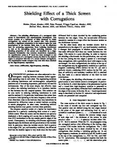
Fig 1: Semantic Network Representing Some Concepts in Electromagnetics-Devices Domain.
0018-9464/93$03.000 1993 IEEE
1940
Many relationships among the concepts represented in the network can be obtained by referring to the associations in the forward and backward directions. For instance, a COAXIAL-CABLE is-a special form of a CONDUCTOR and it has properties similar to all CONDUCTORS as well as some attributes that are unique to it. The key-words in this semantic network are similar to the entries found in a dictionary and they serve as the basic vocabulary and each and every concept found in electromagnetics has a unique place here. Therefore the semantics of the sentence, “Field-Plot of-a Coaxial-Cable” can be found from the network. It is also possible to find the other concepts that contribute in casting a meaning to the same sentence. For instance it does not say that the “COAXIAL-CABLE is-an ELECTRICAL-DEVICE” explicitly but this representation provides a means of deriving this fact and i n h e r i r i n g the properties of an ELECTRICAL-DEVICE. The function of an inference program indeed, is to make facts explicit by referring to implicitly expressed facts. Certain entries in this semantic network do not represent actual physical objects but they help in characterizing common attributes that belong to specific objects. Consider for instance the key-word ELECI‘RICAL-DEVICE. This identifier, in general, does not point out a particular device but it helps in classifying a class of devices. The identificationof such entries is one of the main tasks in object orientation and will be discussed in the coming sections in detail.
In an OOP environment there exists only one kind of entity and it is the object. Real-world concepts are organized as a finite set of discrete software structures although such a discretization maters the smoothness in reality. Objects are created using templates called classes that encapsulate attributes (instance variables) and behavior (methods) of a realworld concept. Therefore objects are known as instances of their underlying classes. Classes are usually arranged in a hierarchical structure and new classes are derived from existing classes by adding new attributes. Any parent class of a newly built class in is known as the super-class and becomes a subclass of the parent class. When a new class is derived from an existing class, it inherits all the attributes and behavior of the existing class and this is one of the fundamental characteristics of OOP.This process is generally known as inheritance and if more than one super-class are involved in forming a new class, it is known as multiple inheritance. It has already been mentioned that certain concepts do not represent actual physical objects though they classify common characteristics of a group of specific objects. Such concepts represent an abstract form of knowledge about the domain. The corresponding entity in OOP is the abstract class which is used as a template not to cast objects but to derive sub-classes. Therefore a good set of abstract classes of a domain will provide a powerful means of prototyping new concepts. Objects interact with each other via sending messages. A message is implemented as a procedure where it hides the internal representation of the attached object. For instance if the message DRAW is sent to an instance of the COAXIAL-CABLE class, it draws the figure of a coaxial cable using its own routines and values. It is also possible to recognize common operations attached to objects such as
JEEE TRANSACTIONS ON MAGNETICS, VOL.29, NO. 2, MARCH 1993
DRAW. Instances of two different classes, of course must respond in two different ways to the command DRAW. In OOP the same syntactic form of a message can take many implementations for objects in different classes. This is known as polymorphism and is one of the most wonderful features of OOP that is being used everywhere in our programs. Finally, it is possible to assign default values for the attributes of objects. Default values or symbolic structures help humans in performing intelligent tasks. For instance, an AC electrical device has a rated voltage of 120 V in the US unless otherwise stated. Therefore in case the rated voltage is not specified this default value will be used. It is important to note here that these default values are not buried in programs like in conventional programming paradigms.
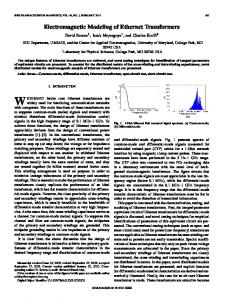
Object oriented modeling of electromagnetic devices requires a firm understanding of both the domain and the modeling methodology [5]. This discussion is focused mainly on the modeling methodology since many powerful concepts available in OOP are found to be useful in reorganizing large software programs written in electromagnetics. Fig.2 gives class definitions of three concepts that appeared in Fig. 1.
I Class Name: ELECTRICAL DEVICE
1
Class Name: COAXIAL-CABLE Super Class:CONDUCTOR
-
I
Insulator Material __
IMethods
-
Inner Conductor Material Sheathhiaterial 1-
1-
I
I
Number of Strands t Connector Type 1B d d o w n Voltage Impedance
i
-... ._ -..
I
I
1
1
Dialog-> Examples->
.....
I
Fig.2: The formation of Electromagnetic Concepts Hierarchy.
The following considerations are made while forming this class hierarchy. In the first place the abstract concepts are identified together with their attributes and behavior. ELECTRICAL-DEVICE is such an abstract class and further, it has not been derived from any existing class. Such a class is named a root class of a class hierarchy and hence it is possible to think of it as a “root concept.” Though many electrical devices’ operation is governed by flux, note here that the concept FLUX appearing in Fig. 1 is not included in the class ELECTRICAL-DEVICE . The reason is that FLUX is
1941
IEEE TRANSACTIONSON MAGNETICS, VOL. 29, NO. 2, MARCH 1993
identified as a root concept where it can stand by its own. The semantic network is the one that supports linking the ELECTRICAL-DEVICE with FLUX.Selecting proper default arguments for the appropriate attributes is done next. Modeling real-world concepts such as items in electromagnetics is a difficult task but a carefully developed set of abstract classes will make future expansions convenient. It is seen that if the present class looses its generalization due to the addition of a new instance variable then a new class is always munufucrured as a sub-class of the present class. This might increase the system complexity but on the other hand losing generalization at early stages will later affect the flexibility in system expansions. Methods are developed to manipulate instance variables that are visible only in the class. Inherited attributes are manipulated by methods developed for super-classes. In the CLOS environment, it is possible to pass parameters when a method is evoked. This facility is only used for methods which will be discussed in the next section. A dialog box is designed for each class to look into its instances. V IMPEMENTATIONA S W S OF THE SEMANnC NEIWORK OFELECTROMAGNETICCONCEPTS
Any semantic network is designed to represent the flow of ideas within a specific domain during a reasoning process. In general, the reasoning process starts from one concept and jumps to one or more other possible concepts depending on the present and previous states of the concept until it finds a reasonably good answer or stops at a concept if no jumps are possible. This paradigm resembles the standard form of a sequential logic circuit whose block diagram is given in Fig. 3. In such a circuit, the next state is determined using a set of logical formulae, the present inputs and previous outputs. The same principle is found to be convincing here since the requirement is to jump into possible next concept(s) depending on the present state of the concept. Therefore the inputs to a particular concept are the set of identifiers of concepts from which this concept can originate. Similarly, the outputs of a concept are a set of identifiers of concepts that the ideas might propagate. The logical formulae are modeled as a function.
-
-
Fig. 3: Block Diagram of a Finite State Machine.
All concepts are instances of a class called CONCEPT and its template is shown in Fig. 4. The two instance variables named ORIGINS and DESTINATIONS store the identifiers of concepts where a concept can originate and the possible next concepts of a concept respectively. Therefore the state of the ORIGINS slot gets modified due to the fact that the concept is called by other concepts whereas the DESTINATIONS slot changes its state due to the decisions made by the concept. The LOGICS slot in the class is used to store an executable code segment that contains the logical expressions. Lisp provides
the facility to store an uncompiled code segment in a slot and the slot can be evaluated during run time.
The EXAMPLES slot in the template is designed to store the real world objects with the class name that matches the IDENTIFIER slot of the concept. If there exists no class which has a name that matches the IDENTJFIER then the EXAMPLE slot is assigned a value NIL. It is worth mentioning here that the inclusion of the EXAMPLES slot inside a concept does not mean that knowledge and real-world data are merged together. One of the main ideas of knowledgebased systems is to separate knowledge from data The above construction was made just to save time during implementation. Any concept, indeed, has no idea about the real-world object in the EXAMPLES slot other than its class name. This is a place where the concept of polymorphism is heavily used. Each and every real-world object is designed to respond to a message named EXAMPLES->. T message sent by the knowledge-base towards the real-world objects. The world objects also have associ themselves and they function independently of the semantics found in the network. They too interact with each other via messages.
CONCEPT IDENTIFlER
ORIGINS
1 I LOGICS
I
Messagesof ORIGINS List of possible ORIGINS Boolean states of ORIGINS
’
1
lMessages of D 1
IExecutable LogicalExpressions I
EXAMPLES Real-World objects of this concept Fig. 4: The Template Used in Casting Concepts.
So far only the favorable aspects of OOP h presented. On the other hand the message passin makes the control structure or the program making debugging tasks, if one is lucky, otherwise impossible. One simple way of problems is to document the program flow aft introduced. No automatic learning component yet. When the system suggests “stupid” c knowledge-base or real-world objects are tuned to eliminate the same result the next time. VIPERF’ORMINGEXPERIMENTS~THESYsIlEM
The best way to “see” the intelligence of the kind of system proposed here and implemented. is to perform experiments with the program where the resul the system are compared with those by human more mistakes the program makes, the more the system [8]. Therefore with this in mind, a simple experiment is performed in order to investigate the nature field plot of one quarter of a coaxial cable ob element analysis was given to the system expression “Field-Plot of-a Coaxial-Cable”
IEEE TRANSACTIONS ON MAGNETICS, VOL. 29, NO. 2, MARCH 1993
1942
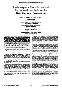
the ways in which results are presented to someone). When this was done, the system managed to link all the necessary concepts together by itself at the first try. Next the geometry of the conductor was modified and the system suggested a possible solution with the help of the available facts and heuristics [3]. Two intelligent tasks were performed here by the system. First it recognized various components in the figure and then it selected the concepts that are necessary to manipulate the situation encountered. Fig. 5.1 gives the flux pattern obtained by the finite element method. The object involved models of flux lines as a set of splines and Fig. 5.2 illustrates the result of the message DRAW-> sent to the FLUX object. Fig. 5.3 shows the lines of “no work,” also objects in our system, corresponding to the field configuration. Fig 5.4 shows the new of no work patterns under modifications to the size of the inner conductor as predicted by our program. The final form of the actual flux pattem can now be obtained with the help of this new set of no work lines.
5.1
5.2
W CONCLUSIONS The potential of using artificial intelligence techniques in electromagnetics will make computers come up with creative design ideas. This is recommended because of the wide range of applications in the domain of electromagnetics alone. No human designer can any longer play a “one-man-show.” Computers do not neglect or forget facts if they are presented to them properly and that is one criterion behind creativity. If this trend continues as expected, the term CAD (Computer Aided Design) will no longer be in use and instead the term H A D (Human Aided Design - as far as computers are concemed) will evolve.
5.3
REFERENCE
S. R. H. Hoole, Computer Aided Analysis and Design of Electromagnetic Devices, Elsevier, New York, 1989. S. R. H. Hoole and P. R. P. Hoole, “Building an expert system for interactive finite element design,” Proc. IEEE/CS Third Annual Workshop on Iinteractive Computing: CAE: Electrical Engineering, Pittsburgh, PA, pp. 90-93, Oct. 1984. D. Kurumbalapitiya and S. R. H. Hoole, “Heuristics for the solution of perturbed electromagneticfield problems,” Elsevier Studies in Applied Electromagnetics in MaterialsProceedings of the Fourth ISEM-Nagoya, 1992 (in press). C. L. Dym and R. E. Levitt, Knowledge Bused Systems in Engineering, McGraw-Hill, New York, 1991. J. Rumbaugh [et al.], Object-Oriented Modeling and Design, Prentice-Hall, Inc., Englewood Cliffs, New Jersey, 1991. E. Rich. and K. Knight, Artificial Intelligence, McGrawHill, Inc., New York, 1991. S. Keene, Object-Oriented Programming in Common Lisp, Addison-Wesley, Reading, Massachusetts, 1989. D. B. Lenat and E. A. Feigenbaum, “On the thresholds of knowledge.” Fundamentals of Artificial Intelligence, Edited by D. Kirsh, MIT/Elsevier, Cambridge, Massachusetts, 1992. ACKNOWLEDGEMENTS
This work is supported by the Harvey Mudd CollegeSouthern Califomia Edison Center for Excellence in Electrical Systems.
Fig. 5: Experimental Results. Dhammika Kurumbalapitiya was born in Sri Lanka on Aug. 26, 1964. He received the B.Sc. degree in Electrical Engineering with Honors from the University of Peradeniya in 1990. He is currently a doctoral candidate at the ENSEG, France, while working on his thesis at Harvey Mudd College.
S. Ratnajeevan H. Hoole (M’ 83, SM ‘89) was born in Tamil Ceylon on Sept. 15, 1952. He received the BSc. degree in electrical engineering (with honors) in 1975 from the University of Ceylon, the M.Sc. degree with the Mark of Distinction in electrical engineering from the University of London, in 1979. jointly offered through Imperial College and Queen Mary College, and the Ph.D. degree in electrical engineering from CarnegieMellon University, Pittsburgh, PA, in 1982. Dr. Hoole is the general chairman of the IEEE CEFC, and has published extensively on electromagnetic field computation. He is Professor of Engineering with continuous tenure at Harvey Mudd College. where he also teaches a course titled ‘The Political Economy OF South Asia,” and is the Director of the Sri Lanka Studies Institute, Claremont, CA.