An O(m2+mn2) Algorithm for the Bi-objective Location Problem on a Network with Mixed Metrics
Emanuel Melachrinoudis* Department of Mechanical and Industrial Engineering, Northeastern University, Boston, Massachusetts 02115, USA
[email protected] *Corresponding author Emre Yavuz Arcelik-LG, Kocaeli, Turkey
[email protected] Ruhollah Heydari Department of Mechanical and Industrial Engineering, Northeastern University, Boston, Massachusetts 02115, USA
[email protected]
Abstract In this paper, we formulate the Euclidean maximin with the network minisum biobjective location model for a semi-obnoxious facility on a transportation network that is embedded into the Euclidean plane. The Euclidean distance metric is used in modeling the undesirable characteristics of the facility, using the maximin objective, while the network shortest path distance metric is used for modeling the transportation cost to these facilities using the minisum objective. After identifying the problem properties, we develop an O(m2+mn2) algorithm for generating the efficient set and implement this algorithm in a realistic example involving the location of a semiobnoxious facility in the province of Bursa in Turkey. Keywords: semi-obnoxious facility; bi-objective location; maximin; minisum; network
2 Biographical notes: Emanuel Melachrinoudis is a Professor in the Department of Mechanical and Industrial Engineering at Northeastern University and also Associate Department Chair and Director of Industrial Engineering. His teaching is in the Operations Research area and his research is in mathematical modeling and optimization, especially with multiple criteria, with applications to facilities planning and location, supply chain management and logistics, vehicle routing and network reliability. He is a member of Editorial Board of the International Journal of Operational Research, International Journal of Mathematics in Operational Research, and Sensor Networks. Emre Yavuz is a logistics engineer at Arcelik-LG, Turkey. He received his B.S. in Industrial Engineering from Yildiz Technical University, Turkey, and his M.S. in Operations Research from Northeastern University. His research focus is on multiobjective facility location problems. Ruhollah Heydari is a Ph.D. candidate of Operations Research in the Department of Mechanical and Industrial Engineering at Northeastern University. He has been assigned as a graduate teacher assistant to various courses from Operations Research to Probability and Statistics to Engineering Decision Making. His research interest is in mathematical modeling, facilities location, supply chain management and network resiliency.
1
Introduction The public response to a new facility in their neighborhood depends on the nature of
their interaction with that facility. While community is usually open, and some time even eager, to some facilities such as libraries, chain-stores and bus and train stations,
3 people sometimes show resistance to some other facilities such as landfills and chemical plants because of their potential undesirable effects on public health/comfort. Such semi-obnoxious facilities, which provide positive effects globally, but negative ones locally are known as NIMBY (Not-In-My-Back-Yard) facilities and the act of the resistance or opposing to the new facility by the residents is called NIMBY phenomena (Plastria, et al. 2013; Bellettini and Kempf, 2013; Song et al., 2013). The residents believe that these facilities are needed in the society but they shouldn’t be located in their neighborhood. Locating a semi-obnoxious facility is becoming more challenging because of public awareness. In 2007, residents in the Xiamen city of China marched against a local Paraxylene (PX) plant, which eventually moved out of the city. Another protest in 2011 forced officials of Dalian to shut down
a controversial chemical plant.
(http://www.cnn.com/2011/WORLD/asiapcf/08/15/china.chemical.plant.shutdown/inde x.html). In 2012 a NIMBY protest forced the government officials in the city of Shifang in Sichuan–China to abandon a plan to build a $1.6 billion Molybdrenum plant (http://www.cnn.com/2012/07/06/world/asia/china-shifang-protest-florcruz).
In
their
“Toxic Wastes and Race at Twenty 1987—2007”, Bullard et al. (2007) point out that toxic waste sites are still sitting in the people of color communities and encourage officials to use “distance-based” methods in locating the waste facilities. These examples highlight the importance of using scientific methods and mathematical models to support the strategic decisions regarding semi-obnoxious facilities location. From a research point of view, semi-obnoxious facility location has been studied by means of a variety of operational research approaches from single objective optimization (Church and Garfinkel,1978; Welch and Salhi, 1997; Song et al., 2013) to game theory
4 (Karasakal and Nadirler, 2008; Bellettini and Kempf, 2013; Cheng et al., 2011 and 2013) to simulation (Heller et al., 1989), to metaheuristics (Yapicioglu et al., 2007; Medaglia et al., 2009 ) and to multiple objective facility location. In this study we focus on the latter which we describe in more detail below. A NIMBY or semi-obnoxious facility provides some service to population centers, thus it requires some travel to and from them. Therefore, in addition to minimizing the undesirable effects on populations, the location of such facilities should also consider minimizing transportation cost. This gave rise to the research on bi-objective models for locating semi-obnoxious facilities. These models are referred to as pull-push models since minimizing transportation costs implies to pull the facilities close to the demand centers and on the other hand minimizing undesirable effects of these facilities implies to push them away from the population centers. In other words, a location should be found that provides the best trade-off between the two objectives. Researchers have used different functions to represent the pull and push aspects of their modeling. The most popular pull objectives are (a) minimizing the total transportation cost, also known as minisum or median objective and (b) minimizing the distance between the new facility and its farthest facility, known as minimax or center objective. The most popular push objectives are (a) maximizing the total distance from existing facilities, known as maxisum or anti-median and (b) maximizing the distance between the new facility and its closest facility, known as maximin or anti-center objective. Depending on the nature of the problem they have also used different solution space, such as network and plane, and different distance metrics, such as rectilinear, Euclidean, and network distance, in their models.
5 In this paper we deal with the placement of a semi-obnoxious facility such as an airport, chemical plant, cement plant, incinerator or landfill. Common features of these facilities are (a) emissions of airborne pollution in the form of dust, gases, noise, odor and vibration that spread toward the population centers, and (b) required travel of materials, employees, energy or customers between these facilities and population centers on transportation networks. Therefore, we used Euclidean distances for the push objective and network distances for the pull objective. The push objective maximizes the minimum Euclidean distance from the population centers (maximin) while the pull objective minimizes the sum of weighted network distances representing the transportation cost (minisum). The solution space is the transportation network. In the reminder of this paper, we first review the literature of the semi-obnoxious facility location problems in Section 2 with a focus on bi-objective pull-push models. In Section 3, we propose our mathematical model on a linearly approximated transportation network that is embedded on the Euclidean plane. In Section 4, we explain in detail the solution methodology that generates the complete efficient set of the bi-objective problem. In Section 5, a numerical example involving the location of a semi-obnoxious facility in the Bursa Province of Turkey is presented. The paper ends with summary and conclusions in Section 6. 2
Literature Review Research in the area of bi-objective facility location for semi-obnoxious facilities
started in the mid 1980’s. Mehrez et al. (1985) formulated and solved the first biobjective problem for semi-obnoxious facility location. In their paper, the rectangular minimax and maximin objectives are combined and the new weighted objective is optimized on a square feasible region. They proved that the optimal solution lies at an
6 intersection point of the rectangular bisectors between any pair of demand points or boundary lines of the region. Drezner et al. (1986) demonstrated that if both minimax and maximin objectives are equiweight, then the solution of this problem lies either at closest-point or farthest-point Voronoi diagram. Needless to say that in this case the biobjective problem is practically reduced to a single objective problem which minimizes the range of the two objectives. Ohsawa (2000) considered the same problem, but he used Euclidean metrics for the distances and also instead of combining the objective functions, he developed a polynomial-time algorithm to compute the entire efficient set of the bi-objective model by taking advantage of the closest and farthest-point Voronoi diagrams. Ohsawa and Tamura (2003) showed that the efficient set of Mehrez et al. (1985) model is not restricted to single points only and may even include twodimensional areas. Ohsawa et al. (2006) reconsidered the Euclidean minimax-maximin problem where demand points and population centers do not exactly coincide and used higher-order Voronoi diagrams to solve the problem. Plastria, et al. (2013) considered a Euclidean distance minimax-maximin problem where contrary to the last three papers, protected convex polygonal regions represent population centers instead of simple points. Instead of finding the efficient set of the bi-objective model, they maximized a quadratic margin using the concept of Support Vector Machines (SVM). Finally Hamacher et al. (2002) developed an algorithm to solve this problem on a network taking advantage of the piecewise linearity of the objective functions. Using rectangular distances, Melachrinoudis (1999) developed a minisum-maximin model. This problem was solved by generating a series of O(n2 ) linear programs as in Drezner and Wesolowsky (1983), but instead of solving the LPs by simplex, Melachrinoudis constructed the entire nondominated and efficient sets by reducing each
7 LP to simple variable ranges using the Fourier-Motzkin elimination process. Karasakal and Nadirler (2008) proposed an Interactive Generalized Big Square Small Square (IGBSSS) method to solve this problem. After fathoming the inefficient parts of the feasible region, they involve the decision maker in an interactive search in the remaining regions in order to find the most preferred efficient solution. Melachrinoudis and Xanthopulos (2003) solved the Euclidean distance version of this model using the K-K-T optimality conditions and Voronoi diagrams. Hamacher et al. (2002) studied a location model with minisum and maxisum objectives on a network. Their method consists of direct mapping of the network into objective space and then calculating the lower envelope that is similar to Hershberger (1989). Skriver and Andersen (2003) provided an approximation algorithm called Edge Dividing (ED) method for this model where each edge is divided into two sub-edges and the bounds on the objective function values on each sub-edge are calculated. If the bounds of a sub-edge are dominated by a sample set of objective values, then the subedge is dominated. Brimberg and Juel (1998) used Euclidean distances in a bi-objective problem that combines the minisum objective and a second minisum objective which had the Euclidean distances raised to a negative power and developed a heuristic branch and bound algorithm, namely Big Square Small Square (BSSS), to solve this model. Skriver and Andersen (2003) studied this model but they used different norms for distance metrics of the objectives. For finding the efficient set, instead of combining the two objective functions, they provided an approximation algorithm for the bi-objective model based upon BSSS. Yapicioglou et al. (2007) developed a similar bi-objective model where the second minisum objective is modified further to model undesirable
8 effects as a function of distance. They used Particle Swarm Optimization (PSO) to approximate the efficient set. A vast literature review of PSO algorithms is presented in Rameshkumar et al. (2012). In addition to the above traditional pull-push models, researchers have suggested other objectives based on the nature of the problem they are studying. For instance, Plastria and Carrizosa (1999) solved a minimal covering problem by locating an open disk in a network/plane with respect to two objectives; first to maximize the radius of the disk of affected points and second to minimize the affected population. Rakas et al. (2004) took political perspectives into consideration and developed a model to optimally locate landfill sites, minimizing the total costs and political opposition. They solved their model using CPLEX after combining the normalized objective functions and creating a single objective function. Berman and Wang (2008) presented two network models with a given budget to expropriate the closest demand nodes. In the first model, they minimized the difference between the maximum and the minimum weighted distances. Their second model was the weighted maximin objective subject to a constrained maximum weighted distance. They proposed some polynomial time algorithms to solve these models. Tralhao et al. (2010) proposed a multi-objective MILP model to locate semi-obnoxious urban facilities considering four objectives: minimizing the total investment cost, the average distance from customers to facilities, the number of individuals too close to any facility, and the number of customers too far from the assigned facility. In order to ease the process of decision making, they provided a number of nondominated solutions using the weighting method, imposing a constraint on the maximum value of the cost objective and minimizing the distance to the ‘‘ideal solution”, which is a (not necessarily feasible) solution that optimizes all the objectives.
9 Coutinho-Rodrigues et al. (2012) considered an application of bi-objective semiobnoxious facility location in urban planning to minimize the total investment cost as a well as minimizing the dissatisfaction function in locating urban waste collection centers. The dissatisfaction function they used is a distance based function combining the attraction and repulsion characteristics of the waste containers. They developed a constraint method (imposing a constraint on the maximum value of the investment cost objective, and minimizing the dissatisfaction objective) in order to obtain the complete set of nondominated solutions of their MILP model. A comprehensive review of semiobnoxious facility location problems is presented in Melachrinoudis (2011). The majority of bi-objective models for locating a semi-obnoxious facility, consider a similar distance metric for push and pull objectives. However, this approach may not be appropriate in many cases where a combination of different distance metrics (mixed metrics) can help to construct more realistic models (Melachrinoudis, 1999). Ohsawa and Tamura (2003) dealt with a location model for the placement of a semi-obnoxious facility with mixed planar distances using elliptic distances for the maximin objective but rectangular distances for the minisum objective. This is more realistic than previous models as pollution does not travel in the same path that cars do. However, still both metrics are defined on the plane, the solution space is assumed to be continuous and travel is restricted along two rectangular directions. Placing facilities on or adjacent to the transportation network and using network distances to express transportation cost seems even more realistic. For the first time Heydari and Melachrinoudis (2012) combined network and planar distances in one model. They developed an algorithm to solve the case of a network minisum and elliptic maximin model on a network space. While the simulation results show their algorithm has a polynomial average complexity,
10 they didn’t provide worst case complexity. Their work also lacks a close form trade-off function. In this paper Euclidean metric (instead of elliptic) is assumed for the maximin model. This made it possible to demonstrate worst case complexity of the solution algorithm and to develop a close form trade-off function between the two objectives. 3 3.1
Mathematical Model Problem Definition Let 𝐺(𝑉, 𝐸) be an undirected, connected planar network with node set V (|V| = n)
and edge set E (|E| = m) representing the transportation network. The road segments (edges) have simple geometry; typically, they are simplified to straight or curved line segments. In this paper, however we linearly approximate all curved roads to straight line segments by means of introducing some artificial nodes to the network. The edge set 𝐸 = {𝑒1 , 𝑒2 , … 𝑒𝑚 } represents road segments between the nodes and 𝑒𝑘 = (𝑝, 𝑞) if 𝑝 and 𝑞 belong to 𝑉 and are adjacent. Each edge 𝑒𝑘 = (𝑝, 𝑞) ∈ 𝐸 has a positive length 𝑐𝑘 measured from node 𝑝 to node 𝑞 through the underlying edge. Let 𝐺 also denote the continuum of points 𝑋 on all edges of network 𝐺(𝑉, 𝐸), including all nodes. A point 𝑋 ∈ 𝑒𝑘 = (𝑝, 𝑞) can be denoted in two different ways. It can be addressed as a point on the network by a pair 𝑋 = (𝑒𝑘 , 𝑡) where t (0 ≤ 𝑡 ≤ 1) gives the relative position of X along the edge. It can also be defined by its Cartesian coordinates, i.e. 𝑋 = (𝑥, 𝑦) since it also belongs to the Euclidean plane. Let 𝑑𝐸 (𝑖, 𝑋) denote the Euclidean distance between a population center 𝑖 ∈ 𝑃 and an arbitrary point 𝑋 on an edge (𝑝, 𝑞) ∈ 𝐸and 𝑑𝑁 (𝑖, 𝑋) denote the shortest path network distance between them. For the sake of simplicity, let 𝑑𝑝𝑞 denote the shortest path network distance from node 𝑝 to node 𝑞.
11 Associated with each population center i, 𝑖 ∈ 𝑃, there exists a polygon Vi, called Voronoi
polygon,
with
the
following
property:
if
X Vi ,
then
d E (i, X ) d E ( j, X ), j P . The polygon Vi is the intersection of half-planes containing
i, the half-planes determined by the perpendicular bisectors of the line segments joining i and j, j ≠ i. The edges of the Voronoi polygons, some of which are unbounded halflines, are called Voronoi edges and their vertices are called Voronoi vertices. A Voronoi vertex is the common point of at least three Voronoi polygons, i.e., is equidistant from at least three points 𝑖 ∈ 𝑃. The circle drawn with center a Voronoi vertex and radius the distance to its equidistant points contains no 𝑖 ∈ 𝑃 points in its interior (empty circle). The Voronoi vertex associated with the largest empty circle is the optimal solution to Euclidean maximin problem in a planar feasible region (Shamos and Hoey, 1975). 3.2
Problem Formulation With the notation introduced in Section 3.1, 𝑃 ⊂ 𝑉 is the set of the population
centers, 𝑋 is the new facility location, and 𝑑𝐸 (𝑖, 𝑋) is the Euclidean distance between a population center at 𝑖 ∈ 𝑃 and the new facility at 𝑋 ∈ 𝐺. The 1-maximin objective seeks a location 𝑋 ∈ 𝐺 for an undesirable facility as far away as possible from the closest population center 𝑖 ∈ 𝑃.
max f ( X ) min d E (i, X ) iP
subject to
(2.1)
X G
∗ Let 𝑋𝑀,𝑘 denote the maximin point of edge 𝑒𝑘 ∈ 𝐸 and 𝑋𝑀 the point that solves
(2.1) on network 𝐺 (global maximin), associated with the optimal objective function ∗ value 𝑓(𝑋𝑀 ). While objective f(X) is neither concave nor convex on its entire domain, it
is a convex function on any line segment, entirely located in a Voronoi polygon Vi of a
12 population center i ∈ 𝑃. This is because f(X) reduces to the Euclidean distance between population center i and point X which is a convex function of X (Love and Morris, 1979).
Figure 1. Convexity of f (X ) function in a given Voronoi polygon As it is illustrated in Figure 1, f (X ) is a hyperbolic function. If the line extension of segment AB passes through the population center 𝑖 ∈ 𝑃 which is in the same Voronoi polygon, then f (X ) is a linear function over the line segment AB. This property provides a method for determining the maximin point of an edge 𝑒𝑘 = (𝑝, 𝑞): Over an edge 𝑒𝑘 = (𝑝, 𝑞) ∈ 𝐸, let {𝑒𝑘_0 , … , 𝑒𝑘_𝑙 , … , 𝑒𝑘_𝑙𝑘 } ⊂ 𝑒𝑘 be the set of intersection points with Voronoi edges, and incident nodes 𝑝 and 𝑞, where 𝑒𝑘_0 and 𝑒𝑘_𝑙𝑘 represent 𝑝 and 𝑞, respectively. Evaluate f (X ) at every point 𝑒𝑘_𝑙 ∈ {𝑒𝑘_0 , 𝑒𝑘_1 , … , 𝑒𝑘_𝑙𝑘 } of edge 𝑒𝑘 and select the point with the maximum value. Note that for 𝑒𝑘_𝑙 ∈ 𝑉𝑗 ,
min d E (i, ek _ l ) d E ( j, ek _ l ) . iP
13 Transportation costs increase with the distance between the facility and the users. In order to minimize the total transportation cost, the new facility should be located as close as possible to the existing users. Let 𝑤𝑖 denote the positive weight associated with the population center 𝑖 ∈ 𝑃 representing its demand. The minisum (median) problem seeks a point 𝑋 on the network 𝐺 that minimizes the sum of its weighted shortest path network distances from all population centers 𝑖 ∈ 𝑃.
min g ( X ) wi d N (i, X ) iP subject to X G
(2.2)
The weighted-sum objective g(X) is a continuous, piecewise linear, concave function on the edges, with breakpoints only in the edge bottleneck points. An interior point X on an edge (𝑝, 𝑞) is called a bottleneck point of node 𝑖 ∈ 𝑉 if 𝑑𝑖𝑝 + ck ( p, X ) = 𝑑𝑖𝑞 + ck (q, X ) , where ck ( p, X ) is the length of the arc from point X on the edge (𝑝, 𝑞) to endpoint p (Church and Garfinkel, 1978). According to Hakimi’s vertex optimality property, edge minisum location occurs on one of the two incident nodes or an infinite number of alternative locations exists on the whole edge from 𝑝 to 𝑞 (Hakimi, 1964). Similarly based on piecewise linearity and convexity properties of this function, there exists either a unique edge maxisum location, denoted by 𝑋𝑆,𝑘 , (Figure 2(i)) or an infinite number of alternative locations defined on an edge segment [ X S ,k , X S' ,k ] (see Figure 2(ii)).
14
Figure 2. Concavity of g (X ) function
Finally, the Euclidean maximin with the network minisum bi-objective location model for a semi-obnoxious facility seeks to find the set of efficient points, S G , or
max f ( X ) min d E (i, X ) iP
min g ( X ) wi d N (i, X ) iP subject to X G
(2.3)
where a point 𝑋 ′ ∈ 𝐺 is efficient if and only if there does not exist another point 𝑋 ∈ 𝐺 such that 𝑓(𝑋) ≥ 𝑓(𝑋 ′ ), and g(𝑋) ≤ g(𝑋 ′ ) and at least one is satisfied as strict inequality. Otherwise, 𝑋 ′ is inefficient. The image of efficient set in objective space is called nondominated set. 4
Solution Methodology In order to find the nondominated set of (2.3), we need both to identify all the
maximin and minisum locations, and to investigate other characteristic points, namely,
15 edge bottleneck points and intersection points of the network edges with the Voronoi diagram. 4.1
Fathoming Rules In this section we develop powerful fathoming rules to eliminate the inefficient
subsets of the network. These rules are used in whole-edge and edge segment elimination procedures later. Lemma 1 Consider any two edges, ea ( p, q) and eb ( p' , q' ) , 1 a, b m . If
min g ( p), g (q) g ( X M ,b ) , and f ( X M , a ) f ( X M ,b ) , then ea contains no efficient points. Proof The objective vector at X M ,b dominates the objective vector at any X ea and as shown in Figure 3, g ( X M ,b ) is always less than or equal to g (X ) , X ea because of the concavity property of g (X ) function. Therefore, ea contains no efficient points.
Figure 3. The edge ea contains no efficient points Lemma 1 is instrumental in fathoming dominated edges as is shown later in the whole-edge elimination procedure. For example, we can let 𝑒𝑏 be an edge with large
■
16
f ( X M ,b ) and small g ( X M ,b ) values, and compare it with all other 𝑒𝑘 = (𝑝, 𝑞) ∈ 𝐸, 𝑘 = 1, … , 𝑚, 𝑘 ≠ 𝑏. After fathoming inefficient edges, we may fathom inefficient parts of the remaining edges using the following lemmas. Lemma 2 Consider an edge ek ( p, q) E . If g ( X M ,k ) maxg ( p), g (q), then the segment between X M ,k and i * arg max g ( X ) contains no efficient points. X p , q
Proof The objective vector at X M ,k dominates the objective vector of any point
X ( X M ,k , i * ] .
■
Figure 4. The edge segments ( x M ,k , i * ] are inefficient Figure 4(i) and (ii) illustrate Lemma 2. If there is an edge ek ( p, q) E , such that g ( X M ,k ) maxg ( p), g (q), then except for X M ,k , the segment between X M ,k and i * arg max g ( X ) is dominated by the point X M ,k and may be therefore eliminated X p , q
from further consideration. Lemma 2 is used in the inefficient edge segment elimination procedure later (Procedure 2).
17 Lemma 3 The segment between X M ,k and X S ,k on each edge ek ( p, q) E contains no efficient points.
Figure 5. The edge segments ( X M ,k , X S ,k ] are inefficient Proof The objective vector at X M ,k dominates the objective vector of any point X ( X M ,k , X S ,k ] .
■
Figure 5 (i) and (ii) illustrate Lemma 3. If there is an edge ek , such that the maxisum occurs in all points of an edge segment [ X S ,k , X S' ,k ] ek , and X M ,k ( X S ,k , X S' ,k ) , then except for X M ,k , the edge segment [ X S ,k , X S' ,k ] is inefficient (see Figure 5(iii)). Similarly, If there is an edge ek , such that g ( X M' ,k ) g ( X M ,k ) , and X S ,k
18
( X M ,k , X M' ,k ) , except for X M ,k and X M' ,k , the edge segment ( X M ,k , X M' ,k ) is inefficient (see Figure 5(iv)). Similarly to Lemma 2, Lemma 3 is also used in the inefficient edge segment elimination procedure. 4.2
Trade-off Curve Formulation Consider a road line segment that is within a Voronoi polygon Vi generated by
population center i located at point I ( xi , yi ) . Let A ( xa , ya ) and B ( xb , yb ) be two consecutive bottleneck points of that road segment as shown in Figure 6(i), or, otherwise, be two points of a road segment between two consecutive bottleneck points. Then, g (X ) is linear for X AB , as illustrated in Figure 6(ii).
Figure 6. A road segment AB within Vi and objective function g(X), X AB .
Lemma 4 Let point I represent a population center and points A and B be two consecutive bottleneck points on a road line segment that is within the Voronoi polygon generated by I. The trade-off curve on road line segment AB, f (g ) is given by:
f ( g ) ( B A) g ( A I ) g B ( B I ) g A
gB g A
(3.1)
19 where g A , g B and g are the g(X) objective values at points A, B and X AB , respectively. Proof Let g ( X ) g . For X AB , X ( x, y) , we have (Figure 6):
XA x xa y ya g gA xb xa yb ya B A gB g A
(3.2)
By combining the first two terms of (3.2) with the last term and solving for x and y, respectively, we obtain (3.3) and (3.4) below.
x
( xb xa )( g g A ) xa gB g A
(3.3)
y
( yb ya )( g g A ) ya gB g A
(3.4)
Since AB is within the Voronoi polygon generated by population center i and X AB , f ( X ) min d E (i, X ) X I ( x xi ) 2 ( y yi ) 2
(3.5)
iP
Substituting x and y from (3.3) and (3.4) in (3.5), we obtain: 2
2
( x x )( g g A ) ( y ya )( g g A ) f (g) b a xa xi b y a yi , gB g A gB g A
which when further simplified and brought into vector form becomes (3.1).
(3.6)
■
After fathoming inefficient subsets, we use this formulation to construct the trade-off curve of the maximin and minisum functions in the objective space. 4.3
Procedure 1: Fathoming Inefficient Edges Over an edge 𝑒𝑘 = (𝑝, 𝑞) ∈ 𝐸, let {𝑒𝑘_0 , … , 𝑒𝑘_𝑙 , … , 𝑒𝑘_𝑙𝑘 } ⊂ 𝑒𝑘 be the set of
bottleneck points, intersection points with Voronoi edges, and incident nodes 𝑝 and 𝑞,
20 where, 𝑒𝑘_0 and 𝑒𝑘_𝑙𝑘 represent 𝑝 and 𝑞, respectively and 𝑝 < 𝑞. Let call this set as the set of breakpoints. Let also (𝑘_𝑠, 𝑘_𝑡) denote an edge segment or edge segments between the 𝑠 𝑡ℎ and 𝑡𝑡ℎ breakpoints of 𝑒𝑘 . Also let us define a two-row array Uk . First row of Uk consists of the breakpoints 𝑒𝑘_𝑙 and second row shows if this point is a node (number 1), an intersection point of the network with the Voronoi diagram (number 2), 𝑒 (1,1) (2,3) (3,5) (5,9) or a bottleneck point (number 3). For example Uk = [ 𝑘_𝑙 ] = [ ] # 1 3 2 1 shows that points ek_1 = (2,3) and ek_2 = (3,5) are respectively a bottleneck point and an intersection point of Voronoi diagram with an edge of the network with the end points p = ek_0 = (1,1) and q = ek_3 = (5,9). Edge segment between points (2,3) and (5,9) on this edge may be referred as (k_1,k_3). Let A be the set of edges that contain no efficient points (set of eliminated edges) and B be the set of edges that may contain efficient points. Inefficient edge elimination procedure is presented below.
INPUT: G= (V, E), |V| = n, |E| = m; 𝑈𝑘 , 𝑘 = 1, … , 𝑚; A= ; B= STEP 1: Determine X M ,k and evaluate f ( X M ,k ) for k 1,..., m. Evaluate g (i) , i V . Evaluate g ( X M ,k ) for k 1,..., m. Rank the edges in decreasing order of objective function f ( X M ,K ) values and save them in array E’. Rank the edges in decreasing order of min g ( p), g (q) values and save p ,q ek ( p ,q )
E”.
them in array Make a copy of edge set E as E "' E. "' STEP 2: For the edge eb E that has the best maximin value, i.e. the first element of array E’, B B eb ( eb may contain efficient points.)
E "' E "' eb E ' E ' eb , E " E " eb STEP 3: While E "' ,
21 "' For the edge ea E that has the maximum value of
min
g ( p), g (q), i.e.
p ,q ek ( p ,q )
the first element of array E”, If min g ( p), g (q) g ( X M ,b ) p ,q ea ( p ,q )
A A ea
( ea contains no efficient points.)
E "' E "' ea E ' E ' ea , E " E " ea Go to STEP 3. Else Go to STEP 2. OUTPUT: B; g (i) , i V ; X M ,k , g ( X M ,k ) , and f ( X M ,k ) , k = 1,…,m
In the first step we evaluate f (X ) values of all intersection points of the edge
ek with the Voronoi diagram as well as its endpoints to determine the edge maximin point X M ,k for 𝑘 = 1, … , 𝑚. Then, we evaluate g (i) for all network nodes and use these values to calculate the transportation cost at edge maximin points. In order to lower the complexity of Step 2 and 3, we define two new arrays E’ and E” with same elements as E but in different orders. Edges in E’ (E”) are sorted on decreasing order of their corresponding maximin value (minimum transportation cost of end points). Also as we need to keep the original network G, we make a copy of edge set E and start the fathoming process on this set E "' . Next, we construct Step 2 and Step 3 by using Lemma 1. In each iteration of Step 2, we consider unfathomed edge eb which has the best maximin value, i.e. the first element of array E’, then remove eb from the set E "' and add it into the set B. In Step 3, we compare the sum function value of the point "' X M ,b and the sum function value of the edge ea E , which is the first element of array
E” and has the worst edge minisum value. If the edge minisum value of ea is greater than or equal to the sum value of X M ,b , ea contains no efficient points and therefore we
22 remove it from the set E "' and add it into the set A. We repeat this step as long as the condition is satisfied; otherwise we go back to Step 2. The procedure stops when E "' becomes an empty set. The worst case complexity analysis of Procedure 1 is as follows. For each edge, objective function f needs to be evaluated on its two end points and on O(|P|) number of its intersection points with the Voronoi diagram. X M ,k for one edge can be determined by finding the maximum value among those O(|P|) numbers which requires O(log |P|) effort. g (i) for a node i can be computed by summing up its distances from |P| demand points which requires O(|P|) effort. g ( X M ,k ) for an edge k can be computed in O(|P|) time with similar analysis. Hence determining X M ,k for all edges and calculating objective values of these points requires a total O(m|P| + n|P|) effort. Furthermore, sorting edges with respect to the value of an objective function requires O(m log m) operations. Finally, pairwise comparison of the network edges in Step 2 and 3, is performed in O(m2) time. The worst case, O(m2), happens only if Lemma 1 fails to dominate any edges. As a result, Procedure 1 runs in O(n|P| + m|P| + m2) time.
4.4
Procedure 2: Fathoming Inefficient Edge Segments In the procedure presented below, we eliminate the inefficient subsets of set B
containing the remaining edges after implementing the whole-edge elimination procedure. INPUT: G= (V, E); g (i) , i V ; X M ,k , g ( X M ,k ) , and f ( X M ,k ) , 𝑘|𝑒𝑘 ∈ 𝐵; 𝑈𝑘 , 𝑘|𝑒𝑘 ∈ 𝐵 STEP 1: Determine X S ,k for ek B STEP 2: For each ek ( p, q) B do
If g ( X M ,k ) maxg ( p), g (q)
23 let i * arg max g (i) i p , q
bk ek ( X M ,k , i * ] else bk ek ( X M ,k , X S ,k ]
endif enddo OUTPUT: B; X S ,k , bk ek ( p, q), ek B In Step 1, we determine the edge maxisum points for ek B using the method of Church and Garfinkel (1978). As the number of bottleneck points on an edge of the network is bounded by n, calculating g for all breakpoints on this edge needs O(n|P|) time and finding the maximum among them, i.e. maxisum on the edge, needs O(log n) operations. Hence step 1 on a network with m edges can be performed in O(mn|P|) time. In Step 2, we fathom inefficient edge segments using Lemma 2 and 3 which requires O(1) time. So the overall complexity of Procedure 2 which belongs to Step 1 is O(mn|P|).
4.5
Algorithm for Finding the Efficient Set We develop the following Algorithm that finds efficient location for a semi-
obnoxious facility based on fathoming inefficient subsets of 𝐺, mapping unfathomed subset into the objective space, constructing the nondominated set and returning the inverse image of this nondominated set as the efficient set. Input: G = (V, E); wi , i P Phase 1: Construct the bottleneck point set, then construct the Voronoi diagram and find the set of its intersection points with the network. Merge the two sets and sort the elements to build set {ek _ 0 ,..., ek _ lk }, ek E and array Uk, k = 1,…,m as was explained in Section 4.3. Phase 2: Using Procedure 1, eliminate inefficient edge set A. Let B be the set of remaining edges. Phase 3: For all edges in B, using Procedure 2, eliminate inefficient edge segments. Let bk ek , ek B be the unfathomed part of the k th edge.
24 Phase 4: In objective space, draw ( f ( g ), g ) for all bk B and determine the upper and leftward envelope L of ( f ( g ), g ). Phase 5: In decision space, find the inverse image S of set L. Output: Efficient set S G . In the Algorithm, firstly, we eliminate inefficient edges and edge segments using the procedures introduced in Section 4.3 and 4.4. Next, we map the remaining edges and edge segments into the objective space via the formula that was presented in Lemma 4. Let us consider the objective space where g(𝑋) is measured along horizontal scale and 𝑓(𝑋) along the vertical. The leftward and upper directions are better in terms of pull and push objectives, respectively. Therefore, the nondominated set corresponds to the trade-off curve that coincides with the upper and leftward envelope of collection of curves that are associated with the unfathomed subset. Finally, we obtain the efficient sets in decision space by inverse mapping of the set L. 4.6
Complexity of the Algorithm Dijkstra’s algorithm with Fibonachi heaps can compute all-pair shortest paths in
O(nm + n2 log n) time (Fredman and Tarjan, 1987). Knowing the shortest paths, the set of bottleneck points can be computed in O(nm) time. The Voronoi diagram can be constructed in O(|P| log |P|) time (Scheike, 1994). Since there exist O(|P|) Voronoi edges, there would be O(|P|) intersection points between the Voronoi diagram and every network edge. Noting that |P| < n, the maximum number of bottleneck points and Voronoi intersections on an edge is O(n), requiring O(n log n) effort to order them on the edge. Considering that there are m edges in G, the complexity of Phase 1 of the algorithm is O(nm log n + n2 log n). Phase 2 and Phase 3 can be implemented in O(m2 + mn|P|) time as derived in Section 4.3 and 4.4. Since the number of bottleneck points and Voronoi intersections on each edge is in O(n), the network consists of O(mn) edges and edge segments. As we proved at Section
25 4.2, f
2
is quadratic with respect to g, so the loci corresponding to any two edge
segments of the network intersect each other at most twice. Hence, Phase 4 requires O(nm log nm) time, as shown in Boissonnat and Yvinec (1998). Since the envelope L of (f(g),g) contains O(mn) curves, Phase 5 can be implemented in O(mn) operations (Ohsawa and Tamura, 2003). Therefore, the required effort to find the efficient set of the problem is O(nm log n + n2 log n + m2 + mn|P|) and since |P| < n, the worst case complexity of the Algorithm is O(m2 + mn2). 5
Numerical Example Bursa is a province in northwestern Turkey with a total population of 2,550,645
According to Turkish Statistical Institute, 2009 (http://tuikapp.tuik.gov.tr/adnksdagitapp /adnks.zul). It is the fourth biggest city of Turkey as well as one of the most industrialized and culturally charged metropolitan centers in the country. The fifteen main population centers of the Bursa Province with the corresponding populations are Bursa (1,651,819), Gursu (55,155), Kestel (47,709), Inegol (215,375), Yenisehir (51,420), Iznik (44,756), Orhangazi (75,127), Gemlik (99,234), Mudanya (69,954), Karacabey (78,824), Kemalpasa (101,800), Harmancik (7,994), Buyukorhan (13,244), Orhaneli (23,992) and Keles (15,242). In this study, we normalize the number of populations according to the 𝐿1 norm and assign them as population center weights in the minisum objective. The geographical features of the region such as lakes, mountains and rivers have direct impact on the population distribution, economic resources and most importantly the transportation network of this region. The topography of a region has also a great effect on the form of the transportation network. If we consider smooth regions, we can observe that the network distances between any two points are really close to the
26 Euclidean distances, but, for mountainous regions, network distances are much greater than Euclidean distances because of the curvy road structure. For instance, Keles (node 15) and Inegol (node 4) are close to each other according to the Euclidean distance, but the network distances which are used for transportation are twice more than the Euclidean distance because of the huge mountain between those population centers. In the boundaries of the Bursa Province, there are two lakes, many river networks and numerous mountains. Therefore, the form of the transportation network of Bursa is complicated due to the topography of the province. The decision space of our numerical example presented in Figure 8 is a linearly approximated transportation network with a total length of 887 km. There 15 population centers, 16 road junctions, 10 boundary intersections, 49 edges and 159 line segments in this network. In order to find the efficient set of the problem, the algorithm was implemented in MATLAB. In the first phase of the algorithm, the Voronoi diagram was created and its intersection points with the network were identified. Edge bottleneck points were then found. In the following subsections, we apply the algorithm step by step to find the efficient set. 5.1
Inefficient Edge Elimination Here, we apply the Procedure 1 to fathom inefficient edges. We evaluate g(𝑖)
values for 𝑖 ∈ 𝑉, and determine the population center Bursa (𝑖 = 1) as the median node with g(1) =17.57. Also, we evaluate 𝑓(𝑋) at all nodes and intersection points of the network edges with the Voronoi edges, i.e. {𝑒𝑘_0 , 𝑒𝑘_1 , … , 𝑒𝑘_𝑙𝑘 } for each edge k, and then by comparing them, we determine edge maximin point(s), 𝑋𝑀,𝑘 , for each edge 𝑒𝑘 . The intersection of the edge 𝑒8 = (11,20) with the Voronoi edge between Bursa and Kemalpasa is determined as the global maximin point 𝑒8_6 with 𝑓(𝑒8_6 ) =45.69. Point
27 𝑒8_6 has coordinates (100,126.3) and it is at a distance 37 km from node 11 on edge 𝑒8 = (11,20). Then, we implement the second and third steps of Procedure 1 to eliminate inefficient edges.
28
Table 1. Edge elimination procedure k
(p,q)
𝑓(𝑋𝑀,𝑘 )
1 2 3 4 5 6 7 8 9 10 11 12 13 14 15 16 17 18 19 20 21 22 23 24 25 26 27 28 29 30 31 32 33 34 35 36 36 38 39 40 41 42 43 44 45 46 47 48 49
(10,32) (10,16) (16,33) (16,17) (11,17) (11,34) (17,18) (11,20) (9,18) (18,19) (19,22) (19,20) (9,22) (21,22) (20,21) (1,21) (22,25) (21,23) (14,23) (14,24) (13,24) (12,24) (12,35) (12,36) (15,23) (15,37) (1,25) (1,2) (2,3) (3,30) (30,31) (4,31) (4,38) (4,5) (28,31) (5,28) (5,29) (6,29) (6,40) (6,7) (7,26) (8,26) (8,25) (25,30) (26,27) (27,28) (27,29) (5,39) (7,41)
25.72 3.05 32.87 12.07 19.16 25.27 34.73 45.69 36.90 39.50 21.78 21.78 17.27 19.78 16.78 12.17 20.05 19.85 29.63 15.37 17.10 22.00 15.93 14.19 26.51 25.10 20.05 8.85 2.60 11.00 17.52 21.05 43.22 18.05 26.75 18.05 15.65 7.71 18.53 28.40 13.61 11.02 21.33 20.05 19.75 32.65 30.20 25.07 8.60
g(𝑋𝑀,𝑘 )
49.64 62.63 55.18 46.60 46.60 28.48 26.13 23.55 24.56 36.89 47.50
54.67 24.56 21.83
43.91
25.72
56.02
min{g(p),g(q)} Iteration 97.85 95.97 95.97 90.34 81.40 81.40 56.00 26.13 43.31 46.60 29.90 26.13 29.90 23.55 23.55 17.57 24.56 23.55 36.89 72.58 85.36 85.36 109.21 109.21 36.89 82.34 17.57 17.57 24.99 27.15 32.14 35.10 50.89 50.89 35.10 48.05 58.33 72.99 77.52 54.18 44.12 38.23 24.56 24.56 44.12 48.05 55.58 58.33 54.18
1-1 1-2 1-3 1-4 1-5 1-6 1-7 1 3 2 8 9 10-1 14 15 16 11 13 5 1-8 1-9 1-10 1-11 1-12 7 1-13 12 17 11-1 10-2 10-3 10-4 1-14 1-15 6 5-1 1-16 1-17 1-18 1-19 6-1 10-5 10 11-2 6-2 4 1-20 1-21 1-22
29 Table 1 shows the iterations of the second and third steps of Procedure 1. In the table, grey highlighted edges are the fathomed inefficient edges. For example, in Iteration 1 which includes Step 2 of Procedure 1, the best maximin value occurred at the point 𝑒8_6 obtained from edge 𝑒8 = (11,20), and therefore edge 𝑒8 was removed from edge set E and was added into the unfathomed edge set B. By comparing g(𝑋𝑀,8 ) = 49.64 with the min{g(p),g(q)} values of other edges in E, in the third step of Procedure 1, we applied 22 sub-iterations (1-1, 1-2,…,1-22) and fathomed
22 edges whose
min{g(p),g(q)} value is greater than or equal to g(𝑋𝑀,8 ). We removed these edges from the input edge set E and added into the fathomed edge set A. After that, we repeated Step 2 and 3, and identified unfathomed edges and inefficient edges which are presented by main iterations (1,2,…,17) and sub-iterations (1-1,1-2,…, 11-2), respectively, until set E became an empty set. 32 inefficient edges out of 49 (65%) were eliminated. In terms of network distances, 59.2% of the decision space was fathomed. The 17 remaining unfathomed edges were evaluated in Phase 3. 5.2
Inefficient Edge Segment Elimination In this phase we apply Procedure 2 on the remaining edges of the network, i.e.
set B, to eliminate inefficient edge segments. Table 2. Edge segment elimination procedure
30 k
(𝑝, 𝑞) ∈B
8 9 10 11 12 14 15 16 17 18 19 25 27 28 35 43 46
(11,20) (9,18) (18,19) (19,22) (19,20) (21,22) (20,21) (1,21) (22,25) (21,23) (14,23) (15,23) (1,25) (1,2) (28,31) (8,25) (27,28)
g(𝑋𝑀,𝑘 ) 𝑚𝑎𝑥{g(𝑝),g(𝑞)} 49.64 62.63 55.18 46.60 46.60 28.48 26.13 23.55 24.56 36.89 47.50 54.67 24.56 21.83 43.91 25.72 56.02
g(𝑋𝑀,𝑘 ) i* ≤ 𝑚𝑎𝑥{g(𝑝),g(𝑞)}
81.40 56.00 56.00 46.60 46.60 29.90 26.13 23.55 29.90 36.89 72.58 82.34 24.56 24.99 48.05 38.23 55.58
Yes No Yes No No Yes No No Yes No Yes Yes No Yes Yes Yes No
11 18
22
22 14 15 2 28 8
𝑏𝑘
𝑋𝑆,𝑘 ∈ 𝑏𝑘
𝑏𝑘
e8-(8_6,8_0] e9 e10-(10_1,10_0] e11 e12 e14-(14_1,14_0] e15 e16 e17-(17_2,17_0] e18 e19-(19_4,19_9] e25-(25_2,25_7] e27 e28-(28_1,28_3] e35-(35_2,35_3] e43-(43_1,43_4] e46
No Yes No Yes No No No No No No No No No No No No Yes
e8-(8_6,8_0] e9-(9_2,9_4_1] e10-(10_1,10_0] e11-(11_0,11_2] e12 e14-(14_1,14_0] e15 e16 e17-(17_2,17_0] e18 e19-(19_4,19_9] e25-(25_2,25_7] e27 e28-(28_1,28_3] e35-(35_2,35_3] e43-(43_1,43_4] e46-(46_5,46_3]
The inefficient edge segment fathoming process is presented Table 2. In this phase, inefficient parts of 12 edges out of 17 edges were eliminated, corresponding to 16% of the decision space (network length). Only 5 edges remained unchanged. For example, in Table 2, for edge 𝑒8 = (11,20), we eliminated the edge segment (8_0,8_6] (between Kemalpasa (11) and the edge maximin point 𝑋𝑀,8 = 𝑒8_6 ) using Lemma 2. For edge 𝑒11 = (19,22), we fathomed edge segment (11_0,11_2] (between the node 19 and a bottleneck point on the line segment (11_0,11_3) which is the edge maxisum point 𝑋𝑆,11 . The remaining edges and edge segments, 𝑏𝑘 ⊂ 𝑒𝑘 , 𝑒𝑘 ∈ 𝐵 are mapped into the objective space in the next phase. Altogether the fathoming procedures eliminated a total of 667 km of inefficient edge and edge segments out of 887 km of the whole transportation network. This corresponds to 75.2% of the decision space. 5.3
Mapping Remaining Edges into Objective Space The formula presented in Lemma 4 is used to determine the trade-off curve of the
unfathomed edges and edge segments.
31
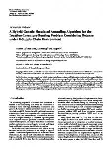
Figure 7. Trade-off curve of unfathomed edge set B Figure 7 shows the image of the unfathomed set in objective space, where g(𝑋) is measured along the horizontal axis and 𝑓(g) along the vertical axis. The upper and leftward directions are better in terms of the push and pull objectives, respectively. Therefore, a 2-dimensional search is implemented to construct the nondominated set which is the upper and leftward envelope of the loci. Finally, nondominated set L in the objective space is found as [ z 0 , z1 ] [ z1 , z 2 ] ( z 3 , z 4 ] [ z 5 , z 6 ] [ z 6 , z 7 ] (see Figure 7). 5.4
Mapping the Nondominated Set into Decision Space In the last step, we find the inverse image of the nondominated set L to obtain
the efficient set 𝑆 ⊂ 𝐺. As presented in Figure 8, the efficient set is [ x 0 , x1 ]
[ x1 , x 2 ] ( x 3 , x 4 ] [ x 5 , x 6 ] [ x 6 , x 7 ] . S consists of edge 𝑒27 = (1,25) and
32 three edge segments on edges 𝑒8 = (11,20), 𝑒12 = (19,20) and 𝑒43 = (8,25) whose total length is 3.7% of the length of the whole decision space.
Figure 8. Linearly approximated transportation network of the Bursa and the efficient set
6
Summary and Conclusions In this paper, we developed the Euclidean maximin with the weighted network
minisum bi-objective location model for locating a semi-obnoxious facility on a transportation network with mixed distance metrics. In many cases, it is more realistic to use a combination of different distance metrics and a solution space. Therefore, we used a mixed distance metric model in which linearly approximated road network is embedded on the plane, so that each point on the network corresponds to a point in the plane.
33 Instead of using a traditional solution approach, we investigated the properties of the bi-objective problem in both decision and objective space. In order to find the efficient set of the problem, we developed two powerful fathoming procedures to eliminate inefficient edges and edge segments. In addition, we developed a close form of the trade-off between the two objectives and demonstrated the polynomial O(m2 + mn2) worst case complexity of the algorithm.
The algorithm was tested in a realistic numerical example involving the placement of a semi-obnoxious facility in the Bursa Province of Turkey. The fathoming procedures enabled the elimination of dominated decision space equal to 75.2% of the total network decision space. The remaining network was mapped into the objective space. After determining the nondominated set and finding its inverse image we obtained the efficient set which is 3.7% of the entire decision space. The decision maker may select a point from the efficient set for the facility location, based on the trade-off between two objectives, his or her preference for the objectives and/or additional considerations.
34 References Bellettini G. and Kempf H. (2013) ‘Why not in your backyard? On the location and size of a public facility’, Regional Science and Urban Economics, Vol. 43, pp. 22–30. Berman O. and Wang Q. (2008) ‘Locating a semi-obnoxious facility with expropriation’, Computers and Operations Research, Vol. 35(2), pp. 392–403. Boissonnat, J.T. and Yvinec, M. (1998) Algorithmic Geometry, Cambridge University Press, Cambridge. Brimberg J. and Juel H. (1998) ‘A bicriteria model for locating a semi-desirable facility in the plane’, European Journal of Operational Research, Vol. 106, pp.144-151. Bullard R.D., Mohai P., Saha R. and Wright B. (2007) ‘Toxic Wastes and Race at Twenty, 1987—2007’, A report prepared for the United Church of Christ Justice and Witness Ministries, http://www.ucc.org/justice/pdfs/toxic20.pdf. Cheng Y., Han Q., Yu W. and Zhang G. (2013) ‘Obnoxious facility game with a bounded service range’, Theory and Applications of Models of Computation, Lecture Notes in Computer Science, Vol. 7876, pp. 272-281. Cheng Y., Yu W. and Zhang G. (2011) ‘Strategy-proof approximation mechanisms for an obnoxious facility game on networks’, Theoretical Computer Science, http://dx.doi.org/10.1016/j.tcs.2011.11.041. Church R.L. and Garfinkel R.S. (1978) ‘Locating an obnoxious facility on a network’, Transportation Science, Vol. 2, pp.107-118. Coutinho-Rodrigues J., Tralhao L. and Alcada-Almeida L. (2012) ‘A bi-objective modeling approach applied to an urban semi-desirable facility location problem’, European Journal of Operational Research, Vol. 223, pp. 203–213. Drezner Z., Thisse J.-F. and Wesolowsky G.O. (1986) ‘THE minimax-min location problem’, Journal of Regional Science, Vol. 26(1), pp. 87–101. Drezner Z. and Wesolowsky G.O. (1983) ‘Location of an obnoxious facility with rectangular distances’, Journal of Regional Science, Vol. 20, pp.241-248. Fredman M. L. and Tarjan R. E. (1987) ‘Fibonacci heaps and their uses in improved network optimization algorithms’, Journal of the Association for Computing Machinery, Vol. 34 No 3, pp.596–615. Hakimi, S.L. (1964) ‘Optimum locations of switching centres and the absolute centres and medians of a graph’, Operations Research, Vol. 12, pp.450-459.
35 Hamacher H.W., Labbe M., Nickel S. and Skriver A.J.V. (2002) ‘Multicriteria semi-obnoxious network location problems (MSNLP) with sum and center objectives’, Annals of Operational Research, Vol. 110, pp.33-53. Heller M., Cohon J.L. and ReVelle C.S. (1989). ‘The use of simulation in validating multi-objective EMS location model’, Annals of Operations Research, Vol. 18, pp. 303–322. Hershberger J. (1989) ‘Finding the upper envelope of n line segments in O(n log n) time’, Information Processing Letters, Vol. 33, pp.169–174. Heydari R. and Melachrinoudis E. (2012) ‘Location of a semi-obnoxious facility with elliptic maximin and network minisum objectives’, European journal of operational research, Vol. 223, pp.452-460. Karasakal E. and Nadirler D. (2008) ‘An interactive solution approach for a biobjective semi-desirable location problem’, Journal of Global Optimization, Vol. 42(2), pp. 177-199. Love R. and Morris J. (1979) ‘Mathematical models of road travel distances’, Management Science, Vol. 25, pp. 130–139. Medaglia A.L., Villegas J.G. and Rodriguez-Coca D.M. (2009) ‘Hybrid biobjective evolutionary algorithms for the design of a hospital waste management network’, Journal of Heuristics, Vol. 15, pp. 153–176. Mehrez A., Sinuany-Stern Z. and Stulman A. (1985) ‘A single facility location problem with a weighted maximin-minimax rectilinear distance’, Computers and Operations Research, Vol. 12, pp.51-60. Melachrinoudis E. (1999) ‘Bicriteria location of a semi-obnoxious facility’, Computers and Industrial Engineering, Vol. 37, pp.581-593. Melachrinoudis E. (2011) ‘The location of undesirable facilities’, in Eiselt, H.A. and Marianov, V. (Eds.), Foundations of Location Analysis. Springer-Verlag, Berlin, pp. 207–239. Melachrinoudis E. and Xanthopulos Z. (2003) ‘Semi-obnoxious single facility location in Euclidean space’, Computers and Operations Research, Vol. 30, pp.21912209. Ohsawa Y. (2000) ‘Bicriteria Euclidean location associated with maximin and minimax criteria’, Naval Research Logistics, Vol. 47, pp.581-592.
36 Ohsawa Y. and Tamura K. (2003) ‘Efficient location for a semi-obnoxious facility’, Annals of Operations Research, Vol. 123, pp.173-188. Ohsawa Y., Plastria F. and Tamura K. (2006) ‘Euclidean push-pull partial covering problems’, Computers and Operations Research, Vol. 33(12), pp. 3566-3582. Plastria F. and Carrizosa E. (1999) ‘Undesirable facility location with minimal covering objectives’. European Journal of Operational Research, Vol. 119, pp. 158– 180. Plastria F., Gordillo J. and Carrizosa E. (2013) ‘Locating a semi-obnoxious covering facility with repelling polygonal regions’, Discrete Applied Mathematics, http://dx.doi.org/10.1016/j.dam.2013.05.010. Rakas J., Teodorovic D. and Kim T. (2004) ‘Multi-objective modeling for determining location of undesirable facilities’, Transportation Research Part D: Transport and Environment, Vol. 9, pp. 125–138. Rameshkumar K., Rajendran C. and Mohanasundaram K.M. (2012) ‘A novel particle swarm optimization algorithm for continuous function optimization’, International Journal of Operational Research, Vol. 13, pp.1-21. Scheike T.H. (1994) ‘Anisotropic growth of Voronoi cells’, Advances in Applied Probability, Vol. 26, pp.43–53. Shamos M.I. and Hoey D. (1975) ‘Closest-point problems’, SFCS '75 Proceedings of the 16th Annual Symposium on Foundations of Computer Science, IEEE Computer Society Washington, DC, USA, pp.151-162. Skriver A.J.V. and Andersen K.A. (2003) ‘The bicriterion semi-obnoxious location (BSL) problem solved by an epsilon-approximation’, European Journal of Operational Research, Vol. 146, pp. 517–528. Song B.D., Morrison J.R. and Ko Y.D. (2013) ‘Efficient location and allocation strategies for undesirable facilities considering their fundamental properties’, Computers and Industrial Engineering, Vol. 65, pp. 475–484. Tralhao L., Coutinho-Rodrigues J. and Alcada-Almeida L. (2010) ‘A multiobjective modeling approach to locate multi-compartment containers for urban sorted waste’, Waste Management, Vol. 30, pp. 2418–2429.
37 Welch S.B. and Salhi S. (1997) ‘The obnoxious p facility network location problem with facility interaction’, European Journal of Operational Research, Vol. 102, pp. 302-319. Yapicioglu H., Smith A.E. and Dozier G. (2007) ‘Solving the semi-desirable facility location problem using the bi-objective particle swarm’, European Journal of Operational Research, Vol. 177, pp.733-749.