Kazuo Ishii, Teruo Fujii, and Tamaki Ura. Abslract- A neural network based control system âSelf-. Organizing Neural-net-Controller System: SONCSâ has been.
IEEE JOURNAL OF OCEANIC ENGINEERING, VOL. 20, NO. 3, JULY 1995
22 1
An On-line Adaptation Method in a Neural Network Based Control System for AUV’s Kazuo Ishii, Teruo Fujii, and Tamaki Ura
Abslract- A neural network based control system “SelfOrganizing Neural-net-Controller System: SONCS” has been developed as an adaptive control system for Autonomous Underwater Vehicles (AUV’s). In this paper, an on-line adaptation method “Imaginary Training” is proposed to improve the time-consuming adaptation process of the original SONCS. The Imaginary lkaining can be realized by a parallel structure which enables the SONCS to adjust the controller network independently of actual operation of the controlled object. The SONCS is divided into two separate parts: the Real-World Part where the controlled object is operated according to the objective, and the Imaginary-World Part where the Imaginary ’Ikaining is carried out. In order to adjust the controller network by the Imaginary Training, it is necessary to introduce a forward model network which can generate simulated state variables without involving actual data. A neural network “Identification Network” which has a specific structure to simulate the behavior of dynamical systems is proposed as the forward model network. The effectiveness of the Imaginary ’kaining is demonstrated by applying to the heading keeping control of an AUV “Twin-Burger.” It is shown that the SONCS adjusts the controller network through on-line processes in parallel with the actual operation.
U
I. INTRODUCTION
NDERWATER vehicles have great advantages for activities in deep sea, such as wide area survey [ 11, inspection, and cable tracking [2]. However, the operating environment of underwater vehicles is unpredictable and their motion generally involves nonlinearities. Moreover, the vehicle dynamics changes when the vehicle configuration is modified. In order to handle the eontrol problems with these characteristics, the control system should be adaptive to deal with the change of dynamical properties of the vehicle. Sliding mode control developed by Yoerger and Slotine [3] is one of the established control methods for underwater vehicles [3]-[5], and is capable of direct handling of nonlinear dynamics and compensation of unknown dynamics. Results of the reference show that the adaptive sliding mode controller provides better performance than the conventional linear controller for wide range of velocity. Recently neural network technologies [6] are applied into the control system of underwater vehicles [7]-[ 141 because of its capability of learning, nonlinear mapping, and parallel distributed processing. Yuh [7], [SI described a neural network control system for underwater robotic vehicles using a recursive adaptation algorithm with a critic function (reinforcement Manuscript received February 7, 1995; revised April 5, 1995. The authors are with the Institute of Industrial Science, University of Tokyo, Tokyo 106, Japan. IEEE Log Number 9412344.
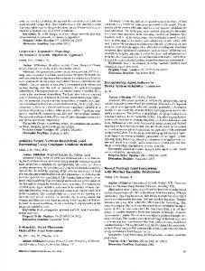
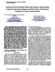
learning approach). The special feature of this controller is that the system adjusts it directly and on-line without making an explicit model of vehicle dynamics. Fujii ef al. [9]-[ 121 have been investigating neural network application to the control problems of Autonomous Underwater Vehicles (AUV’s) to fully display the advantage of the characteristics of neural networks. Thus, a neural-network-based control system called “Self-organizing Neural-net-Controller System: SONCS” [lo]-[ 121 has been developed as an adaptive control system for AUV’s to deal with their nonlinear dynamics and unknown environmental conditions. In this system, a neural network as a feedback controller is constructed through backpropagation method [6]. Although back-propagation method is one of the most general learning method for neural networks, it is not easy to adjust a neural network controller in real-time based on standard algorithm with limited computational power [15]. In this paper, an on-line adaptation method “Imaginary Training” is proposed to improve the adaptability of the SONCS. The original SONCS, as shown in Fig. 1, consists of a controlled object, a forward model network (FWD), a controller network, and evaluation and adaptation mechanism. The ) are controller network generates control signals ~ ( twhich passed to both the controlled object and the FWD. The FWD represents the forward dynamics of the controlled object and generates state variables of the next time step S f ( t At) when the control signals ~ ( tfrom ) the controller network and the measured state variables S e ( t ) are given as its inputs. The basic concept of this system is to adapt the controller network through the back-propagation process based on the differences between the motion data S f ( t ) emulated by the FWD and the reference signals r ( t ) . This adaptation process can be carried out by considering the controller network and the FWD as one network. The accuracy of control, therefore, depends mainly on how well the FWD can express the property of the controlled object. In the SONCS, an adaptation process is carried out by estimating a series of output state variables simulated by the FWD.The FWD needs input state variables given by the controlled object at each time step to generate a time series of state variables to be evaluated. The controller network, therefore, is revised only once after sampling a series of actual data. This means that the adaptation mechanism needs much time to generate a controller with a sufficient ability. Although the adaptability and effectiveness of the SONCS have been demonstrated in these years through several practical applications, for example, motion control of a cruising type
0364-9059/95$04.00 0 1995 IEEE
+
IEEE JOURNAL OF OCEANIC ENGINEERING, VOL. 20. NO. 3, JULY 1995
222
Adaptation U
-)
: control signals
-
-1
Sffr +A)
Se : stare variables (measured) Sf : state variables (outputs of FWD) r : reference signals
Fig. 1. Block diagram of original SONCS.
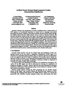
AUV called “PTEROAlSO [l]” along a sea bed topography [ 131, [ 141 and vibration control using a dynamic damper [ 161, the system’s flexibility is still limited because of this timeconsuming adaptation process. The Imaginary Training is introduced as an on-line adaptation method to reduce the time consumption of the adaptation process. The Imaginary Training is realized by introducing the new structure of the SONCS which consists of two separate processing parts: the Real-World Part and the ImaginaryWorld Part. In this structure, the controller can be adjusted independently of actual operation of the controlled object. The effectiveness of the Imaginary Training in the new SONCS is examined by applying to the heading keeping control of an AUV called “Twin-Burger’’ [ 171, [ 181. 11. ON-LINE ADAPTATION METHOD“IMAGINARY TRAINING” A. Parallel Structure
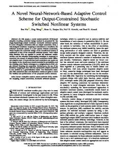
Fig. 2 shows the proposed structure of the SONCS. The SONCS is divided into two parts, the Real-World Part for the real control operation and the Imaginary-World Part for the adaptation of the controller network. The Real-World Part is an ordinary feedback system which consists of a controller ( C X) and a controlled object. The inputs to the C A are the differences between the reference signals r ( t ) and the state variables Se(t) given by the controlled object. The ImaginaryWorld Part consists of a controller (C1) which has the same structure as C R , and a FWD. The inputs to the C 1 are the differences between the reference signals r ( k ) and the state variables Sf(IC) which are calculated by the FWD. The inputs to the FWD are control signals u(k) given by the C1, where the time flow in the Imaginary-World Part is denoted by k which is independent of that of the Real-World Part. B. Introduction of the IdentiJcation Network The Identification Network [ 191 is one of the models which represent the motion of dynamical systems like a numerical model based on a set of differential equations of motion. Namely, the network calculates a time series of state variables Sf(k) when a set of initial values Sf(0) and a time series of external forces u(k)are given as its input signals. The Identification Network is introduced as the FWD in the proposed structure, because the network has equivalent
Imaginary Training U :control signals Se : state variables (measured) Sf : state variables (outputs of FWD) r : refmnce signals
Fig. 2.
Block diagram of improved SONCS.
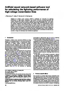
dynamics to the actual controlled object. The FWD, therefore, can generate a series of state variables to be evaluated without the measured state variables, which are indispensable to the controller adaptation mechanism in the original SONCS. As shown in Fig. 3, the Identification Network consists of three layers of neurons and two integration layers with two kinds of recurrent connections. A network with a layer for time-integration has been developed for the precise representation of dynamics [14]. This structure has been proved to be effective to prevent the network’s mapping function from converging to the identical mapping and to let the network acquire the capability of emulating the system’s behavior including higher-order finite differences. The Identification Network is, therefore, regarded as a model for representing the second-order difference equation. According to the definitions of the model in Fig. 3, the calculations in the integration layers are carried out to get a time series of S f ( k ) as described in the following. Let the neural network’s mapping function be f( ). The outputs from the third layer of the Identification Network are given by
A 2 S f ( k+ Ak) = f(ASf(k), ASf(k - Ak),-..,~(k), ~ ( -kArc),...). (1)
+
S f ( k Ak) can be calculated as the result of the following summation in the integration layers: ASf(IC
+ Ak) =
A2Sf(k)
(2)
k
(3)
-
ISH11 et al.: ON-LINE ADAPTATTON METHOD FOR AUV’S
223
C. The Imaginary Training
Ftegratiml
[Istl
[hdl
[3rdl
[lst]
The Imaginary Training can be executed independently of the actual control operation on the basis of the simulated motion data generated by the Identification Network and corresponding control signals given by the C 1 in the Imaginary-World Part. The synaptic weights of the CA are adjusted to reduce the evaluation potential function Ec:
[2nd]
EC = 1 / 2 c { ( r ( k ) - S f ( k ) ) T A . ( r ( k ) - S f ( k ) ) } . (7) e
k
Here, r ( k ) are the reference signals, S f ( k ) are the state variables given by the C 1, and A is the weighting matrix. The synaptic weights of the C X are replaced with those of the C_I when the adaptation of the C 1 has finished. Consequently, the Imaginary Training can be proceeded in the ImaginaryWorld Part independently of the actual world and the C X can be updated in parallel with the real control operation without waiting for measuring a set of actual data.
Sfnk+dR)
Fig. 3.
111.
Structure of the Identification Network.
APPLICATION OF THE IMAGINARY T R A I ” G
A. The Twin-Burger To simulate the motion by giving only Sf(0) and u(k), the outputs of the 1st integration layer ASf(k) is used as the inputs at the next time step. For this purpose, the state variables ASf(k Ak) in (2) are passed to the 1st layer via the recurrent connections (indicated by RC-1). The recurrent connections from the 2nd layer to the 1st layer (indicated by RCZ) allow the network to keep the influence of past data in itself and to express the dynamical behavior with reduced number of input state variables. The learning procedure of the Identification Network is divided into four stages considering the relationship the U 0 data. The cost function Ef and the inputs to the first layer for the each stage are defined in the following. Where, weighting matrices are denoted by Mi. Zst Stage: Inputs are ASe(k) and u(k), and evaluated outputs are A2Sf(k).
+
Ef = l/2c{(A2Sf(k) - AzSe(k))T. M I k
. (A2Sf(k) - A2Se(k))}.
(4)
and evaluated 2nd Inputs are Asf(k) and outputs are A2Sf(k). Ef is the same in (4). 3rd Inputs are Asf(k) and and evaluated outputs are ASf(k).
Ef = 1 / 2 c {(ASf(k) - ASe(k))T - M B k
. (Asf(k) - Ase(k))}. (5) 4fh Stage: Inputs are ASf(k) and u(k), and evaluated outputs are S f ( k ) .
Ef = 1 / 2 c { ( S f ( k )- Se(k))T.M4.( S f ( k )- Se(k))}. L
(6)
The performance of the improved SONCS is investigated through the application to the heading control problem of “Twin-Burger” [17], [18] vehicle shown in Fig. 4. The TwinBurger is an autonomous underwater vehicle designed as a versatile test bed for software development from the similar standpoint of EAVE I11 at the University of New Hampshire [20], Sea Squirt at M.I.T. [21], and AUV I1 at Naval Postgraduate School 1221. The vehicle has an open-frame-structured body and measures 1.54 m long and weights approximately 120 kg in air. Dimensions and specifications of the vehicle are shown in Table I. Most of the onboard instruments including the vehicle computer system, batteries, and other electronic circuits are mounted in a cylinder and twin FRP pressure hulls. The cylinder and FRP hulls are attached to the frame keeping high separation between the center of gravity and that of buoyancy, which produces a good static stability in rolling and pitching motion. The vehicle is propelled by 40 W thrusters in four-degrees-of-freedom control modes, i.e., surging, yawing, heaving, and swaying. A couple of thrusters located on both sides of the body_ parallel with the longitudinal _ axis controls the surging and yawing motion of the vehicle. In the following, the control input is the yaw moment induced by the difference of thrust of these two thrusters. A multiprocessor system based on N M O S Transputers [23] is adopted as the onboard computer system to realize the parallel processing. The parallel structure of the improved SONCS can also be realized easily by taking advantage of the parallel processing ability of the Transputer. The heading angle .JI and its rate A’$ are clockwise and the sampling and control rates are 10 Hz in the following experiments. B. Network Structure The network structure of the Imaginary-World Part to handle the heading motion of the Twin-Burger vehicle is designed as
IEEE JOURNAL OF OCEANIC ENGINEERING, VOL. 20, NO. 3, JULY 1995
224
Fig. 4.
The “Twin-Burger’’ vehicle. TABLE I DMENSIONS AND SPECIFICATIONS OF TWIN-BURGER
Breadth over all
0.65m
weieht
I 120ke
h D t h O v a dl
I
2hom (for CPUs)
Actuators
5 thrusters with 4OW DC motors 2 servo motors for camera pan and tilt Inertial navigation system Sensors 2 axes sped sensor Depth sensor CCD color imaging sensor 8ch. ultrasonic range findei Communication , Ultrasonic Command Link 1 Electro-luminescent panels Computer system < Main > 10 T800 Transputers
L
with 16Mbytes RAM c Interface >
4 T425 Transputers
-1.5
!
I
0
50
Time[sl
Fig. 6. Identification of the heading motion of the vehicle from the indicial response experiment.
C. Identijcation of the Vehicle Dynamics The FWD is constructed by learning from the teaching data of the actual motion of the vehicle. Here, the indicial response is adopted to get data of the heading motion of the vehicle. Fig. 6 shows the measured indicial response and the outputs of the constructed FWD.It is clearly shown that the property of the vehicle concerning the heading motion has been appropriately acquired by the FWD in spite of the noisy teaching data. It can be concluded that the Identification Network is suitable to extract the trend of the teaching data.
in Fig. 5. The FWD representing heading motion of the vehicle consists of seven neurons (including five recurrent neurons) in the 1st layer, five in the 2nd layer, and one in the 3rd layer. The inputs of the FWD are the heading rate A$(k) and the control moment u ( k ) . Consequently, the output in the 3rd layer is the heading acceleration A2$(k Ak) at the next time step. The C 1 consists of three neurons in the 1st layer, five neurons in the 2nd layer, and one in the 3rd layer. The inputs of the C_I D.Imaginary Training of the Controller are the differences between the reference signals ($,,(k) and The controller is easily initialized by learning a control Alltr(k))and the state variables ( $ ( k ) and A$(k)) given by action on the basis of a simple mapping function that is the FWD and the control moment u ( k - Ak) at the previous to force the vehicle to turn right when the heading angle time step. The output is the control moment u ( k ) generated is on the left of the target and vice versa (cf. Fig. 7). The by a couple of thrusters to control the heading motion of the experimental results controlled by the initialized controller and vehicle. the controller with the above rule are shown in Fig. 8. The
+
~
225
ISH11 ef al.: ON-LINE ADAPTATION METHOD FOR AUV'S
+
5.0
!
a
0.5
............
0
..............
Adaptation timcs
2000
Fig. 9. Transition of evaluation value. c
10 I
1
f
Fig. 7. Simple mapping function to initialize a controller.
- Initialkdwntroller
- Con~llerwithaimplemk
P I
-10
1 I I1 . --" I
I
I
i*."
I
X
pLL4I ...........................
--
.....
i
I
I
0 Tlme[S]
-1.0
!
I
I
-0 Time.[s]
I
Fig. 10. Comparison of emulated motion controlled by the adjusted controller and the initialized one.
20
Fig. 8. Experimental results controlled by the initialized controller and the controller with the simple rule.
initialized controller cannot make the vehicle converge to the target direction resulting in oscillations in the neighborhood of the reference heading angle, because the rule has not been tuned up well. The initialized controller is adjusted using the Imaginary Training process to reduce the evaluation value Ec which is defined to keep the state variables of the vehicle in the reference values as
Ec = 1 / 2 c { ( $ J ( k )-$J4q2 + (AdJ(k)-
20
(8)
k
Here, both $+-(IC) and A$J,.(Ic)are zeros. In every training, the initial heading angle and heading rate are fixed at 0.5 [rad] and 0.0 [radsec], respectively. The transition of the evaluation value is shown in Fig. 9 through 2000 times of the Imaginary Training. The outputs of the FWD controlled by the initialized controller and the adjusted one are compared in Fig. 10. It is clearly shown in these figures that the C_I is rapidly adjusted to an appropriate controller through approximately 500 times of Imaginary Training process.
IV. EXPERIMENTAL RESULTS Two kinds of experiments are carried out to examine the performance of the adjusted controller and to investigate the adaptability of the proposed system. A. Performance of the Controller
Experimental results when the vehicle is controlled by the C A replaced with the adjusted C_I in Fig. 10 are shown in Figs. 11 and 12. Here, the C R is not updated during the experiments. The vehicle is started with a small initial heading angle from the reference direction in Fig. 11. Although the external forces are given to the vehicle to disturb the motion at about 8 and 12 seconds, the vehicle is properly controlled to keep the reference direction. In the experiment of Fig. 12, the initial heading angle is about 0.5 [rad]. The vehicle succeeds in directing to the reference angle in 5 seconds performing the same motion emulated by the FWD in Fig. 12. Consequently, the proposed SONCS generates a suitable controller to keep the vehicle in the target direction with the Imaginary Training process. B. Adaptability of the SONCS The on-line controller adaptation experiments are carried out to investigate the adaptability of the proposed SONCS.
IEEE JOURNAL OF OCEANIC ENGINEERING, VOL. 20, NO. 3, JULY 1995
226
--WIh
I
I
Adsptption of C-I C-R update
Vehicle control (10th)
Fig. 13. Timing of data processing in the on-line adaptation experiment.
-3
1 Do
-1.0
20
0 Tme[s]
Fig. 11. Experimental results controlled by the adjusted controller (disturbances).
0 Time[s]
20
Fig. 12. Experimental results controlled by the adjusted controller (initial offset).
The Twin-Burger pursues a periodically changing reference signal in a condition that a constant moment generated by the thrusters is smultaneously applied to the vehicle instead of actual disturbances. The reference direction changes from +0.5 [rad] to -0.5 [rad] and vice versa every 10 seconds. The FWD is currently revised in order to deal with the change of the dynamical property of the vehicle induced by the constant applied moment (= 2.0 [Nm]). Teaching data for the FWD are sampled from the series of the state variables during the recent 20 seconds. The synaptic weights of the FWD for the
Imaginary Training are updated after 10 times of the learning (i.e., identification in Fig. 2) with these data. The Imaginary Training is concurrently executed using the newest FWD in parallel with other processes. The timing of data processing mentioned above is schematically shown in Fig. 13. Fig. 14 shows the results of experiments, i.e., control input, heading rate, heading angle, the estimation error (6) of the FWD and evaluation value (8) of the Imaginary Training. The vehicle is properly controlled to follow the reference signals in spite of the existence of the external force. Consequently, the C A updated with the C_I generates the counter forces to the disturbances in addition to the usual control forces to keep the target angles. This results from the input moment u(t - At) at the previous time step to the input layer of the C R . The recurrent connection from the output to the input of C A enables the controller to produce the control signal based on the time series of state variables. Figs. 15 and 16 show the outputs of the FWD without and with update, respectively. It can be seen that the FWD is properly adjusted by the additional identification based on the state variables obtained during the experiment. The trajectories in the Imaginary Training process are shown in Fig. 17. When II, = 0.5 [rad] and A$ = 0.0 [rads], the control output becomes -2.0 [Nm] which corresponds to the applied moment. Consequently, the on-line controller adaptation is realized and the improved SONCS has suitable adaptability to the change of control environment.
V. CONCLUSIONS In this paper, the new structure of Self-organizing Neuralnet Controller System which has two separate parts, the Real-World Part and the Imaginary-WorldPart,is proposed for the on-line controller adaptation. The adaptation method called “Imaginary Training” can be executed in the Imaginary-World Part independently of the actual operations by introducing a neural network model called “Identification Network” as the forward model network. The controller in the Real-World Part can acquire the appropriate function rapidly by replacing the synaptic weights with those of the adjusted controller in the Imaginary-World Part. The effectiveness of the improved SONCS with the Imaginary Training was examined through the application to the heading keeping control of an AUV “Twin-Burger.” The Identification Network is able to simulate the heading motion of the vehicle sufficiently well in spite of the noisy teaching
ISH11 et al.: ON-LINE ADAFTATION METHOD FOR AUV’S
B
i
I
U
1.0
,
I
I
I
I
I
I
-1.0 I
I
I
1
I
20
0 TWSI
Fig. 16. Comparison of the FWD and experimental results when constant forces are given to the vehicle and the FWD is revised.
Tme[s]
Fig. 14. An on-line adaptation experiment when constant external forces are given to the vehicle.
i n
E
t I
-to!
B B
Twet aaslc
20
Tme[s]
Fig. 17. Performance of the controller C 1 in the Imaginary Training when constant forces are given to the vehicle.
f -0.2
-.-I
-1.0
-1.0 0
!
0
i
I
I
, Tme[s]
Fig. 15. Comparison of the FWD and experimental results when constant forces are given to the vehicle and the FWD is not revised.
data. An appropriate neural-net controller for the heading motion is generated through the Imaginary Training process. The proposed structure is enhanced taking advantage of the parallel processing capability of the vehicle. The experimental results show that the controller has a good performance to keep the vehicle in the target direction.
The proposed control system shows good adaptability and the robustness against the change of the dynamical property and the control environment. It can be concluded that the online controller adaptation method using “Imaginary Training” is one of the promising systems to establish a sophisticated adaptive controller for a wide variety of applications especially when the target system has a computer system with the parallel processing capability. REFERENCES T. Ura, “Free swimming vehicle PTEROA for deep sea survey,’’ in Proc. ROV’89, 1989, pp. 263-268. Y. Ito, N. Kato, J. Kojima, S. Takagi, K. Asakawa, and Y. Shirasaki, “Cable tracking for autonomous underwater vehicle,” in Proc. A W ’ 9 4 , 1994, pp. 218-224. D. N. Yoerger and J. E. Slotine, “Robust trajectory control of underwater vehicles,” IEEE J. Oceanic Eng., vol. 10, no. 4, pp. 462470, 1985. 1
228
141 D. N. Yoerger, J. G. Cooke, and J. E. Slotine, “The influence of thruster dynamics on underwater vehicle behavior and their incorporation into control system design,” IEEE J. Oceanic Eng., vol. 15, no. 3, pp. 167-178, 1990. [51 R. Cristi, F. A. Papoulias, and A. J. Healey, “Adaptive sliding mode control of autonomous underwater vehicles in the dive plane,” IEEE J. Oceanic Eng., vol. 15, no. 3, pp. 152-160, 1990. I61 D. E. Rumelhart, J. L. McClelland, and The PDP Research Group, Parallel Distributed Processing. Cambridge, MA: The MlT Press, 1986. J. Yuh, “A neural net controller for underwater robotic vehicles,” IEEE J. Oceanic Eng.. vol. 15, no. 3, pp. 161-166, 1990. -, ‘‘Learning control for underwater robotic vehicles,” IEEE Control Sys?.Mag., vol. 15, no. 2, pp. 3 9 4 6 , 1994. T. Fujii and T. Ura, “Control with neural network for autonomous underwater vehicle,” J. Soc. Naval Arch. Japan, vol. 166, pp. 503-511, 1989, in Japanese. -, “Development of motion control system for AUV using neural nets,” in Proc. IEEE AUV’90, 1990, pp. 81-86. 1111 T. Ura, T. Fujii, Y. Nose, and Y. Kuroda, “Self-organizing control system for underwater vehicles,” in Proc. IEEE OCEANS’W, 1990, pp. 7-1. 1121 T. Fujii and T. Ura, “SONCS: Self-organizing neural-net-controller system for autonomous underwater robots,” in Proc. IEEWINNS IJCNN’9I, 1991, pp. 1973-1982. [I31 T. Suto and T. Ura, “Unsupervised learning system for vehicle guidance constructed with neural network,” in Proc. 7th UUST, 1991, pp. 203-2 12. [14] T. Suto and T. Ura, “Unsupervised learning system for vehicle guidance constructed with neural network (2nd report: Modification of forward model and adaptation process),” in Proc. 8th UUST, 1993, pp. 222-230. [I51 K. Ishii, T. Fujii, and T. Ura, “A quick adaptation method in neural network based control system for A m ’ s , ” in Proc. A W ’ 9 4 , 1994, pp. 269-274. [ 161 Y. Kuroda, T. Ura, and S. Morishita, “Damping-controllable dynarmc damper with neural network based adaptive control system,” in Proc. IEEWINNS IJCNN’91, 1991, pp. 1807-1812. [I71 T. Fujii, T. Ura, and Y. Kuroda, “Mission execution expenment with a newly developed AUV the twin-burger,” in Proc. 8th UUST, 1993, pp. 92-105. [I81 T. Fujii, T. Ura, Y Kuroda, H. Chiba, Y. Nose, and K. Aramalu, “Development of a versatile test-bed “twin-burger” toward realization of intelligent behaviors of autonomous underwater vehicles,” in Proc. IEEE OCEANS’93, 1993, pp. 186-191. [19] K. Ishii, T. Ura, and T. Fujii, “A feed forward neural network for identification and adaptive control of autonomous underwater vehicles,” in Proc. IEEE ICNN’94, 1994, pp. 3216-3221. 1201 S. G. Chappell, “A backboard based system for context sensitive mission planning in an autonomous vehicle,” in Proc. 5th UUST, vol. 2, 1987, pp. 467476. [21] J. Bellingham, T. Consi, and R. Beaton, “Keeping layered control simple,” in Proc. AUV’90, 1990, pp. 3-9.
IEEE JOURNAL OF OCEANIC ENGINEERING, VOL. 20, NO. 3, JULY 1995
1221 A. J. Healey and D. B. Marco, “Experimental verification of mission planning by autonomous mission execution and data visualization using the NPS AUV U,” in Proc. AUV’92, 1992, pp. 65-72. [23] The Transputer Databook, 2nd ed. INMOS Limited, 1989.
Kazuo Ishii was born in Japan in 1969. He received B.E. and M.E. degrees in naval architecture and ocean engineering from the University of Tokyo in 1991 and 1993, respectively. He is pursuing the Ph.D. at the Institute of Industrial Science, the University of Tokyo, under the supervision of Prof. Tamaki Ura. His research interests include underwater robotics and neural networks.
Teruo Fujii was born in Switzerland in 1964. He received B.E., M.E. and Ph.D. degrees from the Department of Naval Architecture and Ocean Engineering at the University of Tokyo in 1988, 1990, and 1993, respectively. He is currently an associate professor at the Institute of Industrial Science, the University of Tokyo, where he had been in the TOYOTA endowed chair as an associate professor of Globe Engineering from 1993 to 1994. He is currently with the Chenucal Engineenng Laboratory at the Institute of Physical and Chemical Research (RIKEN). His research interests cover intelligent ocean exploratory systems, underwater robotics, neural network based advanced control system, distributed intelligence, and Meta-Biotics.
Tamaki Ura received B.S., M.A., and Dr. of Engineering degrees from the University of Tokyo. He is a professor of the Institute of Industrial Science at the University of Tokyo. His current interests are in the fields of underwater robotics, intelligent control, deep sea survey, and granular mechanics relating to transport in bulk. Dr. Ura is a recipient of the Best Paper Award in 1979, the Invention Award in 1994 from the Society of Naval Architects of Japan (SNAJ), and the Houkou Award in 1982, and the c h a m a n of the underwater system committee of SNAJ.