Journal of Simulation (2011) 5, 147–156
r 2011 Operational Research Society Ltd. All rights reserved. 1747-7778/11 www.palgrave-journals.com/jos/
An ontology-enabled user interface for simulation model construction and visualization Z Ezzell1*, PA Fishwick1, B Lok1, A Pitkin2 and S Lampotang2 1 Department of Computer Information Science and Engineering (CISE), University of Florida, Florida; and 2Department of Anesthesiology, University of Florida, Florida
The purpose of an ontology is to structurally define knowledge about a topic. For the practice of simulation, ontologies have been demonstrated to be useful across a variety of techniques ranging from formally defining the components of dynamic models and capturing key simulation domain constraints to interrelating dynamic model components and geometry in order to visualize a phenomenon. We have created a methodology that requires domain ontologies to be rendered in the human-interface layer in support of the construction of dynamic models and their corresponding visualizations. We hypothesize that this methodology will provide a novel and accessible way to author visualizations and a framework for creating new teaching tools that merge concrete and abstract knowledge. A case study of our methodology is performed by applying our software prototype to simulation and visualization in the domain of healthcare, specifically cardiovascular physiology Journal of Simulation (2011) 5, 147–156. doi:10.1057/jos.2011.5; published online 25 February 2011 Keywords: ontology; simulation; visualization; semantic web
1. Introduction Ontologies are being used across various fields and are increasing in popularity (Zhou, 2007). The concept of an ontology is defined by Gruber (1993) as a ‘specification of a conceptualization’; however, the word ‘ontology’ has different connotations depending on community of practice. For some with a more restricted definition, a conceptual shared knowledgebase is not an ontology unless it contains a host of complementary features (eg, attributes, relations, restrictions, rules, and events). When we speak of an ontology, we are referring to a hierarchy of subsuming concepts supplemented with semantic relations that further define how concepts are interrelated (Tolk and Turnitsa, 2007). For instance, in a case study for this work, we leverage the Foundational Model of Anatomy Ontology (FMAO) (Rosse and Mejino, 2007), which defines anatomical concepts using mostly ‘is part of ’ relationships. Another example is the Discrete-event and Modeling Ontology (DeMO) (Miller et al, 2004) that formalizes concepts within the domain of discrete-event simulation using a variety of relationship types, such as ‘is a’, ‘has’ and ‘uses’. In addition to DeMO, there has been much interest in ontologies within the simulation community. For instance, ontologies are now well-known to support interoperability (Lacy, 2006) and composability (Tolk, 2006), and they have aided in the construction of both monolithic (Silver et al, *Correspondence: Z Ezzell, 3813 SW, 34th ST, APT 27, Gainesville, FL 32608, USA. E-mail:
[email protected]fl.edu
2007) and distributed (Benjamin et al, 2006) simulation and visualization systems. Few, however, have placed ontologies in the user interface (Paulheim and Probst, 2010). We hypothesize that ontologies may be useful if manifested in the user interface, specifically to aid in simulation model design and visualization construction. This paper presents a methodology that visualizes ontologies as graphs in the user interface to facilitate the construction of dynamic models and their corresponding three-dimensional (3D) visualizations. Historically, there are several phases required to build a dynamic 3D visualization. One must start with a dynamic model of the phenomenon to be simulated. This model is created from scratch or by starting with a pre-existing model found in literature, and follows some modelling paradigm (eg, compartmental modelling). Given the model, software design decisions must be made on how to map model components to software components using some programming paradigm (eg, object-oriented or visual programming). Finally, the visualization software must be implemented, either concurrently with the design stages, or afterwards. The time and resources required by this process can be reduced by merging simulation model design with visualization construction. Our methodology utilizes domain ontologies as an interface affordance to facilitate this merger. Naturally, this work will contribute to the growing body of research concerned with the application of ontologies to modelling and simulation. However, our work can also be situated in the burgeoning field of integrative multimodelling. The goal of this new field is to merge multiple model types in a meaningful way within a single interface (Fishwick, 2004).
148 Journal of Simulation Vol. 5, No. 3
Preliminary work has been done in integrative multimodelling, including the framework created by Park and Fishwick (2005), and the mixed-reality simulator created by Quarles (2009). In Section 2, we will elaborate on these integrative multimodelling efforts, and present a background on how ontologies are being used in simulation. Section 3 contains a discussion of open issues in medical training, an area which may benefit from our ontology-centric methodology. Using an example from the medical domain, our methodology is applied in a step-by-step manner in Section 4. Finally, conclusions and future directions are presented in Section 5.
2. Background In this section, a wide view of ontology research in simulation and modelling will be presented, followed by an in-depth discussion of the domain ontology and integrative multimodelling research most influential to our work. ‘The Semantic Web’, the seminal 2001 Scientific American article, depicted a future of the Internet where reasoning is employed over vast ontologies, composed of classes and relationships, in the support of a more intelligent browsing and searching experience for users (Berners-Lee et al, 2001). A variety of new knowledge-based applications would also emerge. Nearly a decade later, the proliferation of the Semantic Web via such standards as the Resource Description Framework (RDF) is debatable, but there is no doubt ontologies have become useful in many ways. In biological sciences, for instance, the Gene Ontology Project, created by a consortium of biological scientists to aid in the construction of a unified vocabulary across different biological domains, has been very successful and continues to grow (The Gene Ontology Consortium, 2010). The DeMO was created to support the simulation community (Miller et al, 2004). DeMO was built in the ontology editor Prote´ge´ (Noy et al, 2001) with the help of the OWL plug-in for enhanced reasoning ability (Knublauch et al, 2004). The ontology contains three top-level classes: DiscreteEventModel, ModelComponent, and ModelMechanism. Under these three classes is a collection of subclasses representing the necessary concepts within discrete-event modelling. For instance, two subclasses of DiscreteEventModel are State-OrientedModel and Event-OrientedModel. ModelComponent has corresponding subclasses state and event. The authors of DeMO concede that the classes such as state and event are fundamental concepts and will require further formal specifications that are implementation-specific. However, once users of DeMO provide these specifications for the ‘primitive’ types, they can leverage the entire machineunderstandable DeMO semantic network. A goal of authors of ontologies such as DeMO is to improve the process of discovery through an enhanced browsing experience and faster and more intelligent queries.
Discovery can be enhanced by providing a component-based view of a system where one may choose desired components to build a simulation engine piece-by-piece (Chandrasekaran et al, 2002; Bell et al, 2008). Further, DeMO can facilitate the automation of simulation application development through inference and reuse of ontology components, thus decreasing application development time. This is touted as a core offering of ontologies to the field of modelling and simulation (Lacy and Gerber, 2004). Taylor et al (2010) developed a theoretical framework and software prototype that permits discovery by allowing the user to perform a semantic search through an ontology of simulation concepts and packages using a web-service interface. Search results can be used to piece together an ad hoc simulation solution that reuses pre-existing components and relies heavily on interoperability and multimodelling. The unambiguous identification of conceptual model components is another benefit of ontology-centric design and is a requirement to improve interoperability between components in simulation systems (Miller and Baramidze, 2005; Tolk and Turnitsa, 2007). Of the previous applications of ontologies to simulation systems, we draw the most inspiration from those that utilize domain ontologies. Silver et al (2007) developed the ontologydriven simulation framework. Their framework utilizes domain ontologies along with DeMO and consists of an ontology mapping tool, a model markup generator, and a simulation code generator. The ontology mapping tool allows users to map classes of the domain ontology to classes in the simulation ontology. Their design suite was demonstrated starting with the problem-oriented medical records ontology (PMRO) to build a clinical simulation. Examples of mappings in this scenario include mapping the class Patient in PMRO to the class Resource in DeMO, and mapping the class ClinicalExamination in PMRO to the class Activity in DeMO. After the domain ontology is aligned with the simulation ontology, an intermediate markup file can be generated that represents the simulation instance as either a Petri Net model or a process interaction model. This intermediate markup file can then be translated into executable models that run in JSIM (Miller et al, 2000) or ARENA. Silver et al describe four main benefits of the ontology-driven approach: (1) The use of a shared vocabulary facilitates good communication between modellers and end-users. (2) Models created for different simulation packages using different simulation world views can be represented in a unified language. (3) Models are encoded in a Semantic Web compatible language, thus supporting potential web-based model repositories and web-component-based simulation systems. (4) Model development can be sped up by allowing modellers to assemble models by using a set of predefined classes represented in the domain-specific and simulation ontologies. Manifesting ontologies in the interface, as in the framework developed by Silver et al, is an example of integrative multimodelling (Fishwick, 2004). Integrative multimodelling
Z Ezzell et al—Ontology-enabled user interface 149
calls for a closer linkage between the abstract model and the phenomena which it represents. One way to achieve this is to graphically represent the abstract model and phenomena within one cohesive interface and allow user interactions on graphical representations of both. This new representation technique also has four main human-computer interaction requirements: usability, emotion (by means of connotation), immersion, and customization. An early application of the principles of integrative multimodelling is the work done by Park and Fishwick (2005). A framework was created that allowed for the integration of different model types (ie, dynamic, interaction, ontological, and geometric) within a 3D simulation environment. The prototype they created in Blender (http://www.blender3d.org, accessed 15 March 2010 is composed of a Model Explorer for dynamic modelling and an Ontology Explorer with OWL integration so that users can create OWL classes and subclasses. They utilized the RUBE simulation library (Hopkins and Fishwick, 2002) to aid in the building of dynamic models and execution of simulations. Users of their prototype can create geometry using Blender or import pre-existing meshes. Dynamic model components (eg, blocks within a Functional Block Model) can be selected from RUBE and associated with geometry in the scene. Using Blender Game Engine functionality, an interaction model can be created and linked with geometry. Quarles et al (2008) applied integrative multimodelling to anaesthesia training by creating a mixed reality training tool that collocates abstract models used to teach anaesthesia machine operation with components on a physical anaesthesia machine. The tool, known as the Augmented Anesthesia Machine (AAM), uses a ‘magic lens’ interface. This interface is a tracked tablet PC that serves as a window into the real world. Users hold the tablet PC in front of the physical anaesthesia machine and see a 3D rendering of the machine on the display from the perspective of the tablet. On top of this 3D rendering, the abstract model is visualized using iconography, and invisible gas flow within the machine is visualized using colour-coded particle systems. User studies were performed that compared the AAM to traditional training methods (eg, instruction manuals) and web-applets that used abstract visualizations. The results of the study showed that the AAM was most successful at bridging the gap between abstract and concrete knowledge, thus proving the approach is a potentially viable educational technique that should be explored further (Fischler et al, 2008). The creators of the AAM point towards the use of ontologies as a way to define a theoretical framework for such mixed-reality systems (Quarles, 2009). We elucidate on how we build upon the work of Park and Fishwick (2005) and Quarles (2009) in Section 4, followed by a description of our methodology.
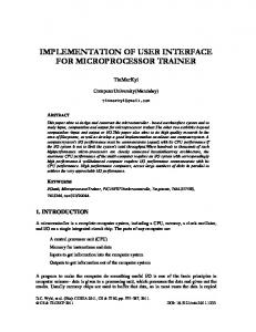
3. Training in healthcare The case study used to demonstrate our methodology comes from the domain of medical education and training. This section is dedicated to detailing some of the open issues in this area that our methodology could address. In healthcare, human error is one of the main causes of preventable deaths and injuries, as illuminated by the landmark report ‘To Err is Human’ (Kohn et al, 2000). For example, a study showed that human error accounted for 82% of anaesthesia-related preventable deaths (Cooper et al, 2002). Since the release of ‘To Err is Human’, strides have been made to increase patient safety by reducing human error. However, there is still much need for improvement, especially in the area of training (Leape et al, 2009). Many junior physicians feel they have had insufficient exposure to uncommon conditions and procedures before embarking on independent practice (Mason and Strike, 2003). The new medical training paradigm should integrate competencybased knowledge with clinical skill and expose trainees to more uncommon conditions (Rodriguez-Paz et al, 2009). Consider a common source of human error: the administration of drugs to patients. Adverse drug effects (ADEs) are a primary reason patients die in a hospital (Bates et al, 1995). As a result of the intricate and complex nature of the cardiovascular system, cardiovascular drugs are known to cause the most ADEs (Ebbesen et al, 2001). Even more difficult for trainees to understand is the varying effects drugs and other medical interventions have on patients with abnormal circulatory physiology. For example, hypoplastic left heart syndrome (HLHS) is a congenital heart defect in which some chambers of the heart fail to develop. HLHS results in abnormalities of blood flow and oxygen delivery that can be difficult for the learner to visualize and therefore understand. As a result, certain interventions which are helpful in patients with normal circulation, such as the administration of oxygen, may be harmful in an infant with HLHS. New training paradigms that integrate simulation with traditional teaching methods will help trainee physicians avoid making harmful errors because of their lack of understanding of a rare and complex pathophysiology. We believe our methodology can address the needs of this newly proposed medical training paradigm. Starting with an ontology, medical educators should be able to construct a dynamic model, such as the Beneken (1965) model for cardiovascular physiology shown in Figure 1, and then create a 3D visualization of the physiological process by augmenting the visualized ontology with attributes, such as 3D meshes. A possible result of assigning visualization attributes to members of the ontology is shown in Figure 2. The model building and 3D interaction within integrative visualizations could expose medical trainees to more uncommon conditions and integrate their textbook knowledge of anatomy and physiology with interactive 3D renderings, potentially increasing their spatial understanding
150 Journal of Simulation Vol. 5, No. 3
Figure 1 The compartmental for cardiovascular physiology proposed by Beneken (1965).
Figure 2 A 3D visualization of an infant with heart, lungs, arteries, and veins exposed.
of the anatomy and physiology in question (Beermann et al, 2010).
4. Methodology In this section, a comparison of our methodology with two notable integrative multimodelling efforts is presented. This is followed by a step-by-step explanation of our method of manifesting ontologies in the user interface in support of dynamic model construction and visualization. Park and Fishwick (2005) developed an integrative multimodelling framework that leveraged ontologies. They created a holistic ontology composed of classes pertaining to concepts in simulation, visualization, and the domain of interest (eg, military or chemistry). Portions of the ontology were represented in the interface as lists. This enabled users
to fill-in some required information (eg the name of a ‘.obj’ file or type of model: Functional Block Model or Finite State Machine). However, the ontology was not displayed within the visualization environment, leaving the integrative visualization to be composed solely of graphical and dynamic models. Our work builds on this framework by placing the domain ontology in the integrative visualization along with the dynamic and graphical models. Further, this allows us to use the representation of the ontology as an affordance for authoring dynamic models and corresponding visualizations, something not possible in the framework defined by Park and Fishwick. Quarles et al (2008) showed the AAM to be effective in some areas of training. However, no formal method was provided to create similar style visualizations for different processes. Our methodology is a first step toward defining a conceptual framework for building tools such as the AAM. With domain ontologies manifested in the visualization environment, dynamic models can be constructed by supplementing the domain knowledge with new ‘dynamics’ information and visualizations can be built by adding visual attributes to the members of the ontology. The 3D collocation required by the AAM will come naturally in our methodology because the abstract knowledge (ie, the ontology) and dynamic model are used as interface affordances and, therefore, manifested in the 3D visualization environment from the start. In the remainder of this section, we describe our prototype ontology viewer, dynamic model builder and visualizer. In Table 1, we codify our usage of ontologies in the interface according to the classification system presented by Paulheim and Probst (2010). The ontologies that are well-suited for our methodology leverage ‘real world’ semantics (eg, anatomy), but there is no semantic complexity requirement on them. The visualized ontology can be leveraged during design time (eg, to build a dynamic model) or run time (eg, to label components and denote relationships). Further, ontologies are visualized as graphs and textual labels serve to ‘verbalize’ ontology members. Finally, our methodology allows interaction as a means to change which ontology members are visible and to modify the ontology within the visualization environment. The software prototype used to demonstrate our methodology is coded in C++. Custom interface components and 3D graphics rendering are performed using the OGRE rendering engine (http://www.ogre3D.org, accessed 15 March 2010). In our prototype, users can control the perspective by rotating and translating the 3D camera using mouse controls. Figure 3 shows a screen shot of our software tool with the interface components labelled. Interface components are docked to the left side of the screen and can be expanded and collapsed. To describe the functionality of our prototype, we will present five steps that cover its primary uses. First, users build an ontology by (1) creating nodes, (2) forming relationships between nodes, and (3) assigning
Z Ezzell et al—Ontology-enabled user interface 151
Table 1 The characteristics of our ontology usage (highlighted in tint) as defined by the classification system created by Paulheim and Probst (2010) Characteristics
Classifications
Domain Complexity Usage Visualization Interaction
Real world Informal Design time None None
IT systems Low Run time List view
Figure 3 A screen shot of our software revealing the main interface components. (a) The View Options Pane for changing view settings. (b) The Loading Pane for loading XML files. (c) The Node Creator Pane for adding ontology nodes. (d) The Simulation Pane for executing simulations. (e) The Ontology Pane for expanding and collapsing ontology nodes. (f) The Attribute Pane for setting attributes of ontology nodes. (g) A visualization of an infant and anatomy. (h) The ontological nodes for scene and infant, connected by a ‘has a’ relationship (ie, the scene has an infant) that is denoted by a blue edge. The sub-ontology rooted at infant is collapsed and, therefore, not shown.
attributes to the nodes. Then, (4) a dynamic graph that represents a compartmental model is created on top of the ontology. Finally, (5) a simulation is executed and simulation variables are plotted.
4.1. Step 1: Obtaining an ontology If an ontology is a requirement to build a dynamic model and construct a visualization, then the question arises of where this ontology comes from. Our software prototype is open-ended in this regard by allowing users to load an ontology from a file or author an ontology from scratch by adding nodes and forming named relationships between them. Further, this methodology could be applied to ontologies of any semantic complexity. For instance, a
Users and roles Medium Graphical View and edit
High Verbalized
Source code
medical practitioner building physiological simulations and visualizations may start with the FMAO (Rosse and Mejino, 2007). FMAO is a vast ontology representing anatomical concepts and the relationships between them. Figure 4 shows a portion of the ontology pertaining to cardiovascular function, and demonstrates the hierarchal nature of the ontology and some of the relationship types within. Figure 5 shows the specific sub-ontology we use to demonstrate our methodology. The ontology was in XML to be loaded into our prototype. If users wish to create or augment an ontology, they can do so by using the Node Creator Pane, shown in Figure 3, by entering the name of the node they wish to create and then pressing the create button. A new node with the name given by the user will appear at the origin. When a node is selected, users can view the attribute menu for that ontology member and a 3D mover tool appears that is rooted at the selected node. The mover tool allows users to move the node in the X, Y, and Z directions.
4.2. Step 2: Creating relationships between nodes To form relationships in the ontology, users employ the graphical interface to add semantic edges between nodes. This is done by holding down the left mouse button while the cursor is over a node for a short time until the icon for the Edge Creator Tool appears over the cursor. Users can then drag the Edge Creator Tool to the node they wish to connect to. When the left mouse button is released over a node, an edge is formed, thus creating a relationship in the ontology. The relationships in the example ontology of the heart are of the type ‘has a’; however the type can be changed by selecting the edge and changing the name of the relationship in the Attribute Pane. After relationships are formed, ontology nodes can be expanded or contracted based on the relationship type. This function is performed in the Ontology Pane, shown in Figure 3. The expanded sub-ontology of ‘has a’ relationships for the heart is shown in Figure 6a. All of the hearts subcomponents become visible (eg, vena cava, aorta, etc). The heart ontology node is a subcomponent of the infant ontology node, which accounts for the edge leading off screen in Figure 6a.
152 Journal of Simulation Vol. 5, No. 3
Figure 4 A portion of the foundational model of anatomy ontology (FMAO) (Rosse and Mejino, 2007). The three dots indicate more ontology classes are present in FMAO than depicted here.
Figure 5 The sub-ontology, created from concepts in FMAO, that is loaded into our software prototype in order to demonstrate our methodology. Abstract classes are shown in rectangles and instances are shown in rounded rectangles. Relationships are of type ‘has a’ or ‘is a’.
4.3. Step 3: Adding attributes to ontology nodes Each of the nodes representing members of the ontology serve as an interface to attributes of that member. When users select a node, attributes become visible in the Attribute Pane, shown in Figure 3, for that ontology member. The Attribute Pane contains a menu that lists all the attributes of the selected member. Items in the attribute menu can be thought of as terminal members of the
ontology. Users can modify entries in the attribute list, or create new entries. For example, abbreviation is a userdefined attribute that can serve as a shorter label for nodes when the camera is far away in order to simplify the interface. The attribute menu also the interface that allows users to add visual components to nodes in order to create a complete 3D visualization. When users create a new attribute called mesh or material, our system interprets it appropriately. For efficiency, once an attribute is created for
Z Ezzell et al—Ontology-enabled user interface 153
Figure 6 (a) A view of a sub-ontology for the heart. The heart node is expanded; therefore, all of its subcomponents are visible. The heart is a subcomponent of the infant node, which accounts for the edge leading off screen; (b) the same view of a sub-ontology for the heart shown in Figure 6a but with meshes and textures assigned to ontology nodes.
one node (eg material ¼ heart_material), it can be dragged and dropped to other nodes as a way to copy attributes. 3D meshes in our system need to be specified in the OGRE .mesh format. Materials should be specified in the OGRE material format and defined in a .material file. We export meshes and materials into these formats using a plug-in to Blender. Figure 6b shows the result of assigning the meshes and materials to members of the heart sub-ontology. When meshes are loaded into our system, they stay rooted to the node they are assigned to. Users can move the mesh by using the 3D mover tool attached to the node. Positional offsets of meshes from nodes can also be added by adding the attribute node offset to a given node. Figure 2 shows the complete visualization of an infant with heart, lungs, arteries and veins, and with all meshes moved to their correct positions.
4.4. Step 4: Creating a dynamic model After loading or building an ontology and using it to create a visualization, we can define a compartmental model. This is done by adding new dynamic edges between nodes of the ontology. Edges are added using the Edge Creator Tool described in Step 2. An edge can be either a semantic edge (ie, part of the base ontology) drawn in blue, as defined in Step 2, or a dynamic edge (ie, part of a compartmental model that is added to the ontology) drawn in red. After an edge is added, users can select it and change its type in the Attribute Pane. The compartmental model we add in this example is defined by Goodwin et al (2004), a variant on the Beneken (1965) model shown in Figure 1, and is tuned for the cardiovascular system of an infant. The model uses differential equations to represent blood flow through the body. The connectivity of the model is recreated in our system by adding the appropriate dynamic edges between ontology members. Dynamic models can be morphed into a 2D layout, similar to the format found in textbooks. The 2D
layout may provide a better insight into the connectivity of the abstract model. Morphing occurs though a fluid animation between the collocated 3D graph and the 2D layout. A depiction of this morphing is shown in Figure 7. On the left of the figure is an illustration of the morph for the sake of clarity. On the right of the figure is the morphing as depicted in our interface. Currently, 2D positions of nodes are hard-coded because all the processes we have modelled share the same circular configuration and have similar compartments (ie, components of the circulatory system). Applying first-order logic to the relational semantics embedded in ontologies can benefit the software development process and reduce input required by users. We are currently exploring ways to reason on domain ontologies to automate portions of the dynamic model creation. Consider FMAO, a portion of which is shown in Figure 4. Notice the ontology class heart has a relationship typed ‘has arterial supply’. This relationship can be used to construct a dynamic model representing blood flow where left coronary artery and right coronary artery would be placed as inputs of the heart. Conversely, the relationship typed ‘has venous drainage’ would place systemic venous tree organ as an output of the heart. We are also exploring the use of reasoning to automatically tailor user experiences. Using a reasoner, we could equate the relationship ‘has part’ to a labelling depth. The desired depth of anatomy labelling could be provided by the user. Given this depth, the visualization of the ontology could be expanded or contracted appropriately. For instance, expanding the ontology node for the heart would reveal its two parts: left side of heart and right side of heart. The user could continue to increase the labelling depth until all parts of the heart present in FMOA are labelled within the visualization. Users could also choose to keep a highlevel view of the anatomy and decrease the labelling level until just the label for heart is visible.
154 Journal of Simulation Vol. 5, No. 3
Figure 7 (left) An illustration of the morphing between the collocated Goodwin et al (2004) model and the 2D layout of the same model. (right) The same views of the model within our interface.
4.5. Step 5: Simulation execution The simulation can be executed after the visualization parameters are finalized and the dynamic model is defined. A typical set of equations for a compartment in the Goodwin et al (2004) model accounts for blood pressure, flow, and change in volume. In our methodology, these simulation variables become attributes of the ontology nodes. Currently, we provide a small C++ code module that is used to solve all the necessary differential equations. Owing to the small time-step required to ensure numerical stability when solving the differential equations, the simulation is run in a thread separate from the visualization. Simulation control options are located in the Simulation Pane, shown in Figure 3. In order to run the simulation, users are presented in the interface with options to play, pause, or reset ‘Infant Cardio Physiology’. Play will begin to update values at each time step. Pause will suspend the simulation at the current time but allow for continued play in the future. Reset will set the simulation time to zero and set all variables to their initial state. Once the model is running, users can choose to add 2-s time plots of different variables to the visualization by dragging the desired variables from the attribute menu into the scene. The plots are connected to the nodes which they represent and stay rooted to them in 3D space (ie, when the
camera moves the plot will maintain its 2D position with respect to the node). This is similar to the 3D anchoring of virtual instruments in process visualizations presented by Matkovic et al (2002). The plots for blood volume and pressure for the right atrium node are shown in Figure 8.
5. Future work and conclusions We plan to develop our methodology to further exploit the ontological format in the creation of dynamic visualizations and dynamic models. We are currently working to build an equation repository that would allow visualization creators to easily integrate the necessary set of equations into the visualized domain ontology. Users should be able to apply equations to ontology nodes as an attribute in order to simulate different physiological processes or pathologies (eg, the change of blood volume with respect to time). Further, because the equations used are of a standard form, which differ only in coefficients, we can create a general solver that takes coefficients as input. There are many examples of pathology models that share the same components and differ only slightly in connectivity and placement of resistance functions and valves. For instance, the models for the two pathologies patent ductus arteriosus and Tetralogy of Fallot (Sa´ Couto et al, 2006) are very similar to the base Beneken
Z Ezzell et al—Ontology-enabled user interface 155
Figure 8 (left) A running simulation of infant cardiovascular physiology with plots for the variables blood volume and pressure of the right atrium. (right) A close-up view of the variable plots.
(1965) model. With an equation repository, users could quickly create a visualization of one pathology if given another. In order to explore our methodology within more semantically complex scenarios, we plan to add support for additional ontology formats, such as RDF, a standard for conceptual-level domain descriptions. RDF support could enhance our current case study of visualizing physiology by adding the ability to import established, agreed-upon ontologies such as FMAO. Further, with RDF support we could import a vast array of ontologies into our prototype and perhaps demonstrate our methodology within a domain other than healthcare. We have detailed our current methodology and software prototype. Our development thus far has consisted of deploying an ontology-centred design philosophy in an attempt to further explore the virtues of integrative multimodelling. Our specific solution uses an ontology-enabled interface as a starting point to build compartmental models and dynamic visualizations. Visualizations can be developed by adding visual attributes, such as 3D meshes and materials, to members of a domain ontology. Compartmental models can be created by adding dynamic edges between members of an ontology to signify flow. After the visualization layout and compartmental model construction, a simulation can be executed that solves the differential equations at each compartment of the model in real-time. Further, we are currently exploring ways to reason on the domain ontologies to automate portions of this process. Upon further development, our methodology will be useful for medical educators as a way to supplement their current teaching methods of physiology. We are currently designing user studies that compare traditional teaching media (eg, lecture slides on pathologies), with (1) traditional media supplemented with visualizations constructed using our integrative multi-modelling system, and (2) traditional
media followed by students interacting with ontological and dynamic models collocated with visualization elements. Outside of the classroom, our tool may also be useful to domain experts without programming knowledge looking to create a visualization of a dynamic process. Acknowledgements—We would like to acknowledge the previous work done by David E. Lizdas, BSME, Center for Simulation, Safety & Advanced Learning Technology, University of Florida.
References Bates DW et al (1995). Incidence of adverse drug events and potential adverse drug events. JAMA 274: 29–34. Beermann J et al (2010). Three-dimensional visualisation improves understanding of surgical liver anatomy. Med Educ 44(9): 936–940. Bell D et al (2008). Ontology engineering for simulation component reuse. Int J Enterprise Inform Syst 5(1): 46–60. Beneken JEW (1965). A mathematical approach to cardiovascular function: The uncontrolled human system. PhD Thesis, Medisch Fysisch Institut TNO. Benjamin P, Patki M and Mayer R (2006). Using ontologies for simulation modeling. In: Proceedings of the 2006 Winter Simulation Conference, Winter Simulation Conference: Washington, DC, USA, pp 1151–1159. Berners-Lee T, Hendler J and Lassila O (2001). The semantic web. Scient Amer 284(5): 34–43. Chandrasekaran S et al (2002). Web service technologies and their synergy with simulation. In: Proceedings of the 2002 Winter Simulation Conference, Winter Simulation Conference: Washington, DC, USA, pp 606–615. Cooper JB, Newbower RS, Long CD and McPeek B (2002). Preventable anesthesia mishaps: A study of human factors. Qual Saf Health Care 11: 277–282. Ebbesen J et al (2001). Drug-related deaths in a Department of Internal Medicine. Arch Intern Med 161(19): 2317–2323. Fischler IS, Kaschub CE, Lizdas DE and Lampotang S (2008). Understanding of anesthesia machine function is enhanced with a transparent reality simulation. Simul Healthcare 3(1): 26–32.
156 Journal of Simulation Vol. 5, No. 3
Fishwick PA (2004). Toward an integrative multimodeling interface: A human-computer interface approach to interrelating model structures. Simulation 80(9): 421–432. Goodwin J A et al (2004). A model for educational simulation of infant cardiovascular physiology. Anesth Analg 99: 1655–1664. Gruber TR (1993). A translation approach to portable ontology specifications. Knowl Acquis 5: 199–220. Hopkins JF and Fishwick PA (2002). The rube framework for personalized 3-D software visualization. In: International Seminar on Revised Lectures on Software Visualization. SpringerVerlag: London, UK, pp 368–380. Knublauch H, Fergerson RW, Noy NF and Musen MA (2004). The Prote´ge´ OWL plugin: An open development environment for semantic web applications. In: Proceedings of the 2004 International Semantic Web Conference, Springer: Berlin, pp 229–243. Kohn LT, Corrigan JM and Donaldson MS (2000). To Err Is Human: Building a Safer Health System. National Academy Press: Washington, DC, USA. Lacy L and Gerber W (2004). Potential modeling and simulation applications of the web ontology language – OWL. In: Proceedings of the 2004 Winter Simulation Conference, Winter Simulation Conference: Washington, DC, USA, pp 265–270. Lacy LW (2006). Interchanging discrete-event simulation processinteraction models using the web ontology language – OWL PhD Thesis, University of Central Florida. Leape L et al (2009). Transforming healthcare: A safety imperative. Qual Saf Health Care 18: 424–428. Mason WT and Strike PW (2003). See one, do one, teach one—Is this still how it works? A comparison of the medical and nursing professions in the teaching of practical procedures. Med Teach 25(6): 664–666. Matkovic K, Hauser H, Sainitzer R and Groller ME (2002). Process visualization with levels of detail. In: Proceedings of the 2002 IEEE Symposium on Information Visualization, IEEE Computer Society: Washington, DC, USA, pp 67–70. Miller JA and Baramidze GT (2005). Simulation and the semantic web. In: Proceedings of the 2005 Winter Simulation Conference, Winter Simulation Conference: Washington, DC, USA, pp 2371–2377. Miller JA, Baramidze GT, Sheth AP and Fishwick PA (2004). Investigating ontologies for simulation modeling. In: Proceedings of the 2004 Symposium on Simulation, IEEE Computer Society: Washington, DC, USA, pp 55–71. Miller JA, Seila AF and Xuewei X (2000). The JSIM web-based simulation environment. Future Gener Comput Syst 17(2): 119–133. Noy NF et al (2001). Creating semantic web contents with Prote´ge´2000. IEEE Intell Syst 16(2): 60–71. Park M and Fishwick PA (2005). Integrating dynamic and geometry model components through ontology-based inference. Simulation 81(12): 795–813.
Paulheim H and Probst F (2010). Ontology-enhanced user interfaces: A survey. IJSWIS 6(2): 36–59. Quarles J (2009). The design and evaluation of a mixed reality approach to interactively blend dynamic models with corresponding physical phenomena PhD Thesis, University of Florida. Quarles J, Lampotang S, Fischler I and Fishwick P (2008). A mixed reality approach for merging abstract and concrete knowledge. In: Proceedings of the 2008 IEEE Virtual Reality Conference, IEEE Computer Society: Washington, DC, USA, pp 27–34. Rodriguez-Paz JM et al (2009). Beyond ‘see one, do one, teach one’: Toward a different training paradigm. Qual Saf Health Care 18: 63–68. Rosse C and Mejino JLV (2007). The foundational model of anatomy ontology. In: Burger A, Davidson D and Baldock R. (eds) Anatomy Ontologies for Bioinformatics: Principles and Practice. Springer: London. Sa´ Couto CD, van Meurs WL, Goodwin JA and Andriessen P (2006). A model for educational simulation of neonatal cardiovascular pathophysiology. Simul Healthcare 1: 4–12. Silver GA, Hassan OA and Miller JA (2007). From domain ontologies to modeling ontologies to executable simulation models. In: Proceedings of the 2006 Winter Simulation Conference, Winter Simulation Conference: Washington, DC, USA, pp 1108–1117. Taylor SJE et al (2010). Semantic web services for simulation component reuse and interoperability: An ontology approach. In: Gunasekaran A and Shea T (eds). Organizational Advancements through Enterprise Information Systems: Emerging Applications and Developments. IGI Global, Inc: Hershey, PA. The Gene Ontology Consortium (2010). The Gene Ontology in 2010: Extensions and refinements. Nucl Acids Res 38(1): 331–335. Tolk A (2006). What comes after the semantic web – PADS implications for the dynamic web. In: Proceedings of the 20th Workshop on Principles of Advanced and Distributed Simulation, IEEE Computer Society: Washington, DC, USA, pp 55–62. Tolk A and Turnitsa CD (2007). Conceptual modeling of information exchange requirements based on ontological means. In: Proceedings of the 2007 Winter Simulation Conference, Winter Simulation Conference: Washington, DC, USA, pp 1100–1107. Zhou L (2007). Ontology learning: State of the art and open issues. Inf Technol Mngt 8(3): 241–252.
Received 14 April 2010; accepted 11 November 2010 after one revision