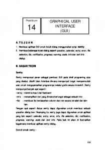
develop the necessary visualization tools as t simplifies in writing the programs, and it also provides .... Figure 3: Primer Application Window of the Sodar System.
www.ijird.com
December, 2013
Vol 2 Issue 12 (Special Issue)
ISSN 2278 – 0211 (Online) ISSN 2278 – 7631 (Print)
Design & Simulation of Graphical User Interface For SODAR System Using VC++ M. Bala Naga Bhushanamu Research Scholar, Department Of Systems Design, Andhra University, Visakhapatnam, A.P., India M. Hareesh Babu Research Scholar, Department Of Systems Design, Andhra University, Visakhapatnam, A.P., India M. Purnachandra Rao Professor and HOD, Department Of Systems Design, Andhra University, Visakhapatnam, A.P., India Abstract: Acoustic remote sensing is the Science and engineering of obtaining the spectral, spatial and temporal information about the state of the first few hundred meters of the atmosphere above ground without coming into physical contact with it. The development of the acoustic methods for atmosphere research essentially relies on achievement in theoretical and experimental investigation in sound propagation in the atmosphere. The principle of acoustic remote sensing of the atmosphere involves the Bragg scattering sound, Gilman was the first person to use the term SODAR from the acronym: Sound Detection And Ranging, has been used as a means to study the structure of the lower atmosphere. In this paper, an audible ‘beep’ is beamed up into the atmosphere and very faint echoes from features within the air itself are detected back at the ground. Microsoft VC++ is a powerful object – oriented application integrated development environment. This object – oriented program are rich in structure, methods and attributes. The object – oriented frame work provides an important enabling technology for reusing software components. In VC ++, these frameworks are supported by Microsoft Foundation Classes (MFC). The MFC is used to develop the necessary visualization tools as it simplifies in writing the programs and it also provides many High level features that can save considerable coding effort. In this paper, designed a powerful GUI function facilitate the time – height plots in such a way that the plot can be stored, retrieved and processed to eliminate unwanted fixed echo signal, which are of nonatmospheric origin for sodar system. This paper is divided into four different layers such as user layer, application layer, operating system layer, and Hardware / Physical layer. The user layer gives the input to the application layer by mouse click or inputs through GUI icons. The application layer performs the signal processing such as parameter determination and further communicates with the operating system layer. The operating system layer acts as a bridge between hardware layer and application layer. Finally the Hardware / Physical layer takes care of commands executions, which are given by operating system layer.
1. Introduction Microsoft VC++ is a powerful object – oriented application integrated development environment. Object – oriented programs are rich in structure: Methods and attributes belong to classes, objects are instances of classes, and interclass relationship entails, association, aggregation, inheritance, and call relationships. The object – oriented frameworks provide a important enabling technology for reusing software components. In VC++, these frameworks are supported by Microsoft Foundation Classes (MFC). The MFC is used to develop the necessary visualization tools as t simplifies in writing the programs, and it also provides many high-level features that can save considerable coding effort. Programs written under windows are generally event-driven, which means that every procedure is triggered as result of some event. Result of this mechanism, the program can update and redraw various controls simultaneously via the view class in the program, to achieve visualization capabilities. The CDC, one of the objects of MFC, provides member function for working with a device context, such as drawing tools, type-safe graphic device interface (GDI) object selection, working with colors and pallets. It also provides member function for getting and setting drawing attributes, mapping working with viewport, window extent, converting coordinates, working with region, clipping, drawing simple shapes. The powerful GUI function facilitate the time-height plots in such a way that the plot can be stored, retrieved and processed to eliminate unwanted fixed echo-signals, which are of non-atmospheric origin for the SODAR system. In order to present the data on the client area of a window, the GUI is critical in visual C++ programming language. The present system is divided into layer, and Hardware / physical layer. Figure 1 shows the block diagram of the layer structure of system-based applications. Each layer takes care of the commands received from respective layers. The user layer gives the input to the application layer by mouse click or inputs through GUI icons. The application layer performs the signal processing such as parameter determination and further communicates with the operating system layer. The
INTERNATIONAL JOURNAL OF INNOVATIVE RESEARCH & DEVELOPMENT
Page 155
www.ijird.com
December, 2013
Vol 2 Issue 12 (Special Issue)
operating system layer acts as a bridge between hardware layer and application layer. Finally the hardware / physical layer takes care of commands executions, which are given by operating system layer.
Figure 1: Block Diagram of Layer Structure for the PC-Based Application One of the important features of the Microsoft VC++ and MFC is the document view architecture. This architecture is versatile in programming the application and also offers distinct interfacing schemes such as single document interface (SDI) with a single view, SDI with multiple views, Multiple Document Interface (MDI) with multiple views. Among the three schemes, SDI with multiple views scheme is chosen for the present experiment. SDI is a document-centric application that works with one document at a time and only one type of document. 2. Design Features There are five parameters that need to be determined from the Doppler sodar echo-signal: display of echo-signal in the time domain, display of echo-signal FFT spectrum, display of time-height intensity plot in the form of the traditional facsimile record, display of vertical wind as a time-height plot, and display of horizontal wind as a time-height plot. Each parameter is displayed in a different client area in the designated five windows. The structural block diagram of the sodar echo-signal processing tool is presented in Figure 2. The processing of the Doppler sodar echo-signal starts with the digitization ion the sound card.
Figure 2: The Structural Block of Sodar Software The raw data is stored in a secondary memory using an exclusive worker thread of the program. The digital data of the each range gate is copied into a buffer and applied to the processing routines in a separate worker thread of the program. Threading is one of the important features of the Microsoft VC++ and it support multithreaded real-time application. A thread is a path of execution within process. The primary thread is supported to OS by the startup code in the form of function address. One can create these additional threads depending on the application demand, and all threads in MFC application are represented by CW in thread objects. The MFC distinguishes two types of threads: user interface threads and worker threads are commonly used to complete tasks, such as recalculation that do not require user input. The GUI for the present experiment is designed in a such a way that it consists of five switch-selectable data screens: data in time domain mode, data in frequency domain mode, intensity (facsimile) record, vertical wind, and horizontal wind display. The primary window of the GUI of the present Doppler sodar system in shown in Figure 3.
INTERNATIONAL JOURNAL OF INNOVATIVE RESEARCH & DEVELOPMENT
Page 156
www.ijird.com
December, 2013
Vol 2 Issue 12 (Special Issue)
Figure 3: Primer Application Window of the Sodar System When the user / operator clicks the button ‘File’ it shows a drop box which is shown in below Figure 4. The drop box shows three menu items, namely, Start, Stop, and Exit. By clicking the button ‘Start’, the system automatically takes the predefined sodar parameters and begins its operation. On its first window, by default, shows both transmitting and receiving signals in time domain mode. At any given time, if the user/ operator wants to switch over to observe the other windows or parameters, the tool provides another menu which is shown in the menu which is shown in the figure 5.
Figure 4: Pop-Up/ Drop Box of the Application of the Sodar
Figure 5: Pop-Up/ Drop Box of the Application of the Sodar
INTERNATIONAL JOURNAL OF INNOVATIVE RESEARCH & DEVELOPMENT
Page 157
www.ijird.com
December, 2013
Vol 2 Issue 12 (Special Issue)
Figure 6: Pop-Up/ Drop Box of the Application of the Sodar
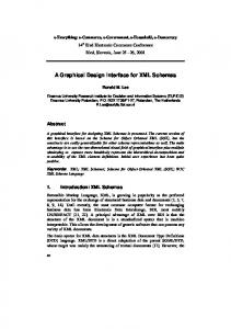
Figure 7: Pop-Up/ Drop Box Menu for Wind Record Likewise each and every syntax will incorporated in the Pop-up/drop box menu, which can leads different parameters to begin its operation. To shutdown the sodar system for any maintenance or for any other purpose, the button ‘stop’ has to be clicked on the file menu drop box. In order to store the current data plots, a few software routines are added to the program itself to create appropriate folder on secondary memory of the PC. Multithreading functionality is efficiently used in this design. In such a way that all data windows and other data saving tasks are accomplished simultaneously. Every time when sodar systems starts, a new folder is created on secondary memory with dates as folder name to save the various types of sodar data files. Further, four sub-folders are also created, namely ‘Raw_wave_Files’, ‘Facsimile’, ‘Vertical Wind’, and ‘Horizontal Wind’ within the main-folder, which was created earlier.
Figure 8: Window showing .Wav Files Saved With Date & Time
INTERNATIONAL JOURNAL OF INNOVATIVE RESEARCH & DEVELOPMENT
Page 158
www.ijird.com
December, 2013
Vol 2 Issue 12 (Special Issue)
Figure 9: Window showing .Bmp Files Saved With Date & Time
3. Conclusion Defining the parameters for sodar system to using object- oriented application like Microsoft VC++, will gives tremendous advantages. This object – oriented program are rich in structure, methods and attributes. This paper is divided into four different layers such as user layer, application layer, operating system layer, and Hardware / Physical layer. The user layer gives the input to the application layer by mouse click or inputs through GUI icons. The application layer performs the signal processing such as parameter determination and further communicates with the operating system layer. The operating system layer acts as a bridge between hardware layer and application layer. Finally the Hardware / Physical layer takes care of commands executions, which are given by operating system layer. Therefore designing of this software will also reduce the cost effect and hardware compellability and can use worldwide with Microsoft platform. 4. Acknowledgement The work has been carried out with the financial support by UGC, New Delhi through a major research project entitled “DEVELOPMENT OF PORTABLE DOPPLER SODAR SYSTEM FOR WIND FARM SITING APPLICATIONS”. 5. References 1. Abdullahi, M.M., Ali, N.B., and Ahmed, K.B.H., ‘Elapse time factor on induced vegetative moisture uptake in an unsaturated soil’. 2. http://en.wikipedia.org/wiki/SODAR. 3. http://www.sodar.com/about_sodar.htm. 4. "What's New in Visual Basic 2010". Microsoft. 2010. Retrieved 1 August 2010. 5. http://www.microsoft.com/en-download/details.aspx?id=5555
INTERNATIONAL JOURNAL OF INNOVATIVE RESEARCH & DEVELOPMENT
Page 159