Hindawi Publishing Corporation Mathematical Problems in Engineering Volume 2015, Article ID 985837, 13 pages http://dx.doi.org/10.1155/2015/985837
Research Article An Open Modular Architecture Controller Based Online Chatter Suppression System for CNC Milling Zhenyu Han,1 Hongyu Jin,1 Maoyue Li,2 and Hongya Fu1 1
School of Mechatronics Engineering, Harbin Institute of Technology, Harbin 150006, China Mechanical and Power Engineering College, Harbin University of Science and Technology, Harbin 150080, China
2
Correspondence should be addressed to Hongya Fu;
[email protected] Received 23 March 2015; Accepted 7 July 2015 Academic Editor: Lihui Wang Copyright © 2015 Zhenyu Han et al. This is an open access article distributed under the Creative Commons Attribution License, which permits unrestricted use, distribution, and reproduction in any medium, provided the original work is properly cited. In milling processes, chatter is a kind of sudden relative vibration appearing between the cutter and the workpiece, which results in poor part quality, accelerated tool wear, and shortened spindle life. In this paper, an open modular architecture controller (OMAC) of machine tool which integrates the algorithms including chatter recognition, compensation command generation, and execution is proposed with the aim of providing an integrated solution for milling chatter suppression in CNC kernel. To effectively identify chatter, experiments are designed to determine the optimal installation place of accelerometer and then triaxial cutting forces and acceleration signals are compared to see which are more sensitive to chatter onset. In terms of data processing, 16 sampling points in time domain are chosen to perform online fast Fourier transform (FFT) in consideration of signal effectiveness and computational efficiency. To implement real-time chatter suppression in CNC kernel, a simplified dynamic model of milling system is used to obtain the relationship between chatter frequency and spindle speed. Finally, an adaptive control module which completes force signal extraction and processing by FFT and has the ability to modify related cutting parameters is designed to interact with other modules in OMAC where data acquisition thread and interpolation thread are synchronized. The proposed system is experimentally validated.
1. Introduction Chatter has been a limitation in terms of productivity and part quality in metal removal processes for the last sixty years. Regarding the related research, chatter has several negative effects: poor surface quality, unacceptable inaccuracy, excessive noise, disproportionate tool wear, waste of energy, and so forth [1, 2]. For these reasons, chatter avoidance or suppression is a topic of enormous interest and it is necessary to monitor, identify, and suppress chatter during metal machining processes. Generally, methods for chatter avoidance can be divided into two groups, out-of-process and in-process methods. Out-of-process strategies are focused on predicting, estimating, identifying, or enlarging the stability lobe diagrams (SLD) through machining process modeling, analyticalexperimental methods, improving the design of machine tool to change its performance against vibration, or adding extra devices (e.g., dampers) that can absorb extra energy [3–5].
The idea is to select optimal cutting parameters by seeking stable regions between lobs of stability chart with some predefined criteria [6, 7]. Urbikain et al. [8] proposed two methods of signal frequency model and Chebyshev polynomials to predict chatter in big horizontal lathes. Recently, they presented a technique based on the MATLAB dde23 routine for stability and time simulation purposes with a competitive computation time for large time delays. The proposed dde23 algorithm is more efficient and can be used to reproduce the vibrational behavior of turning systems [9]. Quintana et al. [10, 11] proposed an experimental method to identify real SLD using the inclined plane machining. Khachan and Ismail [12] developed a graphical approach for time-domain simulation of chatter in multiaxis milling. Shamoto et al. [13] presented a method to machine flexible plates using simultaneous double-sided milling. This technique solved the difficulties of flexible plate milling but causes regenerative chatter vibration. To suppress chatter, the authors proposed rotating the two milling cutters at different speeds to cancel
2 the regenerative effects on both plate sides. Ganguli et al. [14] proposed the use of an active damping system, based on an accelerometer to measure the machine tool vibrations and an electromagnetic proof-mass damper, also called an active mass damper (AMD), to enhance the stability limits of the system. However, in some cases of complex machining (e.g., where there are more than three axes), the SLD of system involving cutting tool, machine tool, and workpiece is continuously changing; thus it is difficult to predict chatter in advance and schedule correct parameters [15]. And changing design of machine tool or adding extra devices to absorb extra energy is not easy, even infeasible for operators to implement, which is mostly performed by machine tool manufacturers. In terms of in-process strategies, chatter vibration must be recognized ahead of chatter elimination by monitoring a certain signal such as vibration and sound power, with different sensors as soon as it arises. Aiming to reduce the negative effects of chatter as much as possible, chatter recognition should be completed timely with minimum relevant and useful signals and efficient signal processing algorithms when chatter just begins and is not completely developed. Rahman and Ito [16] proposed a method to determine the onset of chatter through the in-process measurement of the horizontal deflection of the workpiece. Tansel et al. [17] presented the use of index-based reasoning for chatter detection through the torque signal data of rotary dynamometers during end milling. Yang et al. [18] proposed a method of chatter recognition in boring operations by monitoring spindle motor current. After the chatter is identified, the next critical step is to suppress it. In [19], the development of chatter suppression has been reviewed in detail. Munoa et al. [20] proposed an active suppression method for structural chatter vibrations using machine drives and accelerometers. Olgac and Hosek [21] presented an approach to eliminate chatter based on root locus plot analysis and using a delayed resonator for vibration suppression. Chiou et al. [22] proposed an algorithm to control chatter by changing the response function of the structure and its modal properties using active electrostatic and piezoelectric spindle bearing support. Nevertheless, these solutions have to add complicated and expensive actuators which are computer controlled to absorb, balance, or supply energy, thus making a great change to the current machining system which is inevitable. By contrast, varying cutting parameters in process to ensure a stable process is a more economical and flexible way. The well-known technique to suppress regenerative machine tool vibration is varying the spindle speed or feed rate. Smith and Tlusty [23] presented a chatter recognition and control system to eliminate chatter by automatic spindle speed regulation in the early years. In that implementation, the cutting sound is sampled using a microphone, a PC, and a Digital Signal Processing board. Kim et al. [24] developed a separate embedded device with DSP to determine the occurrence of chatter by processing acceleration signals and the compensation command transmitted from the RS232 module to the Bluetooth module, which could communicate with machine tool controller to make feed rate variation.
Mathematical Problems in Engineering In the above publications, the signal treatment and chatter recognition are conducted in a separate computer, in parallel with the CNC kernel. The commands to compensate chatter have to be transferred from the separate device to machine tool controller by certain communication interface, and the real-time performance of communication is often limited by bottleneck of baud rate. Furthermore, given that the compensation command could be received by CNC in realtime manner, it is difficult to interrupt the running cycle of NC kernel of traditional “closed” CNC in a real-time basis. Therefore, the performance of in-process chatter suppression would be discounted. It seems that the ideal solution of in-process chatter suppression is to integrate the algorithms including chatter recognition and compensate command generation into the CNC kernel, which constitutes a completely integrated system of chatter suppression. But many challenges which must be overcome for this solution include (1) the CNC kernel that should be an open architecture to facilitate the integration of chatter recognition and ensure the real-time modulation of interpolation or cutting parameters; (2) sensor signals that should be optimally selected to minimize the load of signal processing algorithm; (3) signal processing algorithms that should be computationally efficient to enhance the real-time performance. Different from the above in-process strategies which must have extra DSP or PC, in this research, an open modular architecture controller (OMAC) of machine tool is proposed for integration of chatter suppression. Data acquisition and online parameter modulation are executed synchronously with modules (e.g., axis group) in OMAC of machine tool. When chatter occurs, cutting parameters of machine tool could be adjusted in real-time manner to ensure machining stability, which provides a chatter suppression solution in CNC kernel layer. The rest of this paper is organized as follows. In Section 2 of this paper, the most sensitive signals among force and acceleration sensors during monitoring processes are identified and extracted by comparative analysis in both time domain and frequency domain. Then an algorithm of online chatter suppression based on milling dynamics model is provided in Section 3, which builds the relationship between chatter frequency and spindle speed through the single degree of freedom (SDOF) model of milling system. Lastly, the realization of online chatter suppression in OMAC and the experimental verification in aluminum alloy milling are presented.
2. Identification and Extraction of Chatter Signal 2.1. Identification of Sensitive Monitoring Signal. To realize online chatter suppression, it is very important to choose the most sensitive chatter signal for real-time control. The process of signal acquisition should meet the following conditions: high signal-to-noise ratio, signal acquisition with high sensitivity, and convenient installation and operation for sensors. Many sensors, such as dynamometer, accelerometer, and microphone, have the ability of chatter detection. To
Mathematical Problems in Engineering
3
Driver
OMAC
SERCANS
Spindle A
Data acquisition
Amplifier Workpiece B Dynamometer
C Motor
Table
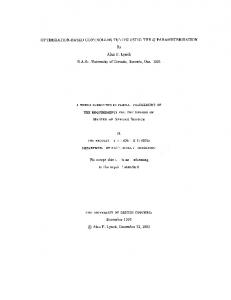
Figure 1: Schematic diagram of the experimental machining system.
100 mm 24 mm
17 mm
(a)
(b)
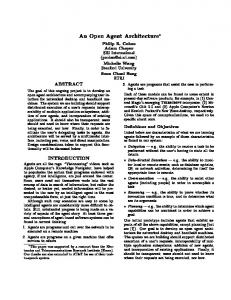
Figure 2: (a) Machine tool with OMAC and (b) uncut workpiece.
satisfy the above conditions, this paper extracts the effective information in machining trials using the piezoelectric dynamometer and accelerometer. The force and acceleration signals can be acquired and processed in real time through OMAC (as shown in Figure 1). Figure 2 shows the experimental machine tool with OMAC and the uncut aluminum alloy workpiece. There are two issues concerning this experiment: (1) the optimal arrangement of accelerometer would be determined in order to eliminate the interference of unconcerned messages from chatter signal (in Figure 1, three installation positions of A, B, and C are preset for comparison); (2) the sensitivity characteristic of signals between dynamometer and accelerometer would be compared under the same cutting condition. Based on the SLD in [23], three groups of cutting parameters (as shown in Table 1) are selected to obtain different cutting states. According to the experimental results, the amplitude of acceleration signal in position A is quite small, and the changes in the amplitude are not correlated with shape feature of workpiece. It may be caused by the vibration from spindle itself. By contrast, the amplitude of signals in positions B and C has a similar trend in terms of cutting depth. Furthermore, the amplitude in position B is larger than that in position C, which could reflect the characteristics of chatter signal and workpiece better. Therefore, position B is fixed as the location for accelerometer to mount.
Table 1: Parameter setting of experimental identification. Tool: a ball-end cutter with two flutes; ball radius = 3 mm. Group 1 2 3
Spindle speed 𝑛/(r/min)
Feed rate V/(mm/min)
Radial depth of cut 𝑎/mm
3000 4500 6000
300 400 500
0.6 0.6 0.6
The sampled raw signals of force and acceleration (in position B) and corresponding frequency analysis result are shown in Figures 3 and 4, where Figure 3 shows the 3D resultant force of 𝐹𝑥 , 𝐹𝑦 , and 𝐹𝑧 and acceleration signals in time and frequency domain among three groups of experiments and Figure 4 shows triaxial force and acceleration signals in time and frequency domain in experimental Group 2. Through analyzing data, some results could be summarized as follows: (1) In Figure 3, it could be discovered that the trend of cutting force signals could clearly reflect the geometry of the workpiece than acceleration signals. In experimental Group 1, the milling process was basically stable in the whole process. But when the spindle speed rose to 4500 rpm, the chatter vibration happened in the end stage of Group 2. It is mainly
300
200
200
Force (N)
300
100
100
0 0
20
40 Time (s)
0
60
0
50
100 50 0
200
200
0
50
100
150
Force (N)
4
Force (N)
300
0
100 0
200
0
10
200 0 20 Time (s)
30
30 20
10 100
150
300
10 5 100
150
200
1000
500
0
0
Frequency (Hz) (j) The spectrum of resultant cutting force (Group 3)
100
150
200
200
100 0
200
(h) The spectrum of resultant acceleration (Group 2)
Acceleration (m/s2 )
40
50
15
50
60
(f) The spectrum of resultant cutting force (Group 2) 400
0
50
0
10 20 Time (s)
Frequency (Hz)
(g) The time domain of resultant acceleration (Group 2)
0
0
20
0
40 Time (s)
Frequency (Hz)
(i) The time domain of resultant cutting force (Group 3)
Acceleration (m/s2 )
10
20
100 0
30
Force (N)
400
20 Time (s)
(e) The time domain of resultant cutting force (Group 2)
Acceleration (m/s2 )
600
0
0
(c) The time domain of resultant acceleration (Group 1)
300
(d) The spectrum of resultant acceleration (Group 1)
Acceleration (m/s2 )
200
(b) The spectrum of resultant cutting force (Group 1)
Frequency (Hz)
Force (N)
150
200 150
6
2
0
100
250
Frequency (Hz)
(a) The time domain of resultant cutting force (Group 1)
Acceleration (m/s2 )
Acceleration (m/s2 )
Mathematical Problems in Engineering
Force (N)
4
10 20 Time (s)
(k) The time domain of resultant acceleration (Group 3)
20 15 10 5 0
0
50
100
150
200
Frequency (Hz) (l) The spectrum of resultant acceleration (Group 3)
Figure 3: Force and acceleration signals in time and frequency domain.
caused by the change of cutting depth in continuous cutting process. Moreover, chatter frequency which is different from tooth passing frequency appeared in experimental Group 3 when the spindle speed was 6000 rpm. (2) In Figure 4, it could be found that the feed (𝑋) cutting force is more sensitive than radial (𝑌) cutting force and axial (𝑍) cutting force in low radial immersion milling, and it reaches the amplitude peak when chatter occurs. However, in time domain of acceleration, the amplitudes of triaxial acceleration signals
fluctuate enormously. There are several similarities in terms of experimental Group 1 and Group 3. (3) In frequency diagram, the spectrum of feed (𝑋) cutting force could more clearly reflect the tooth passing frequency (𝑓𝑡 = 150 Hz corresponding to spindle speed of 4500 rpm) and the less stable chatter frequency (𝑓𝑐1 = 𝑓𝑡 /3, 𝑓𝑐2 = 2𝑓𝑡 /3, . . .) in the low frequency region, compared with acceleration under the same cutting condition. To sum up, feed cutting force signals in side milling could reflect the processing characteristics clearly. It is difficult to
Mathematical Problems in Engineering
5
0
100 0
10 20 Time (s)
0
30
0 −200 10 20 Time (s)
400 200 0 −200 −400
30
(d) 𝑋 acceleration in time domain
Force (N)
Force (N)
50
100
150
150
−500
200
20
100 0
50
100
150
200
Frequency (Hz) (j) The spectrum of 𝑋 acceleration
0
100
150
50
100
150
200
(i) The spectrum of 𝑍 cutting force
Acceleration (m/s2 ) 50
30
Frequency (Hz)
10
0
10 20 Time (s)
10 0
200
20
0
0
(f) 𝑍 acceleration in time domain
(h) The spectrum of 𝑌 cutting force
Acceleration (m/s2 )
Acceleration (m/s2 )
10
100
30
Frequency (Hz)
20
50
10 20 Time (s)
30
0
30
0
200
(g) The spectrum of 𝑋 cutting force
0
10 20 Time (s)
500
300
Frequency (Hz)
0
0
(e) 𝑌 acceleration in time domain
100
50
0
(c) 𝑍 cutting force in time domain
Acceleration (m/s2 )
200
0
−40 −60
30
(b) 𝑌 cutting force in time domain
Acceleration (m/s2 )
400
0
20
0 −20
Time (s)
(a) 𝑋 cutting force in time domain
0
10
20
Force (N)
0
Acceleration (m/s2 )
200
Force (N)
100
−400
40
300 Force (N)
Force (N)
200
200
Frequency (Hz) (k) The spectrum of 𝑌 acceleration
20 15 10 5 0
0
50
100
150
200
Frequency (Hz) (l) The spectrum of 𝑍 acceleration
Figure 4: Triaxial force and acceleration signals in time and frequency domain (in experimental Group 2).
judge whether chatter occurs or not from time-domain signals. And in terms of frequency-domain signals, there must exist nonstable cutting once cutting frequency is different from the main frequency. Thus, the frequency characteristics of feed force signal are determined for chatter identification in this research. 2.2. Extraction of Effective Chatter Signals. Based on the above analysis, to observe dynamic characteristics of machining process, analysis of frequency-domain signals should be conducted. At present, the frequency analysis methods mainly include fast Fourier transform (FFT), short-time Fourier transform (STFT), and wavelet transform (WT). Generally, it is difficult to choose suitable basis functions for STFT and WT, and the calculation speed of them is far slower than FFT. Furthermore, in this research, to carry out online
chatter identification and suppression in CNC kernel, several requirements should be met: (i) real-time sampling data processing and analysis; (ii) coordination between signal processing and interpolation cycle of CNC system; (iii) a simple control algorithm to reduce the load on controller. Through the above comprehensive analysis, FFT is used to ensure real-time signal processing and chatter identification in this paper, due to its ability of rapid data processing and relatively simple algorithm. To illustrate the validity of this identification method, a section of feed force signals in time domain (extracted from Figure 4(a)) is extracted and analyzed, as shown in Figure 5.
6
Mathematical Problems in Engineering
Feed cutting force (N)
150
is realized by Application Programming Interface of system platform. When the CNC system is started, human-machine module automatically loaded task coordinator module. And then task coordinator module could realize the function of information exchange by coordinating other modules in the proposed OMAC.
100
50
0 5000 5100 5200 5300 5400 5500 5600 5700 5800 5900 6000 Sampling sequence
Figure 5: Extraction of cutting force data.
The sampled data in Figure 5 could be separated into three sections, the normal milling section (no chatter, such as 5400–5500), transition stage (5700–5800), and chatter section (5800–6000). Compared with FFT among different numbers of sampling points, FFT with 16 sampling points is the least amount of sampling points which can show frequency characteristics in this research, and it has the same operation cycle in terms of interpolation process to realize synchronous coordination in this OMAC of machine tool. Figure 6 shows the frequency-domain characteristics between 100 sampling signals and 16 sampling signals from each section; it could be found that relative frequency and spectral amplitudes are very similar under the same milling condition even though they have different amount of sampling data. Therefore, chatter in milling can be identified online using 16 sampling signals to ensure the real-time acquisition and control of machine tool as well in this research.
3. Implementation Techniques of Online Chatter Suppression 3.1. The Modular Design of OMAC. In OMAC of machine tool, modular architecture has been adopted in the designed controller, which could realize real-time signal processing and online chatter suppression due to its openness. In this paper, the structure of OMAC is presented in Figure 7. As shown in Figure 7, the proposed OMAC is divided into several function modules, and every module is an independent component. Among all the modules, adaptive control module is the key to realize online chatter suppression in OMAC, which completes force signal extraction and processing by FFT, and has the ability to modify related cutting parameters based on milling dynamic model. Task coordinator module is another important module, which is responsible for real-time scheduling and coordination between each module in OMAC. In such integrated system, information exchange among modules is of critical importance, which
3.2. The Model for Online Chatter Suppression. Chatter is usually caused by the interaction of the chip removal process and the structure of machine tool. Specifically, chatter is a highly complex phenomenon due to the diversity of dynamic system. At present, many dynamic models, such as multidegree of freedom (MDOF) model, have been studied by some researchers, which include a large number of complex parameters. To reduce the load of OMAC and to ensure real-time modulation as much as possible, a SDOF dynamic model of milling which is described by Tlusty and Altintas [25, 26] is used to achieve online chatter suppression in this paper. In Figure 8, ℎ0 is the nominal uncut chip thickness and 𝜀 is the phase difference between two consecutive cuts. Assuming that cutting force 𝐹 is proportional to instantaneous uncut chip thickness, then the process of chatter occurrence can be simplified by a control block diagram, as shown in Figure 9. There are two closed loops in Figure 9, where ℎ𝑛 is instantaneous uncut chip thickness; 𝐺𝑐 represents the cutting process; 𝐹(𝑠) is the resultant cutting force; 𝑋(𝑠) is the current position of cutting surface; and 𝜏 is the time delay between two continuous cutting processes. The dynamic characteristics of machining process are expressed by global transfer function 𝐺𝑚 , which is composed of the sum of transfer functions in each mode 𝐺𝑖 and orientated by the directional factor 𝜇𝑖 , as shown in 𝑛
𝐺𝑚 = ∑𝜇𝑖 𝐺𝑖 .
(1)
𝑖=1
Cutting process 𝐺𝑐 could be expressed as the product of static cutting stiffness 𝐾𝑐 and radial depth of cut 𝑏: 𝐺𝑐 = 𝐾𝑐 𝑏.
(2)
The transfer function of this control system (in Figure 9) is given by 𝐺𝑐 𝐺𝑚 / (1 + 𝐺𝑐 𝐺𝑚 ) 𝑋 (𝑠) = ℎ0 (𝑠) 1 − 𝐺𝑐 𝐺𝑚 / (1 + 𝐺𝑐 𝐺𝑚 ) exp (−𝜏𝑠) 𝐺𝑐 𝐺𝑚 = . 1 + 𝐺𝑐 𝐺𝑚 − 𝐺𝑐 𝐺𝑚 exp (−𝜏𝑠)
(3)
The stability limit is calculated using the Nyquist criterion, which establishes that the transfer function’s gain on an open loop must have critical value −1 for the system to be at the stability limit: 𝐺𝑐 𝐺𝑚 (1 − exp (−𝜏𝑠)) = − 1.
(4)
7
90
90
80
80
70
70
60
60
Feed force (N)
Feed force (N)
Mathematical Problems in Engineering
50 40 30
50 40 30
20
20
10
10
0
0
20
40
60
80 100 120 Frequency (Hz)
140
160
180
0
200
0
20
(a) Data between 5401 and 5500
40
60
80 100 120 Frequency (Hz)
140
160
180
140
160
180
140
160
180
(b) Data between 5450 and 5465
120
150
80
Feed force (N)
Feed force (N)
100
60 40
100
50
20 0
0
20
40
60
80 100 120 Frequency (Hz)
140
160
180
0
200
0
20
(c) Data between 5701 and 5800
160
160
140
140
80 100 120 Frequency (Hz)
120
120
Feed force (N)
Feed force (N)
60
(d) Data between 5784 and 5799
180
100 80 60
100 80 60 40
40
20
20 0
40
0
20
40
60
80 100 120 Frequency (Hz)
140
(e) Data between 5801 and 6000
160
180
200
0
0
20
40
60
80 100 120 Frequency (Hz)
(f) Data between 5900 and 5915
Figure 6: Spectrum for three sections of sampling data.
8
Mathematical Problems in Engineering
Task generator module
hn
h0
Human-machine module
+
+
+
−
F(s)
Gc Cutting process
Gm
X(s)
Machine response
PLC module Task coordinator module
Moving axis Axis-group module
Adaptive control module
Inner modulation
Spindle Axis-group module
Outer modulation
exp(−𝜏s)
Figure 9: Control loop diagram of machining system [28]. Spindle Axis module
Moving axis Axis module
where 𝑓𝑡 is the tooth passing frequency, 𝑓𝑐 is the chatter frequency, 𝑛𝑠 is the spindle speed, 𝑍 is the number of cutter tooth, 𝑘 is positive integer, and 𝑢 is a parameter in the range of 0∼1. Since the stability limit of radial depth of cut must be a positive real value, the term of the denominator in (5) must be real negative value:
System platform PC + Windows + RTX + SoftSERCANS + PCI1710
Figure 7: Structure of OMAC.
𝐺𝑚 (1 − exp (−𝑗𝜔𝜏)) = 2 Re { 𝐺𝑚 (𝑗𝜔)neg } .
Force k
When this expression is substituted into (5), the threshold radial depth of cut is obtained:
c
𝑏=−
Previous cutting surface
Chip
Tool
Current cutting surface
Figure 8: SDOF model of the machine tools’ processing system [27].
From (2) and (4), radial depth of cut 𝑏 in Fourier domain is obtained:
(5)
where 𝜔 is the angular chatter frequency. Phase difference 𝜀 will occur due to the delay in successive cutting processes, which could be determined through the relationship between tooth passing frequency and chatter frequency. Assuming the number of chatter wave between previous and current cutting process is (𝑘 + 𝑢), therefore, phase difference could be expressed by 2𝜋𝑢: 𝑓𝑐 𝑓𝑐 𝑛𝑠 𝑍 = = , 60 𝑘 + 𝑢 𝑘 + 𝜀/2𝜋
(8)
(6)
Re (𝐺𝑚 (𝑗𝜔)) . Im (𝐺𝑚 (𝑗𝜔))
(9)
Therefore, the stable spindle speed selection algorithm consumes chatter energy through the best vibration phase 𝜀 → 2𝜋, and this leads to a useful equation for regulation or selection of stable spindle speed: 𝑛𝑠 =
−1 , 𝐾𝑐 𝐺𝑚 (𝑗𝜔) (1 − exp (−𝑗𝜔𝜏))
𝑓𝑡 =
. 2𝐾𝑐 Re { 𝐺𝑚 (𝑗𝜔)neg }
𝜀 = 2𝜋 − 2tan−1
𝜀
−1 𝑏= 𝐾𝑐 𝐺𝑚 (𝑠) (1 − exp (−𝜏𝑠)) 𝑠=𝑗𝜔
1
If it is assumed that Re{𝐺𝑚 (𝑗𝜔)} → 0, then an ideal scenario is obtained with an infinite width of cut. This assumes that phase shift between waves is zero:
h0
=
(7)
60𝑓𝑐 . (𝑘 + 1) 𝑍
(10)
The spindle speed of machine tool is not unique because 𝑘 is a variable parameter. In this application, the spindle speed nearest to the current speed is advised, which could not only suppress the chatter but also guarantee the preset cutting speed as much as possible. 3.3. Scheme of Spindle Speed Variation to Suppress Chatter. The strategy of how to implement in-process chatter suppression is presented in this section. The flow chart of collection, processing, and storage of sampling data in adaptive control module is indicated in Figure 10. As soon as real-time main thread is started in the task coordinator module, cutting force data is collected from A/D channel. Meanwhile, collected data is filtered and processed in the adaptive control module, and spindle adjusting rate is calculated intelligently based on FFT results.
Mathematical Problems in Engineering
9
Start
Acquisition of force signals in real time
Intelligent control
No
Current spindle speed in shared memory
Yes FFT
Chatter occurrence
No
Keep the current spindle speed
Yes Calculation of optimal spindle speed by (9)
New spindle speed in shared memory
End
Figure 10: Process of spindle speed update.
The detail of processing algorithm in OMAC is shown in Figure 11. Two timers for data acquisition thread and interpolation thread are designed to realize synchronous control in task coordinator module of OMAC. In data acquisition thread, feed cutting force signals are extracted, and frequency characteristics of 16 sampling points in each collection are analyzed. If chatter happens, updated spindle speed which is suitable for current machining situation will deposit in shared memory to suppress chatter by online signal processing and execution. Through interpolation thread, structure in axisgroup module can update the information of spindle speed which deposited in shared memory and trigger the real-time function in axis module. Consequently, cycle control signals could be exchanged smoothly and compensation command can be generated to modulate the spindle of machine tool in real time.
4. Experimental Results To verify the effectiveness and feasibility of the proposed strategy in OMAC, a contrast experiment is performed on a vertical milling machine. The material of workpiece is aluminum alloy (as shown in Figure 2(b)), and the diameter of cutting tool is 6 mm. The cutting parameters in Group 2 of
Table 1 are selected, of which spindle speed is 4500 rpm, feed rate is 400 mm/min, and radial depth of cut is 0.6 mm. The feed force signals, feed rate and spindle speed of machine tool, and online process spectrum waveform are shown in Figure 12. It could be seen that the amplitude of feed cutting force is reduced by 33% compared with the former signal acquisition experiments (such as Figure 5) due to online control, and the whole cutting process has become more stable. In addition, feed rate of machine tool is set fixed in the whole cutting process and just fluctuating in a small range around setting value. As the cutting depth increases gradually and reaches the cutting stability limit, spindle speed was automatically adjusted to about 2000 rpm based on designed algorithm at the time of 20 seconds. Furthermore, from online process spectrum (as shown in Figure 12(d): a 3D figure, in which 𝑥-axis is serial number, 𝑦-axis is frequency, and 𝑧-axis is amplitude), the dominant frequency is 150 Hz before the calculation of 150th times, which is equal to tooth passing frequency of two edged cutters at this spindle speed. However, calculating online process spectrum from the 150th time to the end, the corresponding frequency at the peak trends to 100 Hz, which definitely illustrates that cutting process is transited to a stable state by updating spindle speed in real time.
10
Mathematical Problems in Engineering
Start Communication initialization between PLC processes
Start real-time main thread
Task coordinator module initialization
SERCANS initialization Start speed and position control mode
Automatic running thread startup
Omitting other processes
No
Manual thread start
Yes Open data acquisition timer 1
Open interpolation timer 2
Data filtering processing
Double ended queue is empty
Write real-time force signals
Termination of the main thread
Yes
No
Shared memory 1
Double ended queue eject motion segment
Read real-time force signals Adaptive control module
Interpolation of FSM by axis-group module
Omitting other processes
Write real-time spindle speed Shared memory 2
The state of FSM is running
Read new spindle speed
No
FSM is run_done
Yes
Update the spindle speed
Spindle driver
End
Figure 11: Online chatter suppression process.
Figure 13 shows the enlargement for workpiece surface before and after online chatter suppression, and it clearly shows that vibration marks on workpiece surface are reduced obviously. Surface roughness of workpiece is detected by aspheric surface measurement system (Form Talysurf PGI 1240). From Figure 14(a), the average surface roughness in steady cutting region is 2 𝜇m, while that in chatter region is 5 𝜇m. After online chatter suppression (as shown in Figure 14(b)), surface roughness in most of the cutting region is 2 𝜇m, in addition to the onset of chatter. Generally, surface quality of workpiece is improved effectively by the technique of online chatter suppression. But, in the measuring position
of 912 to 914 mm, surface roughness of workpiece is larger than the average value. The reason is that machining section has undergone a period of chatter before online suppression. So the future research will focus on how to forecast chatter as soon as possible in the whole process through OMAC of machine tool.
5. Conclusions An online chatter suppression system which is integrated into the CNC kernel is presented and experimentally validated. The signal treatment, chatter recognition, and compensation
Mathematical Problems in Engineering
11
200
600 500 Feed rate (mm/min)
Force (N)
150 100 50 0 −50
400 300 200 100
0
5
10
15 Time (s)
20
25
0
30
5
0
10
(a) Feed cutting force
20
25
30
(b) Feed rate
6000
1400 1200 Amplitude (N)
5000 4000 3000
1000 800 600 400 200
2000 1000 0
0
5
10
15 Time (s)
20
25
30
(c) Spindle speed
300 0 200
mber
Serial nu
Spindle speed (mm/min)
15 Time (s)
100 0 0
20
40
60
80 100 120 140 160 180 200 Frequency (Hz)
(d) Online process spectrum waveform
Figure 12: Variation of cutting parameters.
Accelerometer
Dynamometer (a) Before chatter suppression
(b) After chatter suppression
Figure 13: Enlargement figure for workpiece surface.
command generation algorithms work as an adaptive module in the proposed OMAC, which provides an integrated solution for online chatter suppression as well as a uniform machine tool-operator environment. Feed cutting force signals are determined to be relevant and useful signals for chatter recognition in side milling. Processing algorithms and a single degree of freedom model are specialized to facilitate chatter suppression in CNC kernel. The proposed system is
shown to be capable of detecting chatter and reducing its negative effect before chatter is fully developed. The main drawback of the proposed chatter suppression system is that it waits for the problem to appear and then takes action. Future work will include making predictive judgment of chatter before its onset, evaluating the system performance in terms of computational cost and memory usage, and extending the application to high speed machining.
10 8 6 4 2 0 −2 −4 −6
10 8 6 4 2 0 −2 −4 −6 882 884 886 888 890 892 894 896 898 900 902 904 906 908 910 912 914 916 918 920 922
10 8 6 4 2 0 −2 −4 −6 870 872 874 876 878 880 882 884 886 888 890 892 894 896 898 900 902 904 906 908 910
10 8 6 4 2 0 −2 −4 −6
Measuring position (mm)
Measuring position (mm)
(a) Before chatter suppression
Roughness (𝜇m)
Mathematical Problems in Engineering
Roughness (𝜇m)
12
(b) After chatter suppression
Figure 14: Detection of surface roughness.
Conflict of Interests The authors declare that there is no conflict of interests regarding the publication of this paper.
Acknowledgment
[10]
[11]
This study is financially supported by National Science and Technology Major Projects of China (Grant no. 2013ZX04013-011).
References [1] X. Zhou, D. Zhang, M. Luo, and B. Wu, “Toolpath dependent chatter suppression in multi-axis milling of hollow fan blades with ball-end cutter,” The International Journal of Advanced Manufacturing Technology, vol. 72, no. 5-8, pp. 643–651, 2014. [2] S. Tangjitsitcharoen and N. Pongsathornwiwat, “Development of chatter detection in milling processes,” The International Journal of Advanced Manufacturing Technology, vol. 65, no. 58, pp. 919–927, 2013. [3] E. Al-Regib and J. Ni, “Chatter detection in machining using nonlinear energy operator,” Journal of Dynamic Systems, Measurement and Control, vol. 132, no. 3, pp. 1–4, 2010. [4] A. J. Tang and Z. Q. Liu, “Three-dimensional stability lobe and maximum material removal rate in end milling of thinwalled plate,” International Journal of Advanced Manufacturing Technology, vol. 43, no. 1-2, pp. 33–39, 2009. [5] K. C. Cha, N. Wang, and J. Y. Liao, “Dynamics and cutting stability of the dynamically loaded worktable subjected to simply supported conditions,” International Journal of Advanced Manufacturing Technology, vol. 71, no. 1–4, pp. 605–620, 2014. [6] A. R. Yusoff, S. Turner, C. M. Taylor, and N. D. Sims, “The role of tool geometry in process damped milling,” International Journal of Advanced Manufacturing Technology, vol. 50, no. 9–12, pp. 883–895, 2010. [7] M. Zatarain, I. Bediaga, J. Mu˜noa, and R. Lizarralde, “Stability of milling processes with continuous spindle speed variation: analysis in the frequency and time domains, and experimental correlation,” CIRP Annals—Manufacturing Technology, vol. 57, no. 1, pp. 379–384, 2008. [8] G. Urbikain, F.-J. Campa, J.-J. Zulaika, L.-N. L´opez de Lacalle, M.-A. Alonso, and V. Collado, “Preventing chatter vibrations in heavy-duty turning operations in large horizontal lathes,” Journal of Sound and Vibration, vol. 340, pp. 317–330, 2015. [9] G. Urbikain, D. Olvera, L. N. L. de Lacalle, and A. El´ıas-Z´un˜ iga, “Stability and vibrational behaviour in turning processes with
[12]
[13]
[14]
[15]
[16]
[17]
[18]
[19]
[20]
low rotational speeds,” The International Journal of Advanced Manufacturing Technology, 2015. G. Quintana, J. Ciurana, I. Ferrer, and C. A. Rodr´ıguez, “Sound mapping for identification of stability lobe diagrams in milling processes,” International Journal of Machine Tools and Manufacture, vol. 49, no. 3-4, pp. 203–211, 2009. G. Quintana, F. J. Campa, J. Ciurana, and L. N. L. De Lacalle, “Productivity improvement through chatter-free milling in workshops,” Proceedings of the Institution of Mechanical Engineers, Part B: Journal of Engineering Manufacture, vol. 225, no. 7, pp. 1163–1174, 2011. S. Khachan and F. Ismail, “Machining chatter simulation in multi-axis milling using graphical method,” International Journal of Machine Tools and Manufacture, vol. 49, no. 2, pp. 163–170, 2009. E. Shamoto, T. Mori, K. Nishimura, T. Hiramatsu, and Y. Kurata, “Suppression of regenerative chatter vibration in simultaneous double-sided milling of flexible plates by speed difference,” CIRP Annals—Manufacturing Technology, vol. 59, no. 1, pp. 387– 390, 2010. A. Ganguli, A. Deraemaeker, and A. Preumont, “Regenerative chatter reduction by active damping control,” Journal of Sound and Vibration, vol. 300, no. 3–5, pp. 847–862, 2007. E. Soliman and F. Ismail, “Chatter suppression by adaptive speed modulation,” International Journal of Machine Tools and Manufacture, vol. 37, no. 3, pp. 355–369, 1997. M. Rahman and Y. Ito, “Detection of the onset of chatter vibration,” Journal of Sound and Vibration, vol. 109, no. 2, pp. 193–205, 1986. I. N. Tansel, M. Li, M. Demetgul, K. Bickraj, B. Kaya, and B. Ozcelik, “Detecting chatter and estimating wear from the torque of end milling signals by using Index Based Reasoner (IBR),” International Journal of Advanced Manufacturing Technology, vol. 58, no. 1–4, pp. 109–118, 2012. Z. G. Yang, H. Q. Liu, B. Li, and X. L. Liu, “Recognition of chatter in boring operations using spindle motor current,” in Proceedings of the International Conference on Transportation, Mechanical, and Electrical Engineering (TMEE ’11), pp. 2158– 2161, December 2011. G. Quintana and J. Ciurana, “Chatter in machining processes: a review,” International Journal of Machine Tools and Manufacture, vol. 51, no. 5, pp. 363–376, 2011. J. Munoa, X. Beudaert, K. Erkorkmaz, A. Iglesias, A. Barrios, and M. Zatarain, “Active suppression of structural chatter vibrations using machine drives and accelerometers,” CIRP Annals—Manufacturing Technology, vol. 64, no. 1, pp. 385–388, 2015.
Mathematical Problems in Engineering [21] N. Olgac and M. Hosek, “A new perspective and analysis for regenerative machine tool chatter,” International Journal of Machine Tools and Manufacture, vol. 38, no. 7, pp. 783–798, 1998. [22] C.-H. Chiou, M.-S. Hong, and K. F. Ehmann, “The feasibility of eigenstructure assignment for machining chatter control,” International Journal of Machine Tools and Manufacture, vol. 43, no. 15, pp. 1603–1620, 2003. [23] S. Smith and J. Tlusty, “Stabilizing chatter by automatic spindle speed regulation,” CIRP Annals—Manufacturing Technology, vol. 41, no. 1, pp. 433–436, 1992. [24] D.-H. Kim, J.-Y. Song, S.-K. Cha, and H. Son, “The development of embedded device to detect chatter vibration in machine tools and CNC-based autonomous compensation,” Journal of Mechanical Science and Technology, vol. 25, no. 10, pp. 2623– 2630, 2011. [25] J. Tlusty, “Machine dynamics,” in Handbook of High Speed Machining Technology, pp. 48–153, Chapman and Hall, New York, NY, USA, 1985. [26] Y. Altintas and M. Weck, “Chatter stability of metal cutting and grinding,” CIRP Annals—Manufacturing Technology, vol. 53, no. 2, pp. 619–642, 2004. [27] E. Al-Regib, J. Ni, and S.-H. Lee, “Programming spindle speed variation for machine tool chatter suppression,” International Journal of Machine Tools and Manufacture, vol. 43, no. 12, pp. 1229–1240, 2003. [28] H. E. Meritt, “Theory of self-excited machine tool chatter: contribution to machine tool chatter, research 1,” Journal of Manufacturing Science and Engineering, vol. 87, no. 4, pp. 447– 454, 1965.
13
Advances in
Operations Research Hindawi Publishing Corporation http://www.hindawi.com
Volume 2014
Advances in
Decision Sciences Hindawi Publishing Corporation http://www.hindawi.com
Volume 2014
Journal of
Applied Mathematics
Algebra
Hindawi Publishing Corporation http://www.hindawi.com
Hindawi Publishing Corporation http://www.hindawi.com
Volume 2014
Journal of
Probability and Statistics Volume 2014
The Scientific World Journal Hindawi Publishing Corporation http://www.hindawi.com
Hindawi Publishing Corporation http://www.hindawi.com
Volume 2014
International Journal of
Differential Equations Hindawi Publishing Corporation http://www.hindawi.com
Volume 2014
Volume 2014
Submit your manuscripts at http://www.hindawi.com International Journal of
Advances in
Combinatorics Hindawi Publishing Corporation http://www.hindawi.com
Mathematical Physics Hindawi Publishing Corporation http://www.hindawi.com
Volume 2014
Journal of
Complex Analysis Hindawi Publishing Corporation http://www.hindawi.com
Volume 2014
International Journal of Mathematics and Mathematical Sciences
Mathematical Problems in Engineering
Journal of
Mathematics Hindawi Publishing Corporation http://www.hindawi.com
Volume 2014
Hindawi Publishing Corporation http://www.hindawi.com
Volume 2014
Volume 2014
Hindawi Publishing Corporation http://www.hindawi.com
Volume 2014
Discrete Mathematics
Journal of
Volume 2014
Hindawi Publishing Corporation http://www.hindawi.com
Discrete Dynamics in Nature and Society
Journal of
Function Spaces Hindawi Publishing Corporation http://www.hindawi.com
Abstract and Applied Analysis
Volume 2014
Hindawi Publishing Corporation http://www.hindawi.com
Volume 2014
Hindawi Publishing Corporation http://www.hindawi.com
Volume 2014
International Journal of
Journal of
Stochastic Analysis
Optimization
Hindawi Publishing Corporation http://www.hindawi.com
Hindawi Publishing Corporation http://www.hindawi.com
Volume 2014
Volume 2014