Modular Model-Based Supervisory Controller Design for Wafer Logistics in Lithography Machines Bram van der Sanden∗ , Michel Reniers∗ , Marc Geilen∗ , Twan Basten∗§ , Johan Jacobs† , Jeroen Voeten∗§ , and Ramon Schiffelers∗† ∗ Eindhoven
University of Technology, Eindhoven, The Netherlands Email:
[email protected] † ASML, Veldhoven, The Netherlands § TNO Embedded Systems Innovation, Eindhoven, The Netherlands
Abstract—Development of high-level supervisory controllers is an important challenge in the design of high-tech systems. It has become a significant issue due to increased complexity, combined with demands for verified quality, time to market, ease of development, and integration of new functionality. To deal with these challenges, model-based engineering approaches are suggested as a cost-effective way to support easy adaptation, validation, synthesis, and verification of controllers. This paper presents an industrial case study on modular design of a supervisory controller for wafer logistics in lithography machines. The uncontrolled system and control requirements are modeled independently in a modular way, using small, loosely coupled and minimally restrictive extended finite automata. The multiparty synchronization mechanism that is part of the specification formalism provides clear advantages in terms of modularity, traceability, and adaptability of the model. We show that being able to refer to variables and states of automata in guard expressions and state-based requirements, enabled by the use of extended finite automata, provides concise models. Additionally, we show how modular synthesis allows construction of local supervisors that ensure safety of parts of the system, since monolithic synthesis is not feasible for our industrial case.
I. I NTRODUCTION Over the last few decades, the complexity of high-tech systems and their control architectures have increased considerably due to demands for higher quality, faster time to market, better performance, new functionalities, and verified safety. To deal with this complexity, various kinds of models are used increasingly often in the development process. Model-based systems engineering (MBSE) methodologies provide various advantages for supervisory controller development. Specifically, formal and executable models are built and employed in the design phase for design-space exploration of supervisors that control the system. These models are a crucial part of the design process, as subsequent steps such as synthesis, validation, verification, testing, and code generation all depend on them. Therefore, it is very important that the models are easy to create, understand, and adapt. In this paper we look at the modeling aspect in the synthesisbased MBSE engineering approach [1], [2] using extended finite automata. In this modeling formalism, multiparty syn-
chronization among different automata is used, where execution of shared events is synchronous. This mechanism provides the ability to express various aspects of the system at hand in separate, clear, precise, and compact specification modules. Properties of each part of the system can be modeled in isolation, and the composition forms the complete system model. In the evaluation, we focus on ease of modeling, traceability of requirements, and modularity and adaptability of the model. We also look at synthesis and validation. The synthesis step entails application of the supervisory control theory (SCT) of Ramadge-Wonham [3], [4] to automatically obtain a supervisor for the system from a declarative description of the system in terms of its desired behavior. In our evaluation we use an industrial case study involving the control of the wafer logistics in lithography machines. The supervisor has to ensure that operations are carried out on a wafer in accordance with its wafer life cycle. Furthermore, proper resource claiming and avoidance of wafer collisions need to be ensured. The proposed way of modeling is applicable to any system with a discrete material flow, where products have a number of operations to be performed on them, such as a manufacturing system. Supervisory control typically looks at systems modeled as a discrete-event system [5]. Such systems are discrete-state, event-driven systems, whose state evolution depends entirely on the occurrence of discrete events. When designing (supervisory) control functions for discrete-event systems, modelbased approaches can be used to understand the system’s behavior. Modeling formalisms used include Petri nets [6], maxplus algebra [7], (hybrid) process algebra [8], [9], and modal logic [10]. The most commonly used approach however is that of automata, more specifically finite-state machines. This approach is also used in the synthesis-based MBSE framework, where finite-state machines extended with variables are used; extended finite automata. In this framework first, a discrete-event model of the uncontrolled system, referred to as the plant, is created. Second, the control requirements are modeled. These requirement models may refer to variables and states of plant automata to enable concise modeling. After
RS
model
RS
synthesize
define define
R
design
realize
S integrate
S integrate
Interface I
D
integrate
define
RP
design
DP
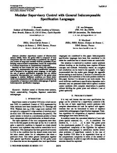
Fig. 1. Model-Based Engineering process with supervisory control synthesis. Icon
modeling, SCT can be applied to automatically synthesize a control function in the form of an automaton, called a supervisor, that restricts the behavior of the plant, such that the system never violates any of the given requirements. The supervisor does not restrict the behavior of the plant more than strictly necessary, which is referred to as a minimally restrictive supervisor [3], [4]. The supervisor can be taken as a starting point for subsequent steps to construct a controller that is optimal with respect to extra-functional criteria such as throughput. With the clear separation between plant and requirements in the modular specification, it becomes easier to deal with changing requirements of the controller. Instead of manual adaptation of the existing supervisor, one can modify the control requirements and automatically generate a new supervisor that is guaranteed to satisfy the evolved requirements. Because requirements can be added in a modular way, they remain traceable in the models. Contributions of the paper: The paper describes the main steps of modeling the wafer logistics in lithography machines in a synthesis-based MBSE framework. Discrete-event models are developed capturing the behavior of the uncontrolled machine and the desired requirements to be imposed onto the system. We show that multiparty synchronization provides clear advantages in terms of modularity, traceability, and adaptability of the model. Modularity is given both by being able to describe the system using a set of loosely coupled, small models, and orthogonally add information about aspects like timing, continuous behavior, and stochastic distributions. We also show that being able to refer to variables and states of automata in guard expressions and state-based requirements, enabled by the use of extended finite automata, provides concise models. It enables a clear separation between observing the system state on the one hand, and enforcing guards on controllable actions on the other hand. Additionally, we show how modular synthesis allows construction of local supervisors that ensure safety of parts of the system for our industrial case where monolithic synthesis is not feasible. II. S YNTHESIS -BASED M ODEL -BASED S YSTEMS E NGINEERING Model-based systems engineering (MBSE) methods are finding their way into industry [11]. In MBSE, the for-
model
denotes documents,
P
integrate realize
denotes models, and
P denotes realizations.
malized application of modeling is used to support system requirements, design, analysis, optimization, validation, and verification activities. Executable models can be created that allow engineers to test the designs before they are actually built. Examples include checking for deadlock-freeness, verifying that all requirements are met, or estimating system performance in various scenarios. Figure 1, introduced in [12], shows the synthesis-based MBSE process. The first step in the design of the system is defining the global requirements R. Then, a high-level design D is created with an abstract decomposition of the various components that are present in the system. For each of these components, a set RS of requirements is modeled in a modular way, and from the plant design DP , a modular model P is made of the plant. These two models together provide the input to the supervisor synthesis step, to generate a supervisor S. Multiparty synchronization of the supervisor with the plant results in the supervised system C (i.e., C = S k P ). The modular approach enables understanding of the architecture, and reasoning about the system in terms of the requirements that are imposed upon it. In the early phases of designing a system, requirements are subject to change and often multiple iterations are needed to obtain the final set of requirements. Having these requirements captured in a modular way allows one to quickly add, adapt, or remove requirements while leaving the rest of the model unaltered. This yields a maintainable system design that is easy to extend and modify. The advantage of using multiparty synchronization is that it makes sure by definition that an action can only be executed if all involved parties are able to execute the action. This allows one to add requirements restricting when a certain action is allowed to occur in a modular fashion. When using asynchronous communication, like channels or broadcasts, this is not the case. When using channels, communication between the plant and requirements is done pairwise. If we have more than two components sharing some action, guards are needed to ensure that the action is enabled in all components. Moreover, a chain of synchronizations is needed to make sure that all components execute the action. The guards are also required when using a broadcast mechanism. It must be guaranteed that all receiving parties are available when executing some action.
Modeling the system using multiparty synchronization also enables the use of supervisory control theory to synthesize a supervisor. The synthesized supervisor is guaranteed to be deadlock-free and correct with respect to the modeled requirements. This differs from model checking [13], [14]. Rather than verifying whether the model satisfies a given requirement, in synthesis all incorrect situations are identified and avoided to guarantee that the resulting system after synthesis never violates any of the given requirements. III. S UPERVISORY C ONTROL T HEORY Given a plant and a set of control requirements, SCT can automatically synthesize a supervisor restricting the plant towards the requirements. If the plant is given as a number of subplants P1 , . . . , Pn , the monolithic plant P is represented by the composition of the subplants P = P1 k · · · k Pn . In SCT, often the term synchronous composition is used rather than multiparty synchronization. They are however equivalent in the sense that execution of shared events among multiple actors is synchronous. Events of the plant are partitioned into two disjoint subsets; the set Σc of controllable events and the set Σu of uncontrollable events. Controllable events can be enforced by the supervisor (e.g. actuator commands), whereas uncontrollable events cannot be inhibited by the supervisor (e.g. changing sensor values). In the SCT framework, the generated supervisor has some useful properties; the supervisor is minimally restrictive (sometimes also called maximally permissive), controllable, and nonblocking. Minimally restrictiveness means that the behavior of the controlled system is not restricted more than strictly necessary to enforce the requirements. Controllability indicates that the supervisor does not block uncontrollable events. Nonblockingness means that the system is always able to finish tasks as required. This is captured using the notion of marked states, that must always be reachable in the controlled system. The original SCT framework has been generalized to extended finite automata [15] for modeling of the plant and requirements. An extended finite automaton [16] is an augmentation of a finite automaton with data variables that can be used in guard formulas and variable updates on event transitions. Furthermore, we can use state-based properties of automata which turns out to be useful to simplify requirement and plant models. For an automaton A with a location l we can use the proposition A.l to denote whether the current state of automaton A is l. We will refer to such propositions as location variables. Using extended finite automata, requirements can often be formulated more concisely [16], [17]. Instead of using automata to express requirements or plant behavior, one can also use state-based expressions [18]. These expressions state the conditions under which an event is allowed to occur. Figure 2 shows a state-based requirement expressed as an automaton (2a) and as expression (2b), stating that event e is only allowed to occur if conditions c1 and c2 are both satisfied.
c1 ∧ c2 e
(a) Automaton
e ⇒ (c1 ∧ c2 ) (b) Expression
Fig. 2. State-based requirement as automaton or expression.
In our case study we use extended finite automata to model the system, using state-based requirements in the form of expressions to specify conditions on the occurence of certain events. By being able to refer to states, these expressions can be formulated very concisely. IV. C ASE STUDY: WAFER FLOW IN LITHOGRAPHY MACHINES
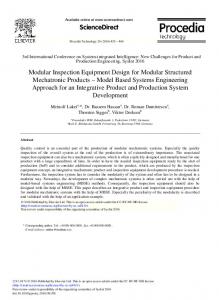
Lithography machines are used in the production process of integrated circuits or chips. They manipulate silicon wafers by exposing them to a light source with nano-scale precision. The integrated circuits are built in a cyclic process, where in each cycle a layer of conducting nano-structures is created. On average, a chip contains more than 30 of these layers. After exposure, the chips are post-processed and finally split into integrated circuits. We describe the wafer flow in a lithography machine, using an abstract interface model of the system as plant. This interface model encapsulates the behavior of the system, and provides an abstract model of the available operations. The wafer routing scheme in the machine is depicted in Figure 3. Wafers are fed into the system from a track (TR). The system itself consists of two operational areas; the wafer stage and the wafer handler. In the wafer stage, wafers are put on a chuck in order to perform the measurement and exposure operations. There are two chucks in the wafer stage, where wafers are measured and exposed in parallel. These two chucks are CH0 and CH1. A chuck has either an expose or measure function, depending on whether the chuck is below the exposure lens or not. The chuck currently having a measure or exposure function is denoted by M, or E, respectively. After one wafer has been measured and another has been exposed, a chuck swap is executed. The exposed wafer returns to the wafer handler, and a new wafer is put onto the chuck for measurement. The life cycle of a wafer in the machine consists of conditioning, alignment, measurement and exposure. The wafer handler is responsible for performing a number of pre-exposure steps on the wafers, and routing wafers from the track to the wafer stage and back. The wafer handler consists of two robots, the load robot (LR) and unload robot (UR), and process and storage locations. At the storage unit bottom (SUB), the wafer is conditioned. This process secures that the temperature of the wafer is within a specific range. At the pre-aligner (PA), a wafer is aligned such that the exact orientation and positioning of the wafer is known for exposure. From the discharge unit (DU), wafers can be picked up by the track. Because immersion lithography is used, a wafer must always be present on the exposure chuck to avoid disruption of the film of water below the lens. Sometimes there can be a
disturbance in the track, which means that delivery of the next production wafer takes slightly longer. Dummy wafers can be inserted into the wafer flow and subsequently be placed on the exposure chuck in order avoid disruption of the film of wafer. Locations CTC0 and CTC1 are the storage locations for these dummy wafers when not used.
A ? s = {A i s ∈ Σc | i ∈ I},
CTC0
DU
A ? e = {A i e ∈ Σu | i ∈ I}, LR
TR
PA
M
E
wafer stage
track SUB
CTC1
of interfaces is used as basis for modeling the wafer flow. We also explain why wafers are explicitly taken into account during synthesis. Resources: Given an activity A involving a wafer, we define the start event set A ? s and the end event set A ? e as
UR
wafer handler
Fig. 3. Wafer routing possibilities
A. Activity Scheduling In the scheduling of the wafer flow, there are two types of activities. On the one hand we have actions that move a wafer from one resource to another. On the other hand we have operations that can be performed on the wafer at a specific resource. Once an activity is started, it must be completed before another activity using the same resource can be started. We make a distinction between starting and ending an activity to keep track of whether an activity is running. The reason that we need this distinction is that when an activity involving a certain resource is started, other activities using this resource are not allowed to start. This assumption avoids situations where the internal state of resources is altered by other activities using the same resource.
where I denotes the finite set of wafer identifiers. The function of the identifiers is explained at the end of this section. Only one activity using resource R can be started at a time, after which this activity must first be completed before another activity also using resource R can be started. We add the constraint that the system must always be able to end an activity once started. This structure is also known as a star interface [19]. Activities not involving a wafer do not have a wafer identifier. One such an activity is a chuck swap. As an example, consider resource CH0 with activities CH0 Measure, CH0 Expose, chuckSwap, LRtoCH0, CH0toLR, and CH0toUR. The corresponding star interface is given in Figure 4. claimed CH0 Measure
CH0 Measure ? s
V. M ODEL S TRUCTURE We model the plant and control requirements in a modular way using extended finite automata. To visualize automata, we use circles for locations, full and dashed labeled arrows for controllable and uncontrollable edges, respectively, incoming arrows for initial locations, and double-lined circles for marked locations. The plant and control requirements are composed using synchronizing parallel composition. In the remainder of this section we describe the interface of the resources containing the provided activities. This set
claimed CH0toUR
CH0toUR ? e
CH0 Expose ? e
CH0toLR ? s
CH0 Expose ? s
CH0toLR ? e
claimed CH0 Expose
claimed CH0toLR
LRtoCH0 ? s chuckSwap e
claimed chuckSwap
B. Assumptions There are a number of important assumptions with respect to the models described in this paper. Since untimed supervisor synthesis is used, all events in the model are untimed. Operations on a wafer are assumed to never fail. In reality, operations such as wafer alignment may fail and wafers are returned to the track unexposed. With respect to the track, we assume that it is always ready to deliver or pick-up a wafer. In future work we plan to extend the model in order to relax these restrictions.
CH0 Measure ? e CH0toUR ? s
LRtoCH0 ? e chuckSwap s
claimed LRtoCH0
Fig. 4. Model Interface CH0: Star interface for resource CH0.
An event set on an edge means that in the model an edge is present for any element in the set. Figure 5 gives an illustration for event set A ? s where I = {1, 2, 3}. A ? s
A 1 s A 2 s A 3 s
Fig. 5. Edge set refinement.
Before starting the execution of an activity, all the required resources must be claimed. When the execution is finished, all claimed resources for the activity are released again. An activity cannot start if one of the resources is not available. Therefore, all resources involved in some activity are claimed at the same time. For the same reason, resources are released at the same time. This is achieved easily using multiparty synchronization.
For the track we have the additional uncontrollable events assignCH0, assignCH1 and assignNoChuckDed. The function of these events is explained in the next section. Wafers: For each wafer we need to keep track of the status in the life cycle and the current position in the system. In the given system it is also possible that a wafer arriving later in the system can overtake a wafer that was already in the system. Therefore, wafers are an explicit part of the model. This also means that the wafers are an explicit part in the synthesis of the supervisor. Because there are nine resources in the machine, at most nine wafers can be present in the system at any point in time. Since there are two dummy wafers in the system, seven production wafers and two dummy wafers are modeled. In this way, an infinite stream of wafers can be simulated using this finite number of wafers. Each wafer is given a unique identifier. Given n production wafers, the production wafers have identifiers 0, . . . , n−1, and the two dummy wafers have identifiers n and n + 1. Therefore the set of wafer identifiers is given by I = {0, . . . , n + 1}. Activities in the system are given an index i to denote that the action is performed on wafer i.
should be carried out. Wafers that are not present in the machine are assumed to reside in the track. 1) Wafer plant: For each wafer we have to keep track of its position in the plant, and the actions that can be executed on the wafer. Figure 7 shows the abstract plant model for a production wafer j. To get the plant automaton, each edge should be replaced by a construct similar to the one shown in Figure 8. Between starting an activity and ending an activity is an intermediate state to indicate that the activity is running. CH0 Measure j s CH0 Expose j s
CTC0
DU
TR
LR
CH0
PA Align j s
PA
UR
SUB
CH1
SUB Cond j s CTC1
CH1 Measure j s CH1 Expose j s
VI. M ODELING Figure 6 shows a decomposition of the complete model into the plant and requirement models. In this overview we have abbreviated Interface r to I r, and ReqOccupied r to R r for each resource r. The top part shows the models for the wafers in the system. For each production wafer j there are seven automata, and for each dummy wafer k there are four. The bottom part shows the models related to the resources in the system. production wafers
dummy wafers
WaferPlant j
AssignChuckDed j
WaferPlant k
ReqLifeCycle j
ObsChuckDed j
ObsAligned k
ObsAligned j
ReqChuckDed j
···
ReqAligned j
ReqAligned k ReqStayInSystem k
resources ChuckDedAss
R LR
R SUB
R CTC0
R TR
R UR
R PA
R CTC1
ReqFIFO I TR
track
R DU
I DU
ReqBreakWater R CH0
S
StoT StoT j s
T StoT j e
Fig. 8. Refinement structure for the edge from S to T.
2) Wafer requirements: Each production wafer goes through the same life cycle of conditioning, alignment, measurement, and exposure. Measurement and exposure can be done on either one of the chucks. After exposure, the wafer must be returned to the track. The alignment accuracy can be lost during the wafer movement. Figure 9 shows the wafer life cycle requirement. Wafer j enters the system after ending activity TRtoSUB. Then the processing steps of the wafer need to be performed in the specified order, after which the wafer leaves the system.
R CH1
BreakWater
I LR
I SUB
I CTC0
I CH0
ActionChucks
I UR
I PA
I CTC1
I CH1
PositionChucks
wafer handler
Fig. 7. Model WaferPlant j: Wafer plant for production wafer j.
CH0 Expose j e, CH1 Expose j e
CH0 Measure j e, CH1 Measure j e CH0 Expose j s, CH1 Expose j s CH0 Measure j s, CH1 Measure j s
DUtoTR j s
wafer stage PA Align j s
Fig. 6. Overview of the complete model.
The remainder of this section contains the plant and requirement models for the wafers and resources.
PA Align j e
TRtoSUB j e
PA Align j s
SUB Cond j s SUB Cond j e
A. Modeling of the production wafers Each action that involves a wafer contains the index of the specific wafer. For instance, action TRtoDU j s denotes the start of the move of wafer j from resource TR to resource DU. Action TRtoDU j e denotes the ending. For each wafer we model the location of the wafer, the actions that can be performed on the wafer and the order in which these actions
Fig. 9. Model ReqLifeCycle j: production wafer life cycle requirement.
If an aligned wafer is picked up by the load robot and put on any resource but one of the chucks, the alignment of the wafer is lost and needs to be redone. If the unload robot picks up the wafer, the alignment is always lost. When any event in set M is executed after finishing the alignment, and before the
measurement step, the alignment needs to be redone. Given the routing possibilities (cf. Fig. 3), we have M = {LRtoDU j s, LRtoPA j s, LRtoCTC0 j s, CH0toUR j s, CH1toUR j s, PAtoUR j s,
track of the chuck dedication status. A variable stores the chuck dedication status, which is updated when the chuck dedication is set using an assignment event. The requirement, shown in Figure 13, enforces that measurement and exposure are only allowed on a dedicated chuck.
SUBtoUR j s, CTC1toUR j s}. Two automata are used to capture that only aligned wafers are allowed to enter the wafer stage. On the one hand, we use a special plant automaton called an observer. This automaton, shown in Figure 10, keeps track of the alignment status of the wafer without restricting the behavior of the plant. On the other hand, we have a state-based requirement ReqAligned j that enforces the constraint that a wafer must be aligned before it can be sent to the wafer stage: LRtoCH0 j s, LRtoCH1 j s ⇒ ObsAligned j.aligned.
This constraint expresses that actions LRtoCH0 j s and LRtoCH1 j s are only enabled if the active state of automaton ObsAligned j is aligned.
M not aligned
aligned PA Align j e M
assignCH0 j, assignCH1 j, assignNoChuckDed j DUtoTR j s DUtoTR j s
not assigned
assigned
assignCH0 j dedication := DedicatedToCH0, assignCH1 j dedication := DedicatedToCH1, assignNoChuckDed j dedication := NoChuckDed
Fig. 12. Model ObsChuckDed j: chuck dedication status of wafer j
CH0 Measure j s, CH0 Expose j s ObsChuckDed j.assigned ∧ (dedication = DedicatedToCH0 ∨ CH1 Measure j s, CH1 Expose j s ObsChuckDed j.assigned ∧ (dedication = DedicatedToCH1 ∨
⇒ dedication = NoChuckDed) ⇒ dedication = NoChuckDed)
Fig. 13. Model ReqChuckDed j: measurement and exposure are only allowed on a dedicated chuck.
PA Align j e
B. Modeling of the dummy wafers Fig. 10. Model ObsAligned j: alignment status of wafer j
As described in Section IV, the integrated circuits on a wafer are built in a cyclic process. Because the chucks might be physically slightly different, there is the possibility that this can cause an overlay error. Therefore, there is an option to enable a mode called chuck dedication. When in this mode, before a wafer enters the system, the track tells the supervisor whether the chuck should be measured and exposed on CH0 or CH1. Events assignCH0 and assignCH1 respectively are introduced for this purpose. Event assignNoChuckDed is introduced for no chuck dedication. The assignment to a chuck is done before a wafer enters the system. Since this behavior is a contract with the track, it is modeled as a plant model shown in Figure 11. assignCH0 j assignNoChuckDed j assignCH1 j TRtoSUB j s
Fig. 11. Model AssignChuckDed j: chuck assignment is done before entering the system.
When the simulated wafer enters the machine again it is assumed to be a new wafer, for which the assignment must again be done. In this way, we can simulate any sequence of assignments of wafers to the chucks. To model the chuck dedication, an observer and requirement model are introduced. The observer, shown in Figure 12, keeps
A dummy wafer has roughly the same plant model as a production wafer with the difference that alignment is the only operation that can be performed on the wafer. Also, both dummy wafers start on either one of the chucks instead of starting at the track. For a dummy wafer there is no life cycle of actions or chuck dedication requirement. However, the requirement that only aligned wafers are allowed to enter the wafer stage also holds for any dummy wafer k (cf. ObsAligned k and ReqAligned k). Furthermore, the dummy wafers are initially aligned because they start on one of the chucks. We have an additional requirement ReqStayInSystem k that dummy wafers are never sent to the track: DUtoTR k s ⇒ false.
C. Modeling of the resources For each resource in the wafer handler or wafer stage, we define a requirement automaton that keeps track of whether the resource contains a wafer or not. When starting an activity that moves a wafer to the resource under consideration, the status becomes occupied. After completion of an activity that takes a wafer from the resource, the resource becomes free again. This requirement is shown in Figure 14. In the wafer stage, there are two chucks that can hold a wafer. A chuck is either at the expose side, where a wafer can be exposed, or at measure side for measurement of the wafer. When at measure side, wafers can also be loaded from and unloaded to the wafer handler. The physical position of the chucks can be swapped using a chuck swap. The plant model
CH0toLR ? s CH0toUR ? s DUtoTR n-1 s
TRtoSUB n-1 s
DUtoTR 2 s
TRtoSUB 2 s
free
LRtoCH0 ? s
occupied DUtoTR 0 s
TRtoSUB 0 s
Fig. 14. Model ReqOccupied CH0: wafer place status of resource CH0.
DUtoTR 1 s
TRtoSUB 1 s
(a) In-order
shown in Figure 15 keeps track of the physical positions of the chucks. This information is used by the requirement shown in Figure 16 to specify the allowed actions on each of the chucks at any point in time.
(b) Out-order
Fig. 18. Model ReqFIFO: FIFO requirement of the track. assignCH0 n-1, assignCH1 n-1, assignNoChuckDed n-1
assignCH0 3, assignCH1 3, assignNoChuckDed 3
TRtoSUB n-1 s chuckSwap s
atExpose chuckSwap e
chuckSwap e
atMeasure chuckSwap s
chuckSwap s
atExpose chuckSwap e
(a) PositionCH0
chuckSwap e
assignCH0 0, assignCH1 0, assignNoChuckDed 0
TRtoSUB 2 s
atMeasure chuckSwap s
(b) PositionCH1
Fig. 15. Model PositionChucks: physical position of the chucks. CH0 Measure i s, CH0toLR ? s, CH0toUR ? s, LRtoCH0 ? s ⇒ PositionCH0.atMeasure CH0 Expose i s ⇒ PositionCH0.atExpose
TRtoSUB 0 s
TRtoSUB 1 s
assignCH0 2, assignCH1 2, assignNoChuckDed 2
assignCH0 1, assignCH1 1, assignNoChuckDed 1
Fig. 19. Model ChuckDedAss: Chuck dedication assignment is only done for the wafer that is next to be sent to the system.
CH1 Measure i s, CH1toLR ? s, CH1toUR ? s, LRtoCH1 ? s ⇒ PositionCH1.atMeasure CH1 Expose i s ⇒ PositionCH1.atExpose Fig. 16. Model ActionsChucks: actions allowed on the chucks.
The breaking of the water layer below the lens is captured using an uncontrollable event breakWater. This event can occur when the chuck below the lens does not contain a wafer, shown in Figure 17. breakWater ⇒ (PositionCH0.atExpose ∧ ReqOccupied CH0.free) ∨ (PositionCH1.atExpose ∧ ReqOccupied CH1.free) Fig. 17. Model BreakWater: when no wafer is below the lens, the water layer can break.
Using an automaton ReqBreakingWafer we can model that this event is never allowed to occur: breakWater ⇒ false.
The interface between the wafer handler and the track adheres to a FIFO requirement. Wafers enter the system in order, and must leave the system in the same order. Figure 18 shows this requirement for n − 1 production wafers. Assignment of the chuck dedication to a wafer is only done for the wafer that is next to be sent to the system. This behavior is modeled as a plant automaton shown in Figure 19. VII. G ENERATION AND VALIDATION OF THE SUPERVISOR A. Simulation After creating models of the system, simulation can be used to validate whether or not they capture the intended behavior.
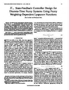
Using simulation one can validate a) whether the plant is a good representation of the real system; and b) whether the controlled system shows the desired behavior. In order to perform such simulation, plants, requirements, and supervisors are described using the Compositional Interchange Format (CIF) [2]. Using the CIF simulator, scenarios can be executed and the evolution of the state of the system is shown in the output. To aid in the validation of the synthesized controller in a more graphical way, the visualization capabilities of the CIF simulator can be used. The CIF simulator provides support for real-time, interactive visualization of the system using user supplied images of the system in standarized SVG (Scalable Vector Graphics) format [20]. A CIF/SVG mapping is used to create a mapping between the model and the visualization. The visualization of the wafer flow in the system is shown in Figure 20. By executing activities during simulation, one can track the flow of wafers and see validate the behavior of the system. The wafer identifiers are also visualized. Production wafers also show the chuck dedication status, which is either CH0, CH1, or ? (no chuck dedication). Colors are used to denote the wafer life cycle status. In order to generate a supervisor using synthesis, the plant model needs to be discrete. However, a system typically consists of both discrete and continuous behavior. The multiparty synchronization mechanism makes it possible to link a discrete abstraction of the plant to a full hybrid plant model in a modular fashion. Continuous variables can be used whose values are described by a set of differential equations. Such models are similar to the hybrid automata formalism [21].
CTC0 CH1
1 CH0
DU CH0
*
2
3
7
Expose
LR
CH0
6
CH1 PA
0
TR
UR *
5
CH0
4
SUB
Measure CH1
8 CTC1
Fig. 20. Visualization of the wafer flow in the system.
t ≥ timeChuckSwap chuckSwap e
t ≥ T chuckSwap e
chuckSwap s t := 0
chuckSwap s t := 0; T := sample(normal(4,0.003))
(a) Fixed timing
(b) Stochastic timing distribution
Fig. 21. Timing model for the chuck swap activity with continuous variable t having a derivative of 1.
supervisory control architectures [23], [24] can be used. In such frameworks, modular supervisors are created for local subsystems to enforce local requirements. A global supervisor is computed based on abstractions of these to enforce requirements on multiple subsystems. These abstractions need to adhere to certain conditions to ensure that nonblockingness, minimal restrictiveness and controllability still hold at a global level [23], [24]. To enforce these global properties, a highlevel coordinator might also be needed that orchestrates the interaction between local supervisors. Modular synthesis often results in a more efficient synthesis step when the decomposition is chosen carefully, such that subsystems internally share a lot of events while the set of events shared among subsystems is small. The modular supervisors that are generated are also easier to understand for the designer of the system, because the guards generated for events are typically fairly small. There are also techniques to obtain very concise guards for events [25]. For the model presented in this paper, we have created modular supervisors for the wafer stage and the individual wafers. This corresponds to the dashed part of the model shown in Figure 22. production wafers
dummy wafers
WaferPlant j
AssignChuckDed j
ReqLifeCycle j
ObsChuckDed j
ObsAligned j
ReqChuckDed j
WaferPlant k ···
ReqAligned j
ObsAligned k ReqAligned k ReqStayInSystem k
resources
By adding continuous dynamics to the model it becomes possible to link the supervisor and discrete plant abstraction to actuators and sensors present in the system like (servo) motors, cylinders, hydraulic drives or optical sensors. Figure 21 shows an example of hybrid models describing timing information about the chuck swap. Because of the multiparty synchronization mechanism, these models can be added to the model without requiring any changes to the original model and the events are automatically synchronized. B. Synthesis In order to obtain a correct supervisor for the system, synthesis can be used. Due to the large size of the complete model, however, monolithic synthesis was not feasible. We tried monolithic synthesis on the complete model, without the alignment models (c.f. ObsAligned i and ReqAligned i for each wafer i) using extended-finite automata synthesis in Supremica [22]. Synthesis of two production wafers and two dummy wafers succeeded within 1,5 hours on 4 Intel E5-2630 CPUs with 80GB of available virtual memory. The state space for this model has a size of 1.9·107 states. For more production wafers, the available memory was not sufficient. Models of the plant and the requirements are however made in a modular way. This means that some requirements can be enforced locally on subsystems, whereas other requirements entail multiple subsystems and need to be enforced globally. Rather than using monolithic synthesis, hierarchical, modular
ChuckDedAss
R LR
R SUB
R CTC0
R TR
R UR
R PA
R CTC1
ReqFIFO
R DU
I TR
track
I DU
ReqBreakWater R CH0
R CH1
BreakWater
I LR
I SUB
I CTC0
I CH0
ActionChucks
I UR
I PA
I CTC1
I CH1
PositionChucks
wafer handler
wafer stage
Fig. 22. Modular synthesis for part of the model.
These supervisors ensure that certain local requirements are never violated. For the wafer stage we have synthesized a supervisor given all models related to the wafer stage using Supremica. This supervisor enforces the following guard on the controllable action chuckSwap s: ¬ ReqOccupied CH0.free ∧ ¬ ReqOccupied CH1.free
This means that a chuck swap is only allowed when both chucks contain a wafer. Only in that case, it is ensured that both before and after the swap a wafer is present below the exposure lens. Therefore, the water layer below the lens will never break according to model BreakWater. For each wafer we synthesize a modular wafer supervisor, which can be added to the model. These supervisors ensure that wafers follow their life cycle, and satisfy the alignment and chuck dedication requirements. Synthesis of these local supervisors is done within a few seconds. The modular wafer supervisors and wafer stage supervisor are not sufficient to guarantee global properties like absence
of deadlocks in the system. Figure 20 shows an example of this, where no wafer movement is possible. Wafer 3 is not aligned and can therefore not be moved to a chuck. Wafer 2 cannot be brought to the track because it is not yet exposed. The only possible action is re-alignment of wafer 0. Future work will look at hierarchical, modular supervisory control approaches for the complete model using various aggregations of the models that ensure the global properties nonblockingness, controllability, and minimal restrictiveness. We will evaluate these approaches in terms of computational efficiency. VIII. E VALUATION In Section VI, we have shown how a discrete product flow can be modeled where each of the products has a certain life cycle in the system. The capabilities of the system and the imposed requirements are modeled in a modular, compositional way. Also information about timing, hybrid dynamics, and stochasticity can be added to the model in a modular fashion (cf. Section VII) without changing the original model. By using multiparty synchronization all submodels can be linked in a straightforward manner. Requirements specifying orthogonal aspects can be captured as separate submodules, for instance the requirements related to chuck dedication and the alignment of a wafer. All requirements remain traceable in the model, because they are specified and added as separate submodules. The compositionality of this style makes it appropriate for incremental specification of the system. If the model needs to be adapted due to changed, added, or removed requirements, only the model of the specific requirement needs to be adapted locally. State-based requirements allow a concise way of modeling the conditions under which an event is allowed to occur. Many of the requirements in our case study can be expressed using this mechanism. The main reason for this conciseness is the ability to refer to the value of variables, and location variables to refer to locations in any automaton in the model. For instance in the ReqChuckDed model shown in Figure 13, both are used. Here, the requirement itself does not have to keep track of the chuck dedication status to restrict when measurement and exposure are allowed on a specific chuck. For industrial-size systems, such as the one in this paper, monolithic synthesis is often not achievable. Rather than synthesizing a single monolithic supervisor, a modular synthesis approach can be used. Here, local supervisors are created to enforce local requirements, and global supervisors enforce requirements that deal with multiple subsystems. Choosing the right hierarchical decomposition of the control architecture can have a big impact on the computational complexity. IX. R ELATED WORK The modeling approach used in synthesis-based MBSE resembles the constraint-oriented style that is one of the prominent modeling styles in the specification language LOTOS [26], [27]. One of the critera for using this style is the ability to identify orthogonal functions of the system by
separate constraints. It enables understanding and reasoning of the system in terms of the requirements imposed on it and the relationships between requirements. These observations are in accordance with the observation obtained in our case study. Although supervisor synthesis is a well-established field of research, the number of industrial applications described in the literature is still limited. There are case studies in the coordination of exception handling in printers [28], movement coordination of theme park vehicles [29] and a patient support table for an MRI scanner [17], [30], and the design of smart homes for disabled people [31]. Without claiming completeness, there are also several applications of supervisor synthesis in automated manufacturing and assembly systems: [32]–[34]. Other prominent modeling platforms for supervisory controller design are Matlab/Simulink [35] and SCADE [36]. A fundamental difference with respect to SCT described in this paper is that they provide tools and methodologies to support the process of manual development of system models, but they do not support automatic synthesis of a correct supervisor as enabled by supervisory control synthesis. Statebased requirements are supported by Simulink but not by SCADE. Both tools do not support multiparty synchronization. In our proposed supervisory control framework, only safe system behavior is taken into account. Extensions to the theory have been proposed to increase expressiveness of the control requirements, for instance enforcement of fairness and liveness [37]–[40], and timing [41] properties. In high-tech systems also performance criteria such as maximization of the throughput have to be met, which has been investigated by Shehabinia et al. [42]. X. C ONCLUSION This paper’s main thesis is that the modeling approach in synthesis-based MBSE using multiparty synchronization is very well suited for the development of supervisory controllers, exhibiting clear advantages in terms of traceability, modularity and adaptability of the requirements. Using this approach, problems of industrial size can be modeled concisely using a set of small automata that together capture the desired behavior of the system. State-based expressions provide a mechanism to model requirements very concisely, enabled by location variables that allow to refer to states. Synthesized supervisors for parts of the model can be put in parallel with the complete model to enable validation through simulation. Supervisor synthesis for the complete model is not feasible with current monolithic synthesis algorithms. Future work is needed to explore steps to derive a supervisor more efficiently using modular synthesis algorithms. The industrial case study presented in this paper has various aspects that are present in almost any manufacturing system, like resources, activities, and product life cycles. It might be expected that the advocated modeling approach has similar advantages when applied to other manufacturing systems. Future work includes looking at modular synthesis techniques for the complete model. We will also investigate the extension towards timed supervisory control and optimization with respect to
throughput. This optimization is crucial in the wafer logistics of lithography machines to maximize the number of wafers that can be exposed per time unit. ACKNOWLEDGMENT This research is supported by the Dutch Technology Foundation STW, carried out as part of the Robust Cyber-Physical Systems (RCPS) project, project number 12693. Further support is given by the EU FP7 Programme under grant agreement No. 295261 (MEALS). R EFERENCES [1] J. Baeten, J. van de Mortel-Fronczak, and J. Rooda, “Integration of supervisory control synthesis in model-based systems engineering,” Proc. of Special International Conference on Complex Systems: Synergy, of Control, Communications and Computing, pp. 167–178, 2011. [2] D. A. van Beek, W. J. Fokkink, D. Hendriks, A. Hofkamp, J. Markovski, J. M. van de Mortel-Fronczak, and M. A. Reniers, “CIF 3: Model-based engineering of supervisory controllers,” in Tools and Algorithms for the Construction and Analysis of Systems, ser. Lecture Notes in Computer Science. Springer Berlin Heidelberg, 2014, vol. 8413, pp. 575–580. [3] P. J. G. Ramadge and W. M. Wonham, “Supervisory control of a class of discrete event processes,” SIAM J. Control Optim., vol. 25, no. 1, pp. 206–230, 1987. [4] ——, “The control of discrete event systems,” Proc. of the IEEE, vol. 77, no. 1, pp. 81–98, 1989. [5] C. G. Cassandras and S. Lafortune, Introduction to Discrete Event Systems, Second Edition. Springer, 2008. [6] J. O. Moody and P. J. Antsaklis, Supervisory Control of Discrete Event Systems Using Petri Nets. Norwell, MA, USA: Kluwer Academic Publishers, 1998. [7] B. De Schutter and T. van den Boom, “Max-plus algebra and max-plus linear discrete event systems: An introduction,” in Workshop on Discrete Event Systems, May 2008, pp. 36–42. [8] J. C. M. Baeten, T. Basten, and M. A. Reniers, Process Algebra: Equational Theories of Communicating Processes, 1st ed. New York, NY, USA: Cambridge University Press, 2009. [9] P. Cuijpers and M. Reniers, “Hybrid process algebra,” Journal of Logic and Algebraic Programming, vol. 62, no. 2, pp. 191 – 245, 2005. [10] S. L. Ricker and K. Rudie, “Know means no: Incorporating knowledge into discrete-event control systems,” Automatic Control, IEEE Trans. on, vol. 45, no. 9, pp. 1656–1668, Sep 2000. [11] J. Estefan, Survey of Model-Based Systems Engineering (MBSE) Methodologies, rev. b. ed., International Council on Systems Engineering (INCOSE), Seattle, WA, USA, 2008. [12] R. R. Schiffelers, R. J. M. Theunissen, D. A. van Beek, and J. E. Rooda, “Model-based engineering of supervisory controllers using CIF,” Electronic Communications of the EASST, vol. 21, 2010. [13] E. M. Clarke and E. A. Emerson, “Design and synthesis of synchronization skeletons using branching-time temporal logic,” in Logic of Programs, Workshop. London, UK, UK: Springer-Verlag, 1982, pp. 52–71. [14] J. P. Queille and J. Sifakis, “Specification and verification of concurrent systems in CESAR,” in International Symposium on Programming, ser. Lecture Notes in Computer Science. Springer Berlin Heidelberg, 1982, vol. 137, pp. 337–351. ˚ [15] S. Miremadi, B. Lennartson, and K. Akesson, “A BDD-based approach for modeling plant and supervisor by extended finite automata,” Control Systems Technology, IEEE Trans. on, vol. 20, no. 6, pp. 1421–1435, Nov 2012. ˚ [16] M. Skoldstam, K. Akesson, and M. Fabian, “Modeling of discrete event systems using finite automata with variables,” in Decision and Control, 2007 46th IEEE Conference on, Dec 2007, pp. 3387–3392. [17] R. Theunissen, D. van Beek, and J. Rooda, “Improving evolvability of a patient communication control system using state-based supervisory control synthesis,” Advanced Engineering Informatics, vol. 26, no. 3, pp. 502 – 515, 2012, evolvability of Complex Systems. [18] J. Markovski, D. van Beek, R. Theunissen, K. Jacobs, and J. Rooda, “A state-based framework for supervisory control synthesis and verification,” in Decision and Control, 2010 49th IEEE Conference on, Dec 2010, pp. 3481–3486.
[19] R. J. Leduc, B. A. Brandin, M. Lawford, and W. M. Wonham, “Hierarchical interface-based supervisory control-part i: serial case,” Automatic Control, IEEE Trans. on, vol. 50, no. 9, pp. 1322–1335, Sept 2005. [20] W3C, “Scalable Vector Graphics (SVG) W3C recommendation,” 2011. [21] R. Alur, C. Courcoubetis, N. Halbwachs, T. A. Henzinger, P.-H. Ho, X. Nicollin, A. Olivero, J. Sifakis, and S. Yovine, “The algorithmic analysis of hybrid systems,” Theoretical Computer Science, vol. 138, no. 1, pp. 3–34, 1995. ˚ [22] K. Akesson, M. Fabian, H. Flordal, and R. Malik, “Supremica - an integrated environment for verification, synthesis and simulation of discrete event systems,” in Workshop on Discrete Event Systems, July 2006, pp. 384–385. [23] L. Feng and W. Wonham, “Supervisory control architecture for discreteevent systems,” Automatic Control, IEEE Trans. on, vol. 53, no. 6, pp. 1449–1461, 2008. [24] K. Schmidt and C. Breindl, “Maximally permissive hierarchical control of decentralized discrete event systems,” Automatic Control, IEEE Trans. on, vol. 56, no. 4, pp. 723–737, 2011. [25] S. Miremadi, K. Akesson, and B. Lennartson, “Symbolic computation of reduced guards in supervisory control,” Automation Science and Engineering, IEEE Trans. on, vol. 8, no. 4, pp. 754–765, Oct 2011. [26] C. A. Vissers, G. Scollo, M. Van Sinderen, and E. Brinksma, “Specification styles in distributed systems design and verification,” Theoretical Computer Science, vol. 89, no. 1, pp. 179–206, 1991. [27] K. J. Turner, “Constraint-oriented style in LOTOS,” British Computer Society Workshop on Formal Methods and Standards, pp. 1–13, 1988. [28] E. Bertens, R. Fabel, M. Petreczky, D. van Beek, and J. Rooda, “Supervisory control synthesis for exception handling in printers,” in Proc. Philips Conference on Applications of Control Technology, 2009. [29] S. T. Forschelen, J. M. Mortel-Fronczak, R. Su, and J. E. Rooda, “Application of supervisory control theory to theme park vehicles,” Discrete Event Dynamic Systems, vol. 22, no. 4, pp. 511–540, Dec. 2012. [30] R. Theunissen, M. Petreczky, R. Schiffelers, D. van Beek, and J. Rooda, “Application of supervisory control synthesis to a patient support table of a magnetic resonance imaging scanner,” Automation Science and Engineering, IEEE Trans. on, vol. 11, no. 1, pp. 20–32, Jan 2014. [31] S. Guillet, B. Bouchard, and A. Bouzouane, “Correct by construction security approach to design fault tolerant smart homes for disabled people,” Procedia Computer Science, vol. 21, pp. 257 – 264, 2013. [32] J.-F. P´etin, D. Gouyon, and G. Morel, “Supervisory synthesis for product-driven automation and its application to a flexible assembly cell,” Control Engineering Practice, vol. 5, no. 5, pp. 595 – 614, 2007. [33] M. Nourelfath and E. Niel, “Modular supervisory control of an experimental automated manufacturing system,” Control Engineering Practice, vol. 12, no. 2, pp. 205 – 216, 2004. [34] M. H. de Queiroz and J. E. R. Cury, “Synthesis and implementation of local modular supervisory control for a manufacturing cell,” in Workshop on Discrete Event Systems, 2002, pp. 377–382. [35] Mathworks, “Simulink: Simulation and model-based design,” 2015. [36] Esterel Technologies, “SCADE,” 2015. [37] N. D’Ippolito, V. A. Braberman, N. Piterman, and S. Uchitel, “Synthesizing nonanomalous event-based controllers for liveness goals,” ACM Trans. Softw. Eng. Methodol., vol. 22, no. 1, p. 9, 2013. [38] P. Gohari and W. M. Wonham, “Efficient implementation of fairness in discrete-event systems using queues,” Automatic Control, IEEE Trans. on, vol. 50, no. 11, pp. 1845–1849, Nov 2005. [39] A. van Hulst, M. Reniers, and W. Fokkink, “Maximally permissive controlled system synthesis for modal logic,” in SOFSEM 2015: Theory and Practice of Computer Science, ser. Lecture Notes in Computer Science. Springer Berlin Heidelberg, 2015, vol. 8939, pp. 230–241. [40] ——, “Maximal synthesis for Hennessy-Milner logic,” ACM Trans. Embedded Comput. Syst., vol. 14, no. 1, pp. 10:1–10:21, 2015. [41] B. A. Brandin and W. M. Wonham, “Supervisory control of timed discrete-event systems,” Automatic Control, IEEE Trans. on, vol. 39, no. 2, pp. 329–342, 1994. [42] A. R. Shehabinia, L. Lin, R. Su, and C. S. Chong, “Supervisory control for a class of discrete event systems for optimal throughput,” in Workshop on Discrete Event Systems, vol. 12, 2014, pp. 201–207.