An Optimal Load-Frequency Control Method for Inverter-Based Renewable Energy Transmission
Kirsch Mackey and Roy A. McCann Department of Electrical Engineering University of Arkansas Fayetteville, AR USA
[email protected]
Abstract—The frequency droop response of conventional turbine driven synchronous generators with respect to load increases is normally used in order to have stable operating characteristics for multiple generators operating in parallel over large geographical regions. This presents a challenge for renewable energy sources that interface to the transmission grid through static inverters that do not exhibit an intrinsic frequency droop characteristic. This paper provides a technique for designing optimal load frequency controllers as transmission line inverters fed from renewable energy sources that allows for fast dynamic response due to variable solar and wind conditions while maintain stability to interconnected synchronous generators. A control technique based on LQG optimization theory is presented. Detailed analysis of a threearea system in a region of mixed wind and solar photovoltaic sources is modeled in a manner that confirms the effectiveness of the disclosed load-frequency control method.
I.
INTRODUCTION
Increasing use of renewable energy sources such as wind and solar often requires transmission of electricity over distances where complex inter-area power flow interactions occur with conventional generation. This is due in part to the abundance of renewable energy sources in rural areas, such as the case of the central and southwestern United States that are far removed from major population centers. Whenever EHV transmission line lengths exceed 250 km then interarea frequency stability becomes a concern. In the case of conventional turbine0driven synchronous generators, th9ere is an extensive theory for developing feedback controllers to ensure stable operation of the transmission grid as described in [1] and [2]. For conventional synchronous generators, a frequency-droop characteristic is designed such that frequency decreases as load increases, thereby leading to load sharing between parallel connected machines. However, for static inverters commonly used for interfacing renewable electric power sources such as photovoltaics and wind, the power electronics has no such intrinsic response. This can lead to stability in power flow control and load sharing between renewable and conventional generation as described in [3], [4] and [5]. This has motivated the development of solutions such as those found in [6] and [7]. However, a virtual-droop characteristic can be programmed as part of the inverter operation that approximates the load sharing properties of synchronous generators. This paper considers a stochastic approach that incorporates the probabilistic nature
of wind and solar sources to design the controller coefficients. In addition, the availability of synchrophasors along with smart grid technologies enables the communication of angle and frequency measurements with minimal time-delay. That is, the research proposes that stochastic optimal control theory can be applied to improve the stability performance of interconnected renewable energy sources in order to achieve proper load-frequency regulation objectives. II.
MODELING OF INTER-AREA DYNAMICS
The following modeling of inter-area dynamics used in this research is developed in the manner detailed by Murty in [8]. In this research the time-constants and parameters are modified to match the faster response times associated with static inverters as described by [9]. This paper considers a three-area load-frequency control system. The most general case allows for inter-tie power flows between any two areas. This is shown in terms of Laplace-domain block diagram form in Fig. 1. The corresponding transfer functions are given in [8] by, KP1 ∆F1 (s) = �∆PG1 − ∆PD1 − ∆Ptie,1 � (1) ∆F2 (s) = ∆F3 (s) =
1 + sTP1 KP2
∆SV1 (s) = ∆SV2 (s) = ∆SV3 (s) =
1 + sTP2 KP3 1 + sTP3 1
�∆PG2 − ∆PD2 − ∆Ptie,2 � �∆PG3 − ∆PD3 − ∆Ptie,3 �
1 + sTS1 1 1 + sTS2 1 1 + sTS3
�∆PC1 (s) − �∆PC2 (s) − �∆PC3 (s) −
∆PG1 (s) = ∆PG2 (s) = ∆PG3 (s) =
∆Ptie,1 =
∆Ptie,2 =
2πT0 12 s
2πT0 21 s
1
1 + sTTG1 1 1 + sTTG2 1 1 + sTTG3
1
R1 1 R2 1 R3
(2) (3)
∆F1 (s)�
(4)
∆F3 (s)�
(6)
∆F2 (s)�
∆XV1 (s) ∆XV2 (s) ∆XV3 (s)
[∆F1 (s) − ∆F2 (s)] +
(7) (8) (9)
2πT0 13
∆F3 (s)]
[∆F2 (s) − ∆F1 (s)] +
(5)
s
2πT0 23 s
[∆F1 (s) −
(10)
[∆F2 (s) −
∆F3 (s)] (11)
∆PC1
+
1 R1
∑
∆PD1
GC1(s)
GT1(s)
∑
∆F1(s)
GP1(s)
∆F1(s) 1 s
∆PC2
+
1 R2
∑
∑ +
0 2πT12
∑
-
+
0 2πT13
∑ -
∆PD2
GC2(s)
GT2(s)
∑
∆F2(s)
GP2(s)
∆F2(s) 1 s
∆PC3
+
1 R3
∑
∑ +
0 2πT21
∑
-
+
0 2πT23
∑ -
∆PD3
GC3(s)
GT3(s)
∑
∆F3(s)
GP3(s)
∆F3(s) 1 s
0 2πT31
∑
0 2πT32
∑ +
-
+
∑ -
Figure 1. Three-area load-frequency control block diagram [8].
∆Ptie,3 =
2πT0 31 s
[∆F3 (s) − ∆F2 (s)] +
2πT0 32
∆F2 (s)]
s
[∆F3 (s) − (12)
These can be converted into time-domain state equations as derived in [8], ∆f1̇ =
∆ḟ2 = ∆ḟ3 =
1
TP1 1
TP2 1
TP3
∆ṖG1 =
�−∆f1 + K P1 ∆PG1 − K P1 ∆PD1 − K P1 ∆Ptie,1 �
∆ṖG2 = ∆ṖG3 =
∆Ẋ V1 = ∆Ẋ V2 = ∆Ẋ V3 =
1
TT2 1 TT3 1
∆Ṗtie,1 =
TS1 1 TS2 1 TS3
(−∆PG2 + ∆XV2 )
(17)
(−∆PG3 + ∆XV3 )
(18)
�−∆XV1 + ∆PC1 − �−∆XV2 + ∆PC2 − �−∆XV3 + ∆PC3 −
0 (∆f 2πT12 1
− ∆f2 ) +
1
R1 1 R2 1 R3
∆f1 �
(19)
∆f2 � ∆f3 �
0 (∆f 2πT13 1
(20) (21) − ∆f3 )
(22)
(13) �−∆f2 + K P2 ∆PG2 − K P2 ∆PD2 − K P2 ∆Ptie,2 �
0 (∆f 0 ∆Ṗtie,2 = 2πT21 2 − ∆f1 ) + 2πT23 (∆f2 − ∆f3 ) (23)
(15) (16)
These can be more compactly written in matrix-vector form as,
(14) �−∆f3 + K P3 ∆PG3 − K P3 ∆PD3 − K P3 ∆Ptie,3 �
1
TT1
(−∆PG1 + ∆XV1 )
0 (∆f 0 ∆Ṗtie,3 = 2πT31 3 − ∆f1 ) + 2πT32 (∆f3 − ∆f2 ) (24)
d
CT
150 mi.
PQ Loads r
C
u
𝐱̇ = 𝐀𝐀 + 𝐁𝒖 + 𝐅𝒅
y WT PV
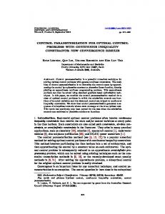
Figure 3. Three-area load-frequency control application.
Figure 2. Optimal controller configuration.
𝐱̇ = 𝐀𝐱 + 𝐁𝐮 + 𝐅𝐝
(25)
where the state vector is
xT = �∆f1 ∆f2 ∆f3 ∆PG1 ∆PG2 ∆PG3 ∆PV1 ∆PV2 ∆PV3 ∆Ptie,1 ∆Ptie,2 ∆Ptie,3 �
(26) And the control inputs are the commanded power provided by each source, T
u = [∆PC1 ∆PC2 ∆PC3 ] ,
(28)
with measurable states that can be used for feedback control purposes, y T = �∆f1 ∆f2 ∆f3 ∆Ptie,1 ∆Ptie,2 ∆Ptie,3 � .
(29)
The availability of (29) for feedback control is justified by the specifications for IEEE C37.118 compliant phasor measurement units where time latency and accuracy are minimized [12]. III.
A − BK x − LC + LDK x −BK i + LDK i x� x�̇ �� � + � �=� xi 0 0 ẋ i 0 L r � �� � (30) I −I y
The controller is defined as a proportional-integral PI compensator, u = [−K x
(27)
and the system responds to changes in demanded loads as disturbance inputs to the system, dT = [∆PD1 ∆PD2 ∆PD3 ] ,
PQ Loads
STOCHASTIC OPTIMAL CONTROL
The statistical characteristics of the disturbance inputs of wind and solar generating levels can be collected and analyzed. Given the mean and variance calculations from the generating historical data, a linear quadratic Gaussian (LQG) controller can be developed [10]. The controller includes a Kalman filter that estimates the system state variables that are not directly measureable as 𝑥�. In order to reduce the steady-state frequency to zero (that is, to provide frequency regulation capability for each area), the integral if each area’s frequency error is defined as state augmented variables 𝑥𝑖 ,
x� −K i ] � � xi
(31)
The LQG controller employs statistical characteristics of the system in order to develop the optimal state estimate and controller gains [6]. The statistical model is derived using historical data collected from the operational PMU data that has been collected from the same system that requires stabilization. A block diagram showing the controller LQG controller structure is shown in Fig. 2. IV.
EVALUATION OF OPTIMAL LOAD-FREQUENCY CONTROL
Parameter values are selected that correspond to a threearea system as shown in Fig. 3. Area-1 consists of 600 MW wind-turbine generators (WTG) with Type-4 doubly-fed induction generators. Area 2 consists of local loads along with 400 MW of solar photovoltaic (PV) generation with local real and reactive (PQ) loads. Area 3 has 800 MW of conventional combustion turbines (CT) and local PQ loads. The three areas are interconnected with long transmission lines. The effects of PV fluctuations are examined with and without the LQG load-frequency control of the static inverters located in Area 1 and Area 2. Figures 4 and 5 indicate the frequency and intertie-line transients respectively, in the wind turbine area (WTG) Area-1 after a 50% reduction in rated solar PV power in Area 2. It is observed that the LQG controller provides significantly better regulation in the frequency and power stability performance in the neighboring WTG area. The corresponding transient in
Control Area Three 0.04
0.035
0.035
0.03
0.03
0.025
0.025 Frequency (Hz)
Frequency (Hz)
Wind Generation Control Area 0.04
0.02 0.015
0.02 0.015
0.01
0.01
0.005
0.005
0
0
-0.005
0
5
10
-0.005
15
0
5
Figure 4. WTG frequency transient due to 50% PV reduction in Area-2. -3
15
Figure 6. CT frequency transient due to 50% PV reduction in Area-2. -3
Wind Generation Control Area
x 10
10 Time (s)
Time (s)
2
Control Area Three
x 10
18 0
14
Tie Line Power 3 (per unit)
Tie Line Power 2 (per unit)
16
12 10 8 6 4 2
-2
-4
-6
-8
0 -2
0
5
10
-10
15
Figure 5. WTG intertie-line power due to 50% PV reduction in Area-2.
intertie-line power and frequency of Area-3 is shown in Figs. 6 and 7, respectively. The LQG controller provides improved damping of the inter-area power flows as well as improved stability of the CT frequency.
15
REFERENCES [1] [2]
CONCLUSIONS
A method for modeling multi-area load-frequency dynamics is provided that accounts for the dynamics of static inverters. The frequency droop characteristics that are defined for conventional synchronous generators are adapted to power electronic inverters with a stochastic optimal control method that includes the faster time constants associated with most inverter circuits. Simulation results confirm the benefits of this method for a three area loadfrequency control system where improved ability to include renewable energy sources is demonstrated.
10
5
Figure 7. CT intertie-line power transient due to 50% PV reduction in Area-2.
[3]
V.
0
Time (s)
Time (s)
[4]
[5]
[6]
P. Sauer and M. Pai, Power System Dynamics and Stability, PrenticeHall, NY, 1997. M. Ibrahim, Disturbance Analysis for Power Systems, New York: Wiley-IEEE Press, 2012. E. Vittal, M. O'Malley, and A. Keane, "Rotor Angle Stability With High Penetrations of Wind Generation," IEEE Transactions on Power Systems, vol. 27, no. 1, pp. 353 - 362, February 2012. M. Reza, D. Sudarmadi, F.A. Viawan, W.L. Kling, and L. Van Der Sluis, "Dynamic Stability of Power Systems with Power Electronic Interfaced DG," in Power Systems Conference and Exposition, 2006, Atlanta, 2006, pp. 1423 - 1428. A.K. Srivastava, A.A. Kumar, and N.N. Schulz, "Impact of Distributed Generations with Energy Storage Devices on the Electric Grid," IEEE Systems Journal, vol. 6, no. 1, pp. 110 - 117, March 2012. W. Du, H.F. Wang, J. Cao, H.F. Li, and L. Xiao, "Application of the Phase Compensation Method for the Design of a DC/AC ConverterBased Stabilizer to Damp Inter-Area Power Oscillations," IEEE Transactions on Power Systems, vol. 27, no. 3, pp. 1302 - 1310, August 2012.
[7]
[8] [9]
O. Leiterman and J.L. Kirtley, "Energy Storage for Use in Load Frequency Control," in Innovative Technologies for an Efficient and Reliable Electricity Supply (CITRES), Cambridge, 2010, pp. 292-296. P.S.R. Murty, Operation and Control in Power Systems, CRC Press, Boca Raton, FL, 2011. Y. Shuito, Q. Lei, F. Peng, and Z. Qian, “A robust control scheme for grid-connected voltage-source inverters,” IEEE Transactions on Industrial Electronics, vol. 58, no. 1, pp. 202-212, Jan. 2011.
[10] F. L. Lewis, D. Vrabie and V.L. Syrmos, Optimal Control, 3rd Edition, New York: Wiley, 2012. [11] W. Du, H.F. Wang, J. Cao, H.F. Li, and L. Xiao, "Application of the Phase Compensation Method for the Design of a DC/AC ConverterBased Stabilizer to Damp Inter-Area Power Oscillations," IEEE Transactions on Power Systems, vol. 27, no. 3, pp. 1302 - 1310, August 2012. [12] Standard for Synchrophasors for Power Systems, IEEE C37.1182005, New York, March 2006.