Vinit Kumar Dhull et al. / International Journal on Computer Science and Engineering (IJCSE)
An Optimized Deployment Approach for Intercloud and Hybrid cloud Vinit Kumar Dhull Department of Computer Science & Engineering Jamia Hamdard (Hamdard University), New Delhi, India
[email protected]
Shah Imran Alam Department of Computer Science & Engineering Jamia Hamdard (Hamdard University), New Delhi, India
[email protected]
Syed Imtiyaz Hassan Department of Computer Science & Engineering Jamia Hamdard (Hamdard University), New Delhi, India
[email protected] Abstract—This paper will illustrate the associated issues with multi-tier enterprise applications in the cloud when the tiers need to distribute geographically as in multicloud and hybrid cloud. The end-to-end response time for such application will largely depend on network delays as the control moves from one tier to the other tier. An effort made by proposing a simplistic deployment pattern to mitigate the delay in response time by minimizing the network communication between geographically distributed nodes of inter-tier clusters. A deployment pattern proposed in paper attempts to combine the functionality of specialized nodes of different tiers into a more generalized, multi-purpose node cluster to the possible extent. A formalization of the gain in response time based on the experiment incorporating three deployment models of the cloud for a web application. A detailed analysis presented at communication time of the different deployment model and results used to understand and draw conclusions to determine the benefit of proposed deployment pattern. Keywords- Multi-tier architecture; Application deployment; Cloud; Deployment models; Multicloud; Hybrid cloud. I. INTRODUCTION Cloud computing is a model for empowering omnipresent, on-request access to a mutual pool of configurable registering assets (e.g., computer networks, servers, storage, applications, and services) which can be quickly provisioned and discharged with negligible administration exertion [1]. There are three major types of deployment models in the cloud. Private cloud will be cloud foundation worked exclusively for a solitary association, whether oversaw inside or by an outsider and facilitated either inside or remotely[2]. In public cloud, the services rendered over a system that is open for public utilize. Public cloud services may be free [3]. Hybrid cloud is a composition of two or more clouds (private, community or public) that remain distinct entities but bound together, offering the benefits of multiple deployment models. Cloud has become a preferred platform for a various range of applications and one of the most prominent is business applications. Deploying such, applications have high cost and might need to scale quickly. Among all range of applications, enterprise level applications are typically large applications with more intense needs towards scalability and high performance thus pushing them for horizontal scaling with multi-tier distribution leading to clustering at the level of each tier. A typical multi-tiered application consists of Presentation Layer, Business Logic Layer, and Data Access Layer. Moreover, for high-performance, these tiers distributed over several machines across the network. In the cloud, performance becomes major issues, as response time would largely depend on communication delays between these layers, where different tiers are geographically distributed. Different applications developed according to organization requirements and deployed in the cloud, according to their architecture. Standards are required for deploying the applications in geographically distributed clouds. Few standards regarding interoperability in cloud computing is described by [4].
ISSN : 0975-3397
Vol. 9 No.05 May 2017
266
Vinit Kumar Dhull et al. / International Journal on Computer Science and Engineering (IJCSE)
Multi-tier architecture (n-tier architecture) is the client–server architecture. A developer uses a model provided by N-tier application architecture to create reusable and flexible applications. N-tier gives the option for adding or modifying a specific layer, without rewriting the entire application. These individual layers require scaling in Ntier architecture when there is a rise in workload on them. It might be possible that there is a need for scaling of only one layer, which is facing a more intensive request. This service-oriented or loosely coupled approach allows architects to scale components independently and enabling systems to scale at extraordinary levels. Infrastructure as a service provides a way for deploying different tiers of multi-tier applications on the cloud. It also provides an edge to multi-tier architecture by providing facility of rapidly scaling application and its services to meet the demand of the business. Many challenges exist when deploying multi-tier applications to Infrastructure-as-a-Service clouds [5]. Scaling of multi-tier application is also easy on the cloud. Scaling can be done in two ways, one is Vertical Scaling or Scaling Up and other is Horizontal Scaling or Scaling Out. To achieve vertical scaling we increase the resources of existing working server by adding more memory, cache, disk, or processors. In the cloud, deploying a high-end server and retiring the old smaller server without following any procurement cycle and deploying virtual resources are very efficient. In horizontal scaling, to add new resources to an existing server we create clusters and add resources as a node to a cluster. When there is high traffic on one node of the cluster, another node takes place of that node. Once the traffic retreats other nodes will become free again and the system can scale back to normal levels. The advantage of cloud is there when there is need of rapid provisioning by adding or removing nodes to the cluster. Cloud user only needs to pay for the period of time when the extra nodes are required for computing. Few approaches for generic multi-tier applications for elastic scaling is discussed by [6] and an adaptive scaling algorithm is given. This paper shows the results of an investigation carried out for scaling out of resources for multi-tier applications. In this paper, we try to find out an efficient model for scaling out of the multi-tier application by distributing different tiers of application over different machines using infrastructure on the cloud. The paper further divides into 5 sections. In Section II will cover up the introduction of literature reviewed. Section III will give the proposed model and solution. The methodology used to investigate the issue discussed in section IV, which then followed by the result collected. Last, in section V we will conclude the paper by summary and conclusions with the gains and benefits of the solution. II. REVIEW OF LITERATURES Deployment Models as described by IEEE Cloud Computing are Private Clouds, Public Clouds, Hybrid Clouds, Community Clouds and Multi-clouds [7]. Recent development in the area of cloud technologies leads to the movement of multiple clouds evolving into the Intercloud [8]. It is combination of clouds like the Internet, which is combination of networks. Intercloud is new trends that describe the location wise geographical distribution of the data center and binds different specialized solutions that come from a wide range of service providers to blend the custom needs of the complicated businesses. Cloud federation [9] and multi-cloud are both the flavors of Intercloud that are based on geographical diversity and offer a solution to the problem of vendor lock-in and are better application resilient. We are distinguishing hybrid cloud from multi-cloud and its umbrella term Intercloud because of the reason that not all hybrid clouds may have a broker in between which is unlike Intercloud and its subtype multi-cloud. In addition, the reason to choose a hybrid cloud could be different. For example, the owner organization may wish to keep the control of most valuable and confidential assets of the application like database hosting within the control of the premise (private cloud) and moving the rest to the public cloud to manage the upfront cost and spikes in the business. Hybrid Cloud: The NIST definition[2] for Hybrid Cloud is when two or more distinct cloud infrastructures (private, public and hybrid) are used together, which remain unique entities itself, but are bound together by standardized and proprietary technology, which enables the data and application portability (e.g., cloud bursting for load-balancing between clouds). It is a more complicated model, which is difficult to manage, but it is also a most economical model for modern companies. It combines the need of organization in which they are concerned more about the security of data so they use a private cloud or private infrastructure for database and use a public cloud or less costly service for the application. Thus, control over the database is in the organization and another part, which requires elasticity, is in the public cloud. There are issues of compatibility, standardization, and compliance in the hybrid cloud. A Hybrid Cloud is a type of a Multi-Cloud that connects miscellaneous clouds in terms of their deployment models[10]. Multi-Cloud: It signifies the utilization of independent, multiple clouds by a service or a client. This environment does not imply volunteer interconnection and sharing of providers’ infrastructures [10]. It has been defined as a composition of two or more different cloud infrastructures – for ex., a private and a public cloud [11]. Some the aspects of application development and deployment lifecycle in multi-cloud are discussed in [12]. Their paper also shows the evolving application structure, requirements, goals, and service level objectives, application deployment descriptions, runtime monitoring, and quality control, Cloud provider characteristics, and to provide a Cloud-independent resource classification scheme that is a key to reasoning about Multi-Cloud deployments of complex large-scale applications. Further, the Hosting of a multi-tier application using an Infrastructure-as-a-
ISSN : 0975-3397
Vol. 9 No.05 May 2017
267
Vinit Kumar Dhull et al. / International Journal on Computer Science and Engineering (IJCSE)
Service (IaaS) is described by [13] shows that scalability, fault tolerance, performance and deployment costs are the factors that are needed for consideration while deploying the application to multi-cloud. Three-tier architecture: A three-tier architecture[14] is a client–server software architecture pattern in which the user interface (presentation), functional process logic ("business rules"), computer data access and data storage are maintained and developed as independent modules, most often on separate platforms[11]. According to [15] a client-server system performs both client and server and promote the information sharing between them. The deployment architecture of java based multi-tier application in two kinds of cluster architecture shown in Figure 1 and Figure 2[16]. 1.1 Multi-tier Architecture deployment in single cluster On the left, side in figure 1 (a) shows that there is a label bounded by a line, called “Untrusted”. This label shows the client side of the network, which connected to label “firewall”, and then to the box labeled load balancer. This box is then connected to three pentagons which show the node of "WebLogic Server Cluster ('combined tier')." [17] Each node in this cluster contains "HTTP,"JSP," "Servlet," "EJB," and "JDBC." Then each pentagon points to the database. The request came from the client, which lies in the “Untrusted” network. This request passes through the firewall and reaches the load balancer, which distributes the load to the next level according to the number of request hits. A request then transmitted to a node, which contains “WebLogic Server”. By combining the three “WebLogic Server”, a cluster called “WebLogic Server Cluster ('combined tier')” created in figure 4. Each node in this Cluster is a general-purpose node, which consists of all layers of multi-tier architecture application. At the end, the whole cluster connected to a single database.
Figure 1. (a) Single Cluster for Multi-Tier architecture. (b) Multiple clusters for Multi-Tier Architecture.
1.2 Multi-Tier Architecture deployment by layered clustering Different tiers of an application deployed in different clusters. The kind of deployment uses two separate WebLogic Server clusters: one for serving static HTTP content and clustered servlets, and another one for serving clustered EJBs. In figure 1(b). Request from a client comes from “Untrusted network” which covers the same track as previously discussed till load balancer and after that two types of clusters are formed: WebLogic Server Cluster, which consists of the web, presentation tiers. WebLogic Server Cluster, which consists of object tiers. “Servlet”, “JSP” and “HTTP” is part of the Web, Presentation tier, which is present at each node of the first cluster. Multi-tier applications usually use object-oriented programming another approach of aspect oriented programming is also an interesting approach[18],[19]. The choice between two-tier and three-tier architecture depends on many other factors. As stated by the [20] the choice should be made between a two- and three-tier architecture based on complexity and scope of a project, project deadline, and the further modification or need for extension of the system. More planning and support needed in three-tier architecture requires then two-tier architecture, but it offers advantages in flexibility, integration, openness, and scalability.
ISSN : 0975-3397
Vol. 9 No.05 May 2017
268
Vinit Kumar Dhull et al. / International Journal on Computer Science and Engineering (IJCSE)
III. PROPOSED MODEL/SOLUTION The three-tier application deployed over three types of experimental models, which implemented over the cloud. In the First model, three-tier application deploy on a single machine in the cloud where both web server and database server deployed. In the Second model, the three-tier application deployed on two machines in the same public cloud where on one machine web server deployed and on another database server deployed. In the third model, the three-tier application deployed on two machines where one machine is on a cloud with a web server and another machine is on some private premises with the database server.
Figure 2. (a) Experimental Model 1 (Private & public cloud). (b) Experimental Model 2 (Private & public cloud). (c) Experimental Model 3 (Geographically distributed hybrid cloud).
Multiple clusters of tiers for Multi-tier architecture, application: In the deployment of multi-tier architecture over different layer, clusters of different layers formed separately. Cluster 1 is of presentation layer, which can consist of n number of servers having a presentation layer copy deployed to each server. Cluster 2 contains N nodes of the logic tier. Cluster 3 consists of n nodes of database tier. In the multi-cloud or a hybrid cloud due to the geographical distribution of servers, it is difficult to handle clusters of different tiers of multi-tier application in terms of maintenance, security, performance, and scalability. The major issue of all this is the transmission of data between different layers because network related issues major in the hybrid cloud. Various issues also present themselves in a multi-cloud environment. Security and governance are more complicated, and more "moving parts" may create resiliency issues[21]. Determination of the correct cloud product and services is a challenge, and clients may suffer from the paradox of choice[16]. Solution: After reviewing the issues in clusters for different layers of multi-tier application in the multi-cloud or hybrid cloud, a proposal to create a single cluster and deploy all tiers of the application on a single node given by us. In this type of deployment architecture for the multi-tier application, it will become easy to handle the application and performance of the application, which affected due to transmission over different tiers will also decrease. A typical multi-tier deployment pattern would be as shown in the fig below.
ISSN : 0975-3397
Vol. 9 No.05 May 2017
269
Vinit Kumar Dhull et al. / International Journal on Computer Science and Engineering (IJCSE)
Figure 3. (a) Multiple clusters of tiers for Multi-tier architecture application. (b) Single Cluster for the multi-tier architecture application
Single Cluster for the Multi-tier architecture application: This node is a general-purpose node, which created for deployment of all tiers of the application, which shows benefits like:
Finest performance: The combined tier architecture in single cluster offers the finest performance for applications in which most or the entire presentation tier typically access logic tier or database tier.
Ease of administration: Because in a single cluster, you can easily configure and manage the entire Web application and deploy updates to the server easily.
Robust security: Demilitarized Zone (DMZ) enabled by placing a firewall in the facade of load balancing hardware for a Web application using minimal firewall policies. Providing security at a single point is easy and in the case of failover, it will be easy to detect it.
Flexible load balancing: Using load balancing hardware directly in front of the cluster enables you to use advanced load balancing policies for the accessing application. For example, the load balancer configured to detect current server loads and direct client requests appropriately.
Ease of Scalability: It is easy to scale the application by adding new nodes when the demand for resources increases and remove when the demand goes down which also saves costs.
ISSN : 0975-3397
Vol. 9 No.05 May 2017
270
Vinit Kumar Dhull et al. / International Journal on Computer Science and Engineering (IJCSE)
IV. METHODOLOGY Implementation of Models: A web-application is designed and implemented on the cloud for experimental model 1, experimental model 2 and experimental model 3 described in section III to study the time lapse between the two layers of the multi-tier application. Different layers deployed on four servers over the cloud to collect the data. The configuration of the machine is: Table I. Server Configurations
S.N. 1 2 3 4
PC Name Cloud PC1 Cloud PC2 Cloud PC3 Cloud PC4
Used as WEB+DB Server DB Server WEB Server DB Server
OS RHEL 7.0 RHEL 7.0 RHEL 7.0 Window 7
CPU 2 2 2 i7
RAM 8GB 8GB 8GB 8GB
Server Location Over Cloud Over Cloud Over Cloud Over private server
The following steps taken for data collection: STEP 1 : Upload file of different sizes by submitting the form to the server. STEP 2 : Take timestamp of the web-server before executing insert query for file and insert it as send time. STEP 3 : At the database server, use the Current timestamp of the database to insert it into the database. STEP 4 : Select the records from the database and show the time difference between send time and receive time. STEP 5 : Show the result in a tabular format. STEP 6 : Repeat the above steps again at different times and for model 1, 2 and 3 described in section III. The formula for Overall processing time of any request of application is: Communication time between layer + Processing time at layer. (1) As processing time at any layer depends on the request and it is independent of cloud deployment models does not considered in the experiment. Our focus is on the communication time between layers, which is dependent on the cloud deployment model. To find the communication time between multitier enterprise applications we study the time delay between layers that are web layer and database layer. We will take the different size of data to transmit over the network and records the time taken by each request for transmitting. The transmission time between any two layers used to calculate the overall delay of transmission in the deployment of the multi-tier application over the cloud. The formula for total one-way communication time gain for a single merge of clusters is: C (N-1) (C: communication time for one layer and N: Number of clusters.) (2) So the average of two-way communication time approximately estimated to be 2*C (N-1). (3) If there are multiple merges (for instance, we have also merged two clusters of active directory and coherence) then the total gain would be the summation of all merges. So the Total end-to-end response time gain, say G=∑ 2*C (N-1) (where the summation is for all independent merges). (4) The Communication gain C calculated by comparing the time difference of different experimental models proposed in section III. V. EXPERIMENT AND RESULT Data collected in tabular format after applying steps discussed in section IV. Send Time and receive time for different packets of data and the difference between these times for different models discussed in section III shown in Table II. (Data collected thrice at different times).
ISSN : 0975-3397
Vol. 9 No.05 May 2017
271
Vinit Kumar Dhull et al. / International Journal on Computer Science and Engineering (IJCSE)
Table II. Collected data for the experimental models. Web Server Cloud PC 1 to Db Server Cloud PC 1 (Model 1) Web Server Cloud PC 1 to Db Server Cloud PC 2 (Model 2) Web Server Cloud PC 3 to Db Server Cloud PC 4 (Model 3) S.N. Size Sent time Receive time Difference Sent time Receive time Difference Sent time Receive time Difference 1 5 2016-10-06 16:59:45.932918 2016-10-06 16:59:45.943483 0.01 2016-10-06 10:34:29.526983 2016-10-06 10:34:29.644898 0.117 2016-11-15 15:20:22.429117 2016-11-15 15:20:23.355 0.925 2 10 2016-10-06 17:03:06.604954 2016-10-06 17:03:06.634635 0.029 2016-10-06 10:34:37.523057 2016-10-06 10:34:37.681526 0.158 2016-11-15 15:20:29.883060 2016-11-15 15:20:31.567 1.683 3 20 2016-10-06 17:03:12.723633 2016-10-06 17:03:12.774193 0.05 2016-10-06 10:34:50.107481 2016-10-06 10:34:50.316037 0.208 2016-11-15 15:20:39.328644 2016-11-15 15:20:41.723 2.394 4 50 2016-10-06 17:03:22.859355 2016-10-06 17:03:22.988338 0.128 2016-10-06 10:35:06.068205 2016-10-06 10:35:06.409426 0.341 2016-11-15 15:20:54.903420 2016-11-15 15:21:02.382 7.478 5 100 2016-10-06 17:03:41.984980 2016-10-06 17:03:42.214744 0.229 2016-10-06 10:35:27.476967 2016-10-06 10:35:28.124193 0.647 2016-11-15 15:21:28.206012 2016-11-15 15:21:43.004 14.797 6 200 2016-10-06 17:04:13.843390 2016-10-06 17:04:14.382223 0.538 2016-10-06 10:36:03.833317 2016-10-06 10:36:04.879532 1.046 2016-11-15 15:22:25.292252 2016-11-15 15:22:54.07 28.777 7 512 2016-10-13 10:37:59.476236 2016-10-13 10:38:03.425179 3.948 2016-10-06 10:37:09.578466 2016-10-06 10:37:13.547117 3.968 2016-11-15 15:24:14.128070 2016-11-15 15:25:13.995 59.866 8 5 2016-11-09 17:14:39.538844 2016-11-09 17:14:39.554275 0.015 2016-11-09 17:09:41.840466 2016-11-09 17:09:41.93301 0.092 2016-11-15 16:51:41.150942 2016-11-15 16:51:41.671 0.52 9 10 2016-11-09 17:14:46.172152 2016-11-09 17:14:46.192331 0.02 2016-11-09 17:09:49.923682 2016-11-09 17:09:50.049954 0.126 2016-11-15 16:51:49.952920 2016-11-15 16:51:51.069 1.116 10 20 2016-11-09 17:15:07.884854 2016-11-09 17:15:07.933965 0.049 2016-11-09 17:10:03.616334 2016-11-09 17:10:03.842186 0.225 2016-11-15 16:52:00.784029 2016-11-15 16:52:03.137 2.352 11 50 2016-11-09 17:26:39.771404 2016-11-09 17:26:39.973893 0.202 2016-11-09 17:10:37.451971 2016-11-09 17:10:37.849613 0.397 2016-11-15 16:52:15.717262 2016-11-15 16:52:21.739 6.021 12 100 2016-11-09 17:27:19.210578 2016-11-09 17:27:19.517148 0.306 2016-11-09 17:12:12.268263 2016-11-09 17:12:12.897777 0.629 2016-11-15 16:52:49.020256 2016-11-15 16:53:00.866 11.845 13 200 2016-11-09 17:28:52.968766 2016-11-09 17:28:53.633495 0.664 2016-11-09 17:13:34.928050 2016-11-09 17:13:35.933541 1.005 2016-11-15 16:53:33.402971 2016-11-15 16:53:57.765 24.362 14 512 2016-11-09 18:09:44.776398 2016-11-09 18:09:48.129694 3.353 2016-11-09 17:51:41.013464 2016-11-09 17:51:44.893997 3.88 2016-11-15 16:55:09.397207 2016-11-15 16:56:09.914 60.516 15 5 2016-11-15 10:57:41.865056 2016-11-15 10:57:41.878681 0.013 2016-11-15 10:57:52.972724 2016-11-15 10:57:53.058552 0.085 2016-11-22 11:00:35.892641 2016-11-22 11:00:36.437 0.544 16 10 2016-11-15 10:58:07.447608 2016-11-15 10:58:07.467567 0.019 2016-11-15 10:58:12.917409 2016-11-15 10:58:13.032849 0.115 2016-11-22 11:01:19.682657 2016-11-22 11:01:20.811 1.128 17 20 2016-11-15 10:59:04.336211 2016-11-15 10:59:04.3858 0.049 2016-11-15 10:58:54.710813 2016-11-15 10:58:54.880207 0.169 2016-11-22 11:01:32.573982 2016-11-22 11:01:34.915 2.341 18 50 2016-11-15 11:00:31.938550 2016-11-15 11:00:32.151786 0.213 2016-11-15 10:59:59.142802 2016-11-15 10:59:59.484314 0.341 2016-11-22 11:01:49.213598 2016-11-22 11:01:55.148 5.934 19 100 2016-11-15 11:01:31.019233 2016-11-15 11:01:31.357741 0.338 2016-11-15 11:01:02.666640 2016-11-15 11:01:03.141911 0.475 2016-11-22 11:04:05.913264 2016-11-22 11:04:19.547 13.633 20 200 2016-11-15 11:03:59.172414 2016-11-15 11:03:59.84579 0.673 2016-11-15 11:02:45.097078 2016-11-15 11:02:46.400548 1.303 2016-11-22 11:07:36.139760 2016-11-22 11:08:00.251 24.111 21 512 2016-11-15 11:08:42.344897 2016-11-15 11:08:45.681621 3.336 2016-11-15 11:06:29.447563 2016-11-15 11:06:33.200384 3.752 2016-11-22 11:09:56.013056 2016-11-22 11:10:55.798 59.784
Data from table II shows: 1. With the increase in the size of data, communication time between the web server and database server is increasing. 2. There is a very little time difference between data collected at different intervals of time and most of the time, it is same and sometimes it is minutely different which might be due to some other process running on a server at the time of data collection. 3. The communication time between any layers of application is less when tiers lie on the same machine. 4. Experimental model 2 and 3 shows a major difference between communication times for data transfer from the web server to database server. At different times due to changes in network traffic, it shows that transmission time also varies. After the analysis of collected data, average for each experimental model is calculated and recorded in table III. Table III. Average of the data collection form table II.
Deployment Model | Size in MB Web Server1 to Database Server 1 (In milliseconds) Web Server1 to Database Server 2 (In milliseconds) Web Server2 to Database Server 3 (In milliseconds)
5 0.013 0.098 0.663
10 0.023 0.133 1.309
20 0.049 0.201 2.362
50 0.181 0.36 6.478
100 0.291 0.584 13.425
200 0.625 1.118 25.75
512 3.546 3.867 60.055
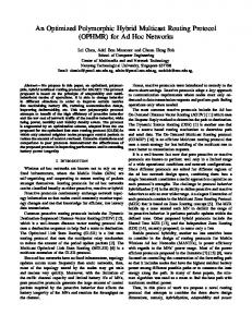
Figure 3. Graphical representation of Table III.
ISSN : 0975-3397
Vol. 9 No.05 May 2017
272
Vinit Kumar Dhull et al. / International Journal on Computer Science and Engineering (IJCSE)
The graph for table III shows that: 1. It is plotted using average data for Experimental model 1, 2, & 3 from table III. 2. The y-axis of the graph is plotted using size column from table III that is in MB’s. This column is for the size of data, which used to transmit over an application for calculation. 3. The x-axis of the graph shows the column average time in a millisecond from table III. This data calculated by taking an average of records for each experimental model from tables II. 4. With the increase in the size of data, the time required for transmission between the web server and the database server increase exponentially for each type of deployment. This graph shows that this change is major for experimental model 3, which shows the geographically distributed cloud deployment.
Figure 4. Communication time difference between experimental models.
The graph in figure 5 shows that gain in communication time between the experimental model 3 and 1 is largest for all sizes of data. For different packet sizes of data, the difference in communication time between tiers for the deployment of the application in the geographically distributed hybrid cloud and private cloud is largest. Thus, by deploying the application according to experimental model 1 will give the most gain in time. By using the formula for one-way transmission C (N-1) from section IV we can see that experimental model 1 is more efficient in term of communication time. Table IV. Percentage gain (in seconds) by experimental model 1 over model 2 and model 3.
Model 1 over Model 3 Model 1 over Model 2
5 0.650 % 0.085 %
10 1.286 % 0.110 %
20 2.313 % 0.151 %
50 6.297 % 0.179 %
100 13.134 % 0.293 %
200 25.125 % 0.493 %
512 56.510 % 0.321 %
In table IV gain of one way communication time in seconds of experimental model 1 is much more in the hybrid cloud which is implemented by experimental model 3 remember this is only one way gain and only between one layer overall gain can be calculated by using the formula 3 from section iv. VI. METHODOLOGY From the data collected by research shows that a significant amount of time taken by request in order to complete a process on a cloud in multi-tier applications where there is a geographical distribution. This is quite applicable in the Intercloud and hybrid cloud. It also observed that there are different results for different types of deployment models in the cloud. The graphs plotted for table III shows the difference between the time for deployment models described in section III with fig 3, 4, and 5. Gains and limitations discussed below:
ISSN : 0975-3397
Vol. 9 No.05 May 2017
273
Vinit Kumar Dhull et al. / International Journal on Computer Science and Engineering (IJCSE)
The merged clusters may have less performing nodes in terms of processing ability to serve a number of hits, as the nodes in the merged cluster move from specialized task to generalized task. The performance degradation would typically depend on the nature of clusters needed to merge. For example, if two clusters are merged which are having underutilized nodes as, for example, in the case Active-directory cluster where the sole purpose of the existence of the cluster is to take care of failover, the degradation would be negligible with better utilization of the resource. In the case of merging of two clusters with a heavy processing, the load may lead to major performance degradation is not advised. Such merging could be a tradeoff between processing delay and communication delay. Adding more nodes to the cluster may compliment the processing delays. Adding up new nodes with small capability is in line with incremental scalability. Furthermore, the merging strategies selected wisely between a more CPU intrinsic cluster and more memory intrinsic clusters to keep the balance. A typical example of a memory intrinsic cluster is a cache cluster, whereas a DAO cluster could mean high CPU utilization if the application has a major focus and activities like reporting that needs not only multiple query fire but also much of frequent result-set traversals. However, the calculation of processing capability loss, which is a trade off for a gain of network communication gain, depends on types of merging and is a subject of future work. It is not necessary to straightforward merge all the cluster and makes a do-all-node cluster. In fact, in a single deployment architecture, there could be more than one merging possibilities for a multi-tier distributed architecture. That is a movement from specialized nodes and clusters to more generalized nodes and clusters are the key essence. However, the merging decision needs to chose wisely depending upon the nature of the tiers and is not a solution that could fit all cases. The evaluation of such dependencies is subject to future work. Data collected in the research is for the only time taken between two tiers of the multi-tier application. This time increased if the application divided into more tiers and will affect the application more in terms of performance. Thus, it‘s concluded that the deployment model described in Figure 2 (a) is the most efficient of all in terms of time taken for a request from one tier to another. By deploying all tiers of multi-tiered web applications on one server in cloud improves performance in terms of communication time between layers. Analysis of this paper can help in determining the criteria for creating clusters of servers based on time lapse due to communication between different layers of the multi-tier application. Especially in the hybrid cloud, it is useful for determining which type of deployment is efficient for the application. Further research scope of research is to determine the efficient ways for cluster creation for N-tier of applications. REFERENCES [1] [2] [3] [4] [5] [6] [7] [8] [9] [10] [11] [12] [13] [14] [15] [16] [17] [18] [19] [20] [21]
Q. F. Hassan, “Demystifying Cloud Security,” CrossTalk, pp. 16–21, 2011. NIST, “NIST Definition of Cloud Computing,” The National Institute of Standards and Technology (NIST), 2016. [Online]. Available: http://www.nist.gov/itl/cloud/. M. Rouse, “What is public cloud? - Definition from WhatIs.com,” TechTarget. 2009. G. A. Lewis, “Role of standards in cloud-computing interoperability,” in Proceedings of the Annual Hawaii International Conference on System Sciences, 2013, pp. 1652–1661. W. Lloyd, S. Pallickara, O. David, J. Lyon, M. Arabi, and K. Rojas, “Performance modeling to support multi-tier application deployment to infrastructure-as-a-service clouds,” in Proceedings - 2012 IEEE/ACM 5th International Conference on Utility and Cloud Computing, UCC 2012, 2012, pp. 73–80. R. Han, M. M. Ghanem, L. Guo, Y. Guo, and M. Osmond, “Enabling cost-aware and adaptive elasticity of multi-tier cloud applications,” Futur. Gener. Comput. Syst., vol. 32, no. 1, pp. 82–98, 2014. L. Cloud Strategy Partners, “Cloud Service and Deployment Models,” pp. 1–15, 2016. D. Bernstein, E. Ludvigson, K. Sankar, S. Diamond, and M. Morrow, “Blueprint for the intercloud - Protocols and formats for cloud computing interoperability,” Proc. 2009 4th Int. Conf. Internet Web Appl. Serv. ICIW 2009, vol. on, pp. 328–336, 2009. T. Kurze, M. Klems, D. Bermbach, A. Lenk, S. Tai, and M. Kunze, “Cloud Federation,” CLOUD Comput. 2011, Second Int. Conf. Cloud Comput. GRIDs, Virtualization, no. c, pp. 32–38, 2011. N. Grozev and R. Buyya, “Inter-Cloud architectures and application brokering: Taxonomy and survey,” Softw. - Pract. Exp., vol. 44, no. 3, pp. 369–390, 2014. W. W. Eckerson, “Three Tier Client/Server Architecture: Achieving Scalability, Performance, and Efficiency in Client Server Applications,” Open Inf. Syst., vol. 3, no. 20, pp. 46–50, 1995. A. Papaioannou and K. Magoutis, “An architecture for evaluating distributed application deployments in Multi-Clouds,” in Proceedings of the International Conference on Cloud Computing Technology and Science, CloudCom, 2013, vol. 1, pp. 547–554. W. Lloyd, S. Pallickara, O. David, J. Lyon, M. Arabi, and K. Rojas, “Performance implications of multi-tier application deployments on Infrastructure-as-a-Service clouds: Towards performance modeling,” Future Generation Computer Systems, 2013. R. Hirschfeld, “Three-tier distribution architecture,” Pattern Lang. Programs, pp. 1–4, 1996. H. S. Oluwatosin, “Client-Server Model,” IOSR J. Comput. Eng. Ver. IX, vol. 16, no. 1, pp. 2278–8727, 2014. O. Corporation, “Oracle Fusion Middleware Administering Clusters for Oracle WebLogic Server.” . S. White, A. Alves, and D. Rorke, “WebLogic event server: a lightweight, modular application server for event processing,” in Proceedings of the second international conference on Distributed event-based systems, 2008, pp. 193–200. Shalini and Syed Imtiyaz Hassan, “An empirical evaluation of the impact of aspectization of cross-cutting concerns in a Smart-Phone based application,” in 2014 International Conference on Computing for Sustainable Global Development, INDIACom 2014, 2014, pp. 448–454. Syed Imtiyaz Hassan, “Modularizing the Cross cutting Concerns Trough Aspect-,” vol. 2, no. 2, pp. 113–118, 2009. J. M. Gallaugher and S. C. Ramanathan, “Choosing a Client/Server Architecture,” Inf. Syst. Manag., vol. 13, no. 2, pp. 7–13, 1996. M. A. AlZain, E. Pardede, B. Soh, and J. A. Thom, “Cloud computing security: From single to multi-clouds,” in Proceedings of the Annual Hawaii International Conference on System Sciences, 2011, pp. 5490–5499.
ISSN : 0975-3397
Vol. 9 No.05 May 2017
274