Keywords: Reversible Logic, Delay, Garbage Output, Flip-Flop, Quantum Cost. I. INTRODUCTION. Energy dissipation in modern circuit design is rapidly.
ISSN (Online) 2278-1021 ISSN (Print) 2319 5940
International Journal of Advanced Research in Computer and Communication Engineering Vol. 4, Issue 8, August 2015
An Optimized Design of Counter Using Reversible Logic Md. Mizanur Rahman1, Indrani Mandal2, Md. Selim Al Mamun3 M.S. Student, Computer Science and Engineering, Jatiya Kabi Kazi Nazrul Islam University, Bangladesh 1 Assistant Professor, Computer Science and Engineering, Jatiya Kabi Kazi Nazrul Islam University, Bangladesh 2, 3 Abstract: Reversible computing has been gaining a great deal of attention from researchers because of its low power consumption. A good amount of research work has been carried out in the area of reversible combinational logic as well as sequential design of reversible circuits. In this paper we proposed efficient designs for both the asynchronous and synchronous counter circuits that are optimized in terms of quantum cost, delay and the number of garbage outputs. Keywords: Reversible Logic, Delay, Garbage Output, Flip-Flop, Quantum Cost. I. INTRODUCTION Energy dissipation in modern circuit design is rapidly becoming a primary design concern. According to Landauer’s the amount of energy dissipated for every Reversible irreversible bit operation is KT ln2 joules of heat energy, Gate where K is the Boltzmann’s constant (1.3807× ) and T is the operating temperature [1]. At room temperature (300 K), KT ln2 is approximately 2.9× J, which is small but not negligible in complete system. This heat dissipation dramatically reduces the performance Fig.1. A n*n Reversible gate and lifetime of the circuits. In 1973 C.H. Bennett showed that KTln2 energy dissipation can be avoided, if a B. Quantum Cost computation is carried out in a reversible way, since this energy dissipation occur when a bit of information is Complex reversible gate are realized by using 1*1 NOT gate and 2*2 reversible gate and the quantum cost of these discarded during computation [2]. complex gate is calculated as the number of 1*1 and 2*2 Researchers introduced several design of reversible reversible gate. Each 1*1 and 2*2 reversible gate is sequential circuits and work is still going on. Researchers considered as unit for measuring overall quantum cost [4]. [12-16] proposed the implementation of all types of The quantum cost of Peres gate is 4 in Fig. 6. latches, flip-flops and their master-slave design. This paper proposes a novel concept on reversible C. Garbage Output asynchronous and synchronous counters using T flip-flop. Garbage output is defined as the outputs that are not The rest of the paper is organized as follows: Section II primary output or output that are not used as input to other provides some basic definitions related to reversible logic. gate. More formally, unwanted or unused or unutilized Section III describes some basic reversible logic gates. outputs which are needed only to maintain reversibility of Section IV presents the design of our proposed reversible a reversible gate (or circuit) is known as garbage output. synchronous and asynchronous counter using proposed T D. Delay flip-flop and its comparison with the existing work. The path which consist maximum number of gates for any Finally Section V concludes the work. input to any output in the circuit is known as critical path. Delay of a reversible circuit is the delay of this critical path. We used Mohammadi and Eshghi [5] proposed logical depth for measuring delay. The delay of each 1*1 and 2*2 reversible gates is taken as unit delay, i.e. 1.
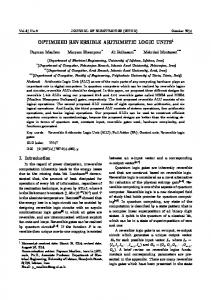
II. BASIC DEFINITIONS A. Reversible Gate A reversible logic gate is an n-input n-output (denoted by n*n) logic circuit in which there is a one-to-one correspondence between its inputs and outputs [3]. If the input vector of the reversible gate is defined as =( , , …. , , ) and the output vector defined as = ( , , …. , , ), then according to the definition, , i.e., it can generate unique output vector from each input vector and vice versa. Copyright to IJARCCE
E. Constant Input The input that is added to a function to make it reversible is called constant input. Input lines are either 0 or 1 should be as minimum as possible. F. Gate Count It refers to the total number of reversible gates used in the designed circuit. But gate count is not a good metric for
DOI 10.17148/IJARCCE.2015.4802
7
ISSN (Online) 2278-1021 ISSN (Print) 2319 5940
International Journal of Advanced Research in Computer and Communication Engineering Vol. 4, Issue 8, August 2015
comparison since each reversible gate is of different computational complexity, and thus will have a different quantum cost and delay [6]. In this paper quantum cost, delay and the number of garbage outputs are used as the cost metrics while comparing the proposed design with the existing designs.
A
P=A
B
Q=
C
R=ABC
III. BASIC REVERSIBLE LOGIC GATES
Fig.5. 3*3 Toffoli gate
A. NOT Gate
E. Peres Gate
1*1 NOT gate is the simplest among all the reversible gates where the gate has only one input (A) and one output (P) such that P= . NOT gate is used as an inverter to invert the applied input. The quantum cost of this gate is 1. The NOT gate is shown in Fig. 2.
The input vector and output vector of 3*3 Peres gate (PG) [10] is defined as follows: = (A, B, C) and = (P = A, Q = A B, R = AB C). It is just like a Toffoli gate but without the last Feynman gate from right. Since it requires 2V, 1 and 1 CNOT gate, it has the Quantum cost of 4. The Peres gate is shown in Fig. 6.
A
P= Fig.2. 1*1 NOT gate
B. Feynman Gate Feynman gate (FG) is the only 2-input 2-output (2*2) reversible gate. It is also known as Controlled-NOT (CNOT) gate. The input vector and output vector of 2*2 Feynman gate is defined as = (A, B) and = (P = A, Q=A [7]. The Feynman gate is shown in Fig. 3.
P=A
B
Q=A
C
R=ABC Fig.6. 3*3 Peres gate
IV. PROPOSED REVERSIBLE COUNTER USING T FLIP-FLOP
P=A
A
A
Even though many research has been done in sequential logic circuits, but quantum cost minimization create a vest research area. Fredkin and Toffoli [11] first proposed the Fig.3. 2*2 Feynman gate design of reversible sequential circuits. Recently Positive . Double Feynman Gate Polarity Reed Muller (PPRM) expression is used to design The input vector and output vector of 3*3 Double synchronous counter by Khan [17]. We have a proposal for designing a synchronous and asynchronous counter, in Feynman gate (DFG) is defined as = (A, B, C) and which cost metrics are minimized. To design this counter = (P = A, Q=A R=A cost of Double Feynman gate is 2 [8]. The Double Feynman gate at first we have proposed two design of reversible T flipflop which is the core component of the counter. is shown in Fig. 4.
Q=A
B
A. Proposed clocked T Flip-Flop
A
P=A
B
Q=A
C
R=AC
The characteristic equation of a T flip-flop is = (T Q).C .Q. The same result can also be obtained from simplified equation as = (T · C Q. It can be mapped with the Toffoli gate. Our proposed clocked T flip-flop in Fig. 7 is realized by a Toffoli gate and a Feynman gate. The proposed T flip-flop has quantum cost 6, delay 6 and has the bare minimum of 1 garbage bit.
Fig.4. 3*3 Double Feynman gate D. Toffoli Gate: Toffoli gate (TG) is one of the most popular reversible gates, invented by Tommaso Toffoli. It is also known as the Controlled-Controlled-NOT(C-C-NOT) gate. The input vector and output vector of 3*3 Toffoli gate [9] is defined as = (A, B, C) and = (P = A, Q = B, R = AB C). The quantum cost of Toffoli gate is 5. It requires 2V, 1 and 2 CNOT gates. The Toffoli gate is shown in Fig. 5. Copyright to IJARCCE
T
T
C
g1 Q
Q 0
Fig.7. Proposed reversible T flip-flop
DOI 10.17148/IJARCCE.2015.4802
8
ISSN (Online) 2278-1021 ISSN (Print) 2319 5940
International Journal of Advanced Research in Computer and Communication Engineering Vol. 4, Issue 8, August 2015
The characteristic equation of a T flip-flop can also be B. Proposed Reversible Asynchronous Counter mapped with the Peres gate. Our proposed another clocked In proposed asynchronous counter each flip-flop is T flip-flop is realized by a Peres gate and a Feynman gate connected to a constant input T. The clock input of the in (Fig. 8) with quantum cost 5, delay 5 and garbage bit 1. first flip-flop is connected to the clock line and other three flip-flops use their clock inputs driven by the Q output of the preceding flip-flop in Fig. 9. The flip-flop holding the C C least significant bit receives the incoming count pulse. The g 1 counter is constructed by using 3 Toffoli gates, 1 Peres T gates and some Feynman gates. The resulting quantum cost is 23, delay 23 and garbage output 1. Comparisons Q Q with existing result are given in Table I.
0 Fig.8. Proposed reversible T flip-flop
T g1
C Q 0
0
0
0
Fig.9. Proposed design of reversible 4-bit asynchronous counter Table I. Comparisons of proposed asynchronous counter gate, n Feynman gate and one Peres gate. The quantum with existing design cost of Toffoli gate is 5. So the total quantum cost is 5*(n1) +1*(n) +4 =6n-1, Hence ≥6n-1. 4-bit Cost comparison asynchronous Quantum Delay Garbage C. Proposed Reversible Synchronous Counter counter cost outputs In synchronous counter all flip-flops are clocked at the Proposed 23 23 1 same time by a common clock pulse. Thus all flip-flops Existing[18] 55 55 12 change state simultaneously. In proposed synchronous Improvement in 58.18 58.18 91.66 counter the flip-flop changes its state only when all the (%) w.r.t. [18] preceding flip-flops are in the state Q = 1 shown in Fig. Theorem: To construct n bit asynchronous counter, if g is 10. This 4-bit synchronous counter has quantum cost 32, the total number of gates required to design the counter delay 32 and garbage output 4. Comparisons with existing producing b number of garbage outputs then g≥2n and result are shown in Table II. b=1. Table II. Comparisons of proposed synchronous counter Proof: Each flip-flop consists of two gates; n bit counter with existing design requires n number of flip-flops. No additional gates are required to interconnect each other. So total number of 4-bit synchronous Cost comparison gates required to design the counter is 2n, hence g≥2n. counter Quantum Delay Garbage Similarly, only the first flip-flop produces one garbage cost outputs output. No garbage output produced while interconnection Proposed 32 32 4 among flip-flops. So the total number of garbage out is Existing [17] 35 35 4 fixed 1, hence b=1. Improvement in 8.5 8.5 0 Theorem: The quantum cost of an n bit asynchronous (%) w.r.t. [17] counter is ≥6n-1. Proof: For n=1, only one Peres gate and one Feynman Theorem: To construct n (≥3) bit synchronous counter, if gate is required to construct the counter. The quantum cost g is the total number of gates required to design the of Peres gate is 4 and quantum cost of Feynman gate is 1. counter producing b number of garbage outputs then So the total cost 4+1=5. g≥4n-4 and b≥n. Now for n>1, one Toffoli gate and one Feynman gate is Proof: Each flip-flop consists of two gates; n bit counter required for each flip-flop in the counter except the first requires n number of flip-flops. For n=3, one Toffoli and one which requires one Peres gate instead of Toffoli gate. one Feynman is required to carry out all the outputs to the So for n bit asynchronous counter it needs (n-1) Toffoli next higher positioned flip-flop. Copyright to IJARCCE
DOI 10.17148/IJARCCE.2015.4802
9
ISSN (Online) 2278-1021 ISSN (Print) 2319 5940
International Journal of Advanced Research in Computer and Communication Engineering Vol. 4, Issue 8, August 2015
C g1
T
g3
g2
g4
Q 0
0
0
0
0 0
0
0
Fig. 10. Proposed design of reversible 4-bit synchronous counter [4] D. Michael Miller, Dmitri Maslov, GerhardW. Dueck, A Transformation Based Algorithm for Reversible Logic Synthesis, Annual ACM IEEE Design Automation Conference, Proceedings of the 40th annual Design Automation Conference, Anaheim, CA, USA Pages: 318 – 323. [5] Mohammadi, M. and Eshghi, M, on figures of merit in reversible and quantum logic designs, Quantum Inform. Process. 8, 4, 297–318, 2009. [6] J.E Rice, "A New Look at Reversible Memory Elements", Proceedings International Symposium on Circuits and Systems(ISCAS) 2006, Kos, Greece, May 21-24 ,2006, pp. 243246. [7] Richard P.Feynman, "Quantum mechanical computers," Foundations of Physics, vol. 16, no. 6, pp. 507-531, 1986. [8] Md. Selim Al Mamun and Syed Monowar Hossain. "Design of Reversible Random Access Memory." International Journal of Computer Applications 56.15 (2012): 18-23. [9] Tommaso Toffoli, "Reversible Computing," Automata, Languages and Programming, 7th Colloquium of Lecture Notes in Computer Science, vol. 85, pp. 632-644, 1980. [10] A. Peres, "Reversible Logic and Quantum Computers," Physical Review A, vol. 32, pp. 3266-3276, 1985. [11] Edward Fredkin and Tommaso Toffoli, "Conservative Logic," International Journal of Theoretical Physics, vol. 21, pp. 219-253, 1982. [12] Md. Selim Al Mamun and David Menville, Quantum Cost Optimization for Reversible Sequential Circuit, (IJACSA) International Journal of Advanced Computer Science and V. CONCLUSION Applications, Vol. 4, No. 12, 2013. [13] M.-L. Chuang and C.-Y. Wang, “Synthesis of reversible sequential A novel design of 4-bit synchronous and asynchronous elements,” ACM journal of Engineering Technologies in counter with the help of T flip-flops has been proposed. Computing Systems (JETC). Vol. 3, No.4, 1–19, 2008. Tables I and II demonstrates that the comparison is carried [14] J. E. Rice, An introduction to reversible latches. The Computer journal, Vol. 51, No.6, 700–709. 2008. out for reversible counter circuit is better than the existing Himanshu Thapliyal and Nagarajan Ranganathan, Design of designs in terms of quantum cost, delay and garbage [15] Reversible Sequential Circuits Optimizing Quantum Cost, Delay, outputs. Appropriate theorems and proof are presented to and Garbage Outputs, ACM Journal on Emerging Technologies in clarify the proposed design and establish its efficiency. We Computer Systems, Vol. 6, No. 4, Article 14, Pub. Date: December 2010. believe this optimization can contribute significantly in [16] Siva Kumar Sastry, Hari Shyam Shroff, Sk.Noor Mahammad, V. reversible logic community. Kamakoti", Efficient Building Blocks for Reversible Sequential Circuit Design" 1-4244-0173 9106/$20.00©2006IEEE. [17] Mozammel H A Khan and Marek Perkowski, Synthesis of REFERENCES Reversible Synchronous Counters, 2011 41st IEEE International Symposium on Multiple-Valued Logic, 0195-623X/11 $26.00 © [1] R. Landauer, “Irreversibility and Heat Generation in the 2011 IEEE. Computational Process”, IBM Journal of Research and [18] V.Rajmohan, V.Ranganathan, "Design of counter using reversible Development, 5, pp. 183- 191, 1961. logic" 978-1-4244-8679-3/11/$26.00 ©2011 IEEE. [2] C.H. Bennett, “Logical Reversibility of Computation”, IBM J.Research and Development, pp. 525-532, November 1973. [3] Hafiz Md.Hasan Babu, Md.Rafiqul Islam, Ahsan Raja Choudhary, and Syed Mostahed Ali Choudhary, "Synthesis of full-adder circuit using reversible logic," International Conference on VLSI Design, vol. 17, pp. 757-760, 2004.
So total number of gates required is 3*2+2=8. For n>3, 2n number of gates required for the flip-flops and 2(n-2) number of gates are required to carry out all the lower outputs to the next higher outputs. So the total number of gates required is 2n+2(n-2)=4n-4. Every flip-flop produces only one garbage output. No garbage output produced while interconnection among flip-flops and to carry out outputs to next higher flip-flop. So the total number of garbage out is n, hence b≥n. Theorem: The quantum cost of an n (≥3) bit synchronous counter is ≥11n-12. Proof: For n (≥3) bit synchronous counter it requires n flip-flops. Each flip-flop consists of one Peres gate and one Feynman gate. Additional (n-2) Toffoli gates and (n2) Feynman gates are required to carry out all the outputs to the next higher flip-flop. So it requires n number of Peres gate, (n-2) number of Toffoli gates and n+(n-2) =2n2 number of Feynman gates. Quantum cost of Peres gate is 4, Toffoli gate is 5 and Feynman gate is 1. So total quantum cost = 4*n + 5*(n-2)+1*(2n-2)=11n-12, hence ≥11n-12.
Copyright to IJARCCE
DOI 10.17148/IJARCCE.2015.4802
10