1Senior Lecturer, EEE Department, Amrita Vishwa VidyaPeetham, Coimbatore, India. 2Assistant Professor, EEE Department, Government College of ...
American Journal of Applied Sciences 4 (7): 508-515, 2007 ISSN 1546-9239 © 2007 Science Publications
ANN Based DSPIC Controller for Reactive Power Compensation Jayabarathi. R.a and Devarajan. N.b Senior Lecturer, EEE Department, Amrita Vishwa VidyaPeetham, Coimbatore, India 2 Assistant Professor, EEE Department, Government College of Technology, Coimbatore, India 1
Abstract: In India with a power shortage of about 10% of installed capacity, the transmission and distribution losses are relatively high. One of the reasons for the large loss is the excessive reactive loads on the primary distribution feeder. With the right amount of reactive power compensation, as system load varies, line losses can be considerably reduced. The application of Artificial Neural Network (ANN) is an emerging area where a properly trained ANN can be advantageously used for sufficient amount of reactive power compensation under varying load conditions. This paper describes the methodology adopted for training an ANN network for reactive power compensation without human intervention. The ANN is implemented using a DSPIC 30F2010 (Digital Signal Peripheral Interface Controller) and verified on a simulated laboratory network . The results obtained are satisfactory. Key words: Distribution system, Shunt Capacitors INTRODUCTION
11kV/415V transformer and associated feeders from the primary are the causes of inefficient power distribution.
Electricity is one of the vital and basic inputs necessary for the economic development of a country. The rapid economic development and industrialization of our country has created a critical need for additional power even though, there has been a spectacular growth in power generation, the demand for electrical power outstrips the supply and efforts are being made to augment power supply by creation of new power stations and revamping the existing stations to achieve higher load factor. However, due to several constraints the suppliers are not able to meet the power demand. Today, in India, out of the total electrical energy generated, about 21% is lost, often during peak load the voltage profile goes below the accepted level. One main cause for high transmission and distribution losses is the high percentage of reactive load. The presence of highly inductive loads is detrimental to the power system and an increase of such loads leads to an increase in reactive power demand thus decreasing power factor of the system resulting in higher losses. Also nowadays it is not possible to monitor the voltage fluctuations and the power losses at the far away buses in a long distribution line. Low power factor and lack of information at the base station (33 kV substation) about the health status of the
It is possible to bring down the distribution losses to a 6-8% level in India by reducing the transmission and distribution losses and by using newer technological options in the electrical power distribution sector, which will enable better monitoring and control. Shunt capacitors can be installed in the distribution substations and the feeders for supplying the reactive power, and voltage at various buses can be monitored to change the tap position of the distribution transformers[1, 2]. Thus the voltage can be maintained within certain limits and hence the losses can be reduced to certain extent. In a distribution substation, various quantities (e.g., voltage, current, switch status, temperature etc) can be recorded in the field at the distribution transformers and the feeders. These system quantities can be transmitted on-line to the base station (33kV substation) through a variety of communication media. The media could be either wireless (e.g., radio and pager) or wired (e.g., dial-up telephone, Ethernet etc). NEED FOR REACTIVE POWER COMPENSATION The presence of loads with large requirement for reactive power is detrimental to the power system. It leads to very high increase in the current flow on the power systems and hence contributes to the system losses. Thus supply
Corresponding Author: R.Jayabarathi, Department of Electrical and Electronics, Amrita Vishwa, VidyaPeetham, Ettimadai, Coimbatore-641105, Tel: 0422-2656422
508
Am. J. Applied Sci., 4 (7): 508-515, 2007 VOLTAGE CONTROL METHODS
of additional of unwanted reactive power, as in the case of highly inductive loads, like arc furnace etc. has to be done at the cost of useful power, which not only is uneconomical but also results in the system instability, because of limited capability of generators to supply reactive power. The power transformers get unnecessarily loaded due to high reactive power requirement and net ‘Real Power Availability’ for the system gets reduced. Also this leads to excessive voltage regulation and the consequent low voltage at the extremities of the system. These higher current flows for the same ‘Real Power’ due to large transfer of reactive power can be ameliorated by the introduction of sources of reactive power close to the load. This is described as ‘Reactive Compensation’ and may take the form of dynamic compensation (i.e.) rotating machines, whose excitation can be varied so that the device may either generate or absorb reactive power; or static compensation (i.e.) shunt capacitor banks which are in general, only variable in their application by being switched in or out. The above, largely applies to period of heavy demand when reactive (lagging power factor) loads have maximum impact on the system. At period of light loads, other problems can occur, (i.e.) when there may be insufficient lagging p.f. loads to absorb the reactive power generated by the system particularly with network with a large cable component. This phenomena can lead to excessive system voltages and sometimes, reactive power compensation is required to absorb reactive power at light load conditions. Application of reactive compensation will be beneficial where the p.f. is poor and will be more effective if applied as close to the reactive loads. This would imply compensation at the consumer terminals and on the low voltage (secondary) system.
A power system is said to be well designed only if it gives a good quality reliable supply i.e. the voltage level should be within certain limits (say within ± 10%). When power is supplied to a load through a transmission line keeping sending end voltage constant, the receiving end load voltage undergoes variations depending upon the magnitude of the load and power factor of the load. The higher the load with smaller power factor, the greater is the voltage variation. Thus various methods are adopted for voltage control. a) Shunt capacitors b) Series capacitors c) Synchronous condensers d) Tap-changing transformers e) Autotransformer tap changing f) Booster transformer In this work, shunt capacitors are used for voltage control. ESTIMATION OF POWER LOSSES VOLTAGE ALONG THE FEEDER
AND
The voltage profile of network and losses under different load conditions are estimated by load flow analysis. Load flow solution of the network under steady state condition is subjected to certain inequality constraint under which the system operates. These constraints can be in the form of nodal voltages, the reactive power generation of the generators, the tap settings of a tapchanging under load transformer etc. The load flow solution gives the nodal voltages and phase angles and hence the power injection at all the buses and power flows through inter connecting power channels and used for planning, operation and economic scheduling. A load flow solution of the power system requires mainly the following steps 1. Formulation of the network equations. 2. Suitable mathematical technique for solution of the equations The load flow can be done using Gauss-Seidal and Newton-Raphson methods. The rate of convergence of the GS method is slow, requiring a considerably greater number of iteration to obtain a solution than the NR method. Due to quadratic convergence of bus voltages, in the NR method, high accuracy is obtained only in a few iterations. In addition, the number of iteration for the GS method increases directly as the number of buses of the network, whereas the number of iterations for the NR method remains practically constant, independent of the system size. The NR method needs 2-5 iterations to reach an acceptable solution for a large system. In the GS and NR methods, convergence is affected by the choice of the
POWER FACTOR IMPROVEMENT The low power factor is mainly due to the fact that most of the power loads are inductive and therefore, take lagging currents. In order to improve the power factor, some device taking leading power should be connected in parallel with load, which partly or wholly neutralises the lagging reactive component of load current. Improved power factor will reduce kVA demand and this will result in lower tariff since the electricity companies usually charge the user on the basis of their maximum. Lower kVA demand will reduce load current and results in the economical selection of switchgear components and cables. Improved voltage drop and thus lesser voltage fluctuation. The electricity companies would also benefit due to better utilization of their distribution system and make more power available to the users.
509
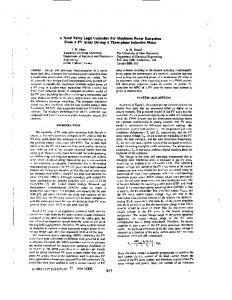
Am. J. Applied Sci., 4 (7): 508-515, 2007 usually the error in the output modified appropriately according to the requirement needed. Both these models will have the three or subgroups of processing elements via, Input layer, Hidden layer, Output layer. The DSPIC family of Digital Signal Controllers (DSC) combines the high performance required in DSP applications with standard micro controller features needed for embedded applications. Pin diagram of DSPIC is shown in Fig.1.
slack bus and the presence of series capacitor, but the sensitivity of NR method is minimal to these factors, which cause poor convergence. Therefore, for large systems, the NR method is faster and more accurate (near exact solution) than the GS or any other known method. In fact, it works variety of ill-conditioned problems. Hence NR method is more reliable than the GS method. ARTIFICIAL NEURAL NETWORKS Artificial neural networks have been widely used in the power industry in fault classification, protection, fault diagnosis, relaying schemes, load forecasting and power generation. At present most ANNs are built upon the environment of real numbers. However it is well known that in computations related to electric power systems, such as load flow analysis and fault level estimation, complex numbers are extensively involved. The reactive power drawn from a substation, the impedance, bus bar voltages and currents are all expressed in complex numbers. But ANNs are able to deal with complex numbers by treating the real parts and imaginary parts independently. ANNs have been proved to be capable of learning from raw data. They can be used to identify relations within raw data not explicitly given or even known by human experts and there is no need to assume any linear relationship between the data. ANNs represent the promising new generation of information processing networks. ANNs can supplement the enormous processing power of the digital computer with the ability to make sensible decisions and to learn by ordinary experience. ANNs have widely been used in electric power engineering. For energy management, load flow and optimum power flow problems are solved by ANNs to estimate bus bar voltages. ANNs can perform the task of associative memory. Since information is stored in the connections and it is distributed throughout, the network can functions as a memory. This memory can work even the presence of certain level of internal noise. ANNs are somewhat fault tolerant in the sense that information is not lost even if some connections are snapped or some units are not functioning. It can deal with data that are not only noisy, but also fuzzy, inconsistent due to associative and distributed nature. They have ability to approximate functions and automatic similarity based generalization. ANNs are distinguished based on the signal flow direction and is classified into, Feed forward network and Feed back network. A feed forward network is a network in which a signal propagates in only one direction from an input stage through intermediate neurons to an output stage. It has no memory since output solely depends on the input. A feed back network is a network in which signal propagate from the output of any neuron to the input of any neuron. What is fed back is
Fig 1: Pin diagram of DSPIC The DSPIC digital signal controllers features In circuit Serial Programming (ICSP) which enables the devices to be programmed after being placed in the circuit board. This offers tremendous flexibility reduces manufacturing cycles and improves time to market. Salient features of DSPIC are following: 1. Bit digital Signal Controller 2. Modified Harvard Architecture 3. C compiler optimized instruction set architecture 4. 84 base instructions 5. Addressing modes 6. 24 bit wide instructions, 16 bit wide data path 7. 12k bytes on-chip flash program spacer 8. 512 bytes on-chip data RAM 9. Two blocks of memory X and Y memory. Both of them has its own independent AGU (Address Generating Units) 10. Sixteen 16 bit working registers. 11. Upto 30MIPS operation 12. Two accumulators ACCA and ACCB – each of 40 bit 13. DSP engine
510
Am. J. Applied Sci., 4 (7): 508-515, 2007 fluctuation. Reactive power compensation by switching is one of the best methods used to minimize the losses and increase the voltage stability. Here, a typical radial distribution feeder is considered and capacitors are connected at various points. A controller is designed based on ANN, to control the ON/OFF positions of capacitors for various percentage loadings. The controller is implemented in hardware using DSPIC 30F2010.
MATHEMATICAL MODELING, SIMULATION AND HARDWARE IMPLEMENTATION The System Studied: The IEEE format of radial type feeder with the eighteen load points originating from 110kV substation is considered. A radial feeder is one that has one supply point and others are load points. This type of feeder is simple and normally used for studies. The normal voltage rating of the feeder is 11,000 V. For the purpose of this work, the radial line is assumed to have no branches.
Table 1: Branch Details of 18 bus radial feeder Feeder Bus No.
1 2 3 4 5 6 7 8 9 10 11 12 13 14 15 16 17
Fig.2: 18 bus radial feeder The details of the system studied i.e., the line resistance, reactance, starting bus, ending bus numbers and 100% loading given in the table 1. The figure 2 gives the single line diagram of the feeder. The table 2 gives the details of feeder in per unit. The capacitors are connected in shunt for compensating reactive power. The location of the capacitors and the reactive power compensated by each of the capacitors is selected for optimal conditions. Here, the capacitors are located at buses 2, 6, 10, 14. The reactive power compensated by these capacitors are 0.2749 p.u, 0.15 p.u, 0.5407 p.u, and 0.1350 p.u. This is obtained by using Genetic Algorithm approach [3-11].
Load (kW)
100.00 90.00 120.00 60.00 60.00 200.00 200.00 60.00 60.00 45.00 60.00 60.00 120.00 60.00 60.00 60.00 90.00
Load (kVAR)
Sta rt
End Bus
R in ohms
X in ohms
60.00 40.00 80.00 30.00 20.00 100.00 100.00 20.00 20.00 30.00 35.00 35.00 80.00 10.00 20.00 20.00 40.00
Bu s 0 1 2 3 4 5 6 7 8 9 10 11 12 13 14 15 16
1 2 3 4 5 6 7 8 9 10 11 12 13 14 15 16 17
0.1844 0.9860 0.7360 0.7622 1.6380 0.3744 1.4228 2.0600 2.0880 0.3932 0.7488 2.9378 1.0032 1.1820 1.4926 2.5780 1.4640
0.0940 0.5022 0.3728 0.3882 1.4140 1.2376 0.4102 1.4800 1.4800 0.1300 0.2476 2.3100 1.4528 1.0520 1.0900 3.4420 1.1480
Table 2: Bus Details of 18 bus distribution feeder
Load Flow Analysis: The load flow analysis is done
Br. No. 1 2 3 4 5 6 7 8 9 10 11 12 13 14 15 16 17 18
from the above details. From this analysis, voltage profile and losses in the system are estimated, from 0.05 p.u to 1 p.u loading at all buses at a power factor of 0.8 without capacitor compensation. The losses were found to be high due to excessive drop in voltage. Hence to improve the voltage, reactive power is injected by installing the capacitors.
Training of ANN: The ANN network is trained with the
data obtained from load flow analysis. The inputs to the ANN are the real power (P), the reactive power (Q), the voltage at the second bus (V2) and the voltage at eighteenth bus (V18). The target is the ON/OFF position of capacitors[12]. The formed ANN network consists of an input layer, two hidden layers and an output layer. The input layer has 4 neurons corresponding to four inputs. The first hidden layer consists of 4 neurons and second hidden layer consists of 20 neurons. The output layer has 4 neurons. The ANN network is trained, and the weights that correspond to minimum MSE (error) is obtained. The loads in the distribution system are inductive in nature and this causes a large amount of current to flow in the line. This causes increase in copper loss and voltage
511
Start Bus 1 2 3 4 5 6 7 8 9 10 11 12 13 14 15 16 17
End Bus 1 2 3 4 5 6 7 8 9 10 11 12 13 14 15 16 17 18
R in p.u. 0.000760 0.00400 0.003040 0.003140 0.003380 0.001540 0.005860 0.008500 0.008620 0.001624 0.003080 0.012140 0.004460 0.004880 0.006160 0.010640 0.006040
X in p.u. 0.000388 0.002080 0.001540 0.001604 0.005840 0.005100 0.001694 0.006120 0.006120 0.000536 0.001024 0.009400 0.005880 0.004340 0.005000 0.014220 0.004740
Am. J. Applied Sci., 4 (7): 508-515, 2007 Table 3: switching status for various loadings LO AD %
P
Q
V2
V17
5 10 15 20 25 30 35 40 45 50 55 60 65 70 75 80 85 90 95 100
0.150 0.301 0.451 0.602 0.752 0.903 1.053 1.204 1.354 1.505 1.655 1.806 1.956 2.107 2.257 2.408 2.558 2.709 2.859 3.010
0.074 0.148 0.222 0.296 0.370 0.444 0.518 0.592 0.666 0.740 0.814 0.888 0.962 1.036 1.110 1.184 1.258 1.332 1.406 1.480
0.9999 0.9997 0.9996 0.9994 0.9993 0.9991 0.9990 0.9988 0.9987 0.9985 0.9983 0.9982 0.9980 0.9979 0.9977 0.9975 0.9974 0.9972 0.9970 0.9968
0.9927 0.9852 0.9776 0.9700 0.9622 0.9544 0.9564 0.9383 0.9301 0.9218 0.9133 0.9047 0.8960 0.8871 0.8780 0.8688 0.8594 0.8498 0.8400 0.8300
Capacitor Switching Status C C C C 1 2 3 4 0 0 0 0 0 0 0 0 0 0 0 0 0 0 1 0 0 0 1 0 1 0 1 0 1 0 1 0 1 0 0 1 1 0 0 1 0 1 0 1 0 1 0 1 0 1 0 1 0 1 0 1 1 0 1 1 0 1 1 1 1 1 1 1 1 1 1 1 1 1 1 1 1 1 1 1 1 1 1 1
Certain capacitors should be switched ON/OFF for different loads. The computation is repeated for all combinations of capacitors installed to find the combination, which gives minimum loss. This is done for all percentage of loadings from 5% to 100% and losses are estimated. From this load flow analysis, capacitor switching for various loading conditions are found and tabulated in the Table 3.
Fig 4: Circuit diagram of DSPIC board The input signals to DSPIC are dc voltages proportional to sending end real power, reactive power, sending end voltage and far-end bus voltage. The dc voltage is at appropriate values compatible with DSPIC. The controller consists of three parts.
Implementation in DSPIC: The DSPIC 30F2010 is chosen.. As it is optimized C compiler, the programs are written in C and compiled using the header file 'p30F2010.h'[13-15] The DSPIC board was made using rectifier and regulator circuits. The output of the regulator is always 5 volts. This is given to DSPIC's VDD i.e., to pins 28,20,13. VSS is connected to ground i.e., maintained at 0 volts (pins 27, 19,8). The oscillator of 20MHz is connected between pin 9 and 10. The circuit diagram of DSPIC board is shown in the figure 4.
1. Analog to digital converter (A/D) 2. The ANN controller 3. Threshold comparator A/D converter: The DSPIC 30F2010 has got inbuilt A/D converter with maximum of 6 inputs from AN0 to AN5. It is a 10-bit high-speed converter. There are six registers that control the operation of ADC. The configurations of these registers are as follows. ADCON1 - A/D control register 1 ADON bit controls the ON/OFF of ADC. The data output format selected is integer. Also the internal counter is used for sampling and conversion. So SSRC is 111. SIMSAM bit is not applicable since only one channel is used here. ADCON2 - A/D control register 2 The reference inputs selected are VDD and VSS. Here, the inputs are scanned. So CSCNA is configured as1. Only one channel i.e., CH0 is utilized so CHPS is 00.Sample/convert sequences per interrupt selection bits
Fig. 3: Schematic Diagram of DSPIC controller
512
Am. J. Applied Sci., 4 (7): 508-515, 2007 matrix is 4X4. The input matrix is 1X4. [1X4] X [4X4] = [1X4] For the first layer, y1 = x1w11+x2w21+x3w31+x4w41 y2 = x1w12+x2w22+x3w32+x4w42 y3 = x1w13+x2w23+x3w33+x4w43 y4 = x1w14+x2w24+x3w34+x4w44 x1,x2,x3,x4 = inputs ( P,Q,V2,V18) y1,y2,y3,y4 = outputs of I layer
(SMPI ) are selected as 0011 as we need interrupt at the completion of conversion of 4th sample/convert sequence. BUFM (Buffer mode selection bit) is 0 as buffer is configured as one 16-word buffer. ALTS = 0 because always MUX A input multiplexer setting is used. ADCON3 - A/D control register 3 Auto-sample time bits (SAMC ) are selected as 12 TAD. A/D conversion clock select bits (ADCS ) are configured for TCY/2. ADCHS - A/D input select register The CH0SA (channel 0 positive input select for MUX A multiplexer setting bits), CH123SA (channel 1,2,3 positive input select for MUX A multiplexer setting bits), CH123NA (channel 1,2,3 negative input select for MUX A multiplexer setting bits), CH0SB (channel 0 positive input select for MUX B multiplexer setting bits), CH0NB (channel 0 negative input select for MUX B multiplexer setting bits), CH0123SB (channel 1,2,3 positive input select for MUX B multiplexer setting bits), CH0123NB (channel 1,2,3 negative input select for MUX B multiplexer setting bits) are not applicable as these are unused. CH0NA (channel 0 negative input select for MUX A multiplexer setting bits) is selected as 0 as VREF- is selected as CH0's negative input. ADPCFG - A/D port configuration register All the ports are configured as analog input ports. ADCSSL - A/D input scan select register Four channels AN0, AN1, AN2, AN3 are selected for input scan. The registers are configured and ADC is turned ON by making ADON bit of ADCON1 (ADC operating mode bit) as 1 i.e., by setting it. The output of ADC is stored in buffer ADCBUF0 to ADCBUF3. These buffers are read only buffers. The program is fused to the chip using Elnec programmer. The input for ADC is given using DCRPS (DC regulated power supply) connected to potentiometer (pot) of 1k resistance. Initially ADC is configured and the working is checked using PWM. The PWM registers are also configured. The output from buffer i.e., ADCBUF0 is transferred to PDC (output of PWM) then verified. For low values of input the pulse width is low. Finally for high value, maximum pulse width is obtained.
w11 w21 w31 w41
w12 w22 w32 w42
w13 w23 w33 w43
w14 w24 = corresponding w34 weight matrix w44
Similarly for the other layers [1x4 ] [4x4 ] = [1x4 ] - input layer [1x4 ] [4x20] = [1x20] - I hidden layer [1x20] [20x4] = [1x4 ] - II hidden layer
Fig 5: Implemented Neural network diagram So the output of 1st hidden layer is 1X4 size matrix. This is given as input to second layer and so on. The implemented neural network diagram is shown in fig.5. The input is obtained from ADC buffer. The value is taken from ADCBUF0 to ADCBUF3 and placed at the input location of input layer. The matrix multiplication of other layers is done successively. [13-15].
ANN controller: From the weights obtained by training the network, the entire network with 4 layer (input layer, hidden layer1, hidden layer2, output layer) is implemented in dsPIC. The program is written in C. Te program of matrix multiplication in each layer is written. Output of one layer is given an input for the next layer. For example, for the first layer, the weight
(iii). Threshold Comparator For the output obtained from the output layer, proper threshold is fixed for each neuron so that the required output shown in the table 5.3 is satisfied. One of the
513
Am. J. Applied Sci., 4 (7): 508-515, 2007 The Hardware setup of DSPIC Controller is shown in fig.6.
ports of DSPIC is configured as output port. Here, PORTE is configured as output port. This is done by configuring TRISE registers. TRISE is configured as 0X0000 i.e., configuring all pins as output pins. The output of the four comparators is sent through ports RE0, RE1, RE2, and RE3. RE0 corresponds to C1. RE1 corresponds to C2. RE2 corresponds to C3. RE3 corresponds to C4. The output is seen at the pins 23,24,25,26. The output is shown by the glowing of LEDs connected to this pins. (iv) Switching of Capacitors during Fault Condition Sometimes, the capacitors may fail to switch on due to some fault condition. There are three possible conditions for occurring fault. The signals transmitted from the controller have not reached the buses properly due to some transmission error. There may be some fault in the switching circuit connected to the capacitors. If the capacitor is open circuited, the controller designed here is adapting itself to the fault condition. The fifth input of the ADC is given as error signal if there occurs fault. The table 4 shows the range of voltage for which it indicates fault in particular capacitor.
Fig. 6: Hardware Set up of DSPIC controller CONCLUSION A radial feeder originating from a substation having eighteen distribution load points is selected for this project. The radial feeder has no branch lines and it is supplied from transformer installed at the substation. To simplify the calculations the following assumptions are made. (i) The power factor of the load is assumed to be constant at all levels. (Various loading conditions) (ii) The real and the reactive power at the various nodes and the injected reactive power by the capacitor are independent of voltage variations. The capacitors that are to be connected for various loading conditions to compensate the reactive power was already obtained from the Newton-Raphson method of load flow analysis. The data obtained are used to train the ANN so that ANN will give output 0 or 1 for each of four capacitors indicating which capacitor is to be connected or disconnected when load changes so that losses are minimum and the weights are obtained. Using the weights the entire ANN network is implemented in the DSPIC 30F2010 along with Analog to Digital converter. For the various values of inputs (i.e., P, Q, V2 and V18) the output was obtained. The output is shown by the glowing of LEDs. The capacitors are also controlled in such a way that if any of the capacitor failed to switch ON due to fault condition, the adjacent capacitor is switched ON to compensate the reactive power.
Here the PORTD is configured as output port. One LED is connected to the RD0 of this port. Glowing of this LED indicates that there is some fault in the capacitors and alarm the operator. If this LED indicates fault, then the capacitors are checked for the fault condition. The nearest capacitor adjacent to the faulted capacitor is switched ON to compensate the reactive power to the maximum extent, although not till the optimum condition. If there are two adjacent capacitors then the capacitor, which can inject the maximum reactive power close to the faulted capacitor, is switched ON. For example consider 50% loading condition, here the switching status of capacitors are 0101. If there occurs some fault in the second capacitor then the switching status is changed to 1001 i.e., the first capacitor is switched ON to compensate the reactive power and to minimize the loss. This is only the temporary solution. So user is alarmed to make required change. Table 4: Voltage range to indicate fault on a particular capacitor
Voltage Range to indicate Fault in Particular Capacitor Voltage range Capacitor 1-1.5 C1 2-2.5 C2 3-3.5 C3 4-4.5 C4
REFERENCES 1.
514
Kishore .A, Hill. E.F., 1971. Static optimization of reactive power sources by use of sensitivity parameters, IEEE Transactions on power apparatus and systems: 1166-1173
Am. J. Applied Sci., 4 (7): 508-515, 2007 2.
3.
4.
5. 6.
7. 8.
Tripathi. K, Martinez .C.A, Nirenberg. S.,1985. A reactive switching simulation in security analysis at Florida Power and Light System control center, IEEE transactions on Power apparatus and systems: 104: .3482-3485 Yuan- Yin Hsu, Feng- Chang Lu, 1998. A Combined Artificial Neural- Network – Fuzzy Dynamic Programming Approach to Reactive Power / Voltage Control in a distribution substation, IEEE Transactions on Power Systems, 13 (4) Grainger J. J., Lee S. H.,1981.Optimum Size and Location of Shunt Capacitors for reduction of Losses in Distribution Feeders, IEEE Trans. On Power apparatus and systems: 1105- 1118. Michalewicz Zbignew, 1994. Genetic Algorithms+Data structures+Evolution Programs,Springer –Verlag Berlin HeidelBerg. Po-Hung Chen and Hong-Chan Chang, 1996. Genetic scheduling of hydraulically coupled plants in hydrothermal co-ordination, IEEE transactions on power systems, 11(2). Kazarlis.S.A., Bakirtzis.A.G, Petridis.V, A Genetic algorithm solution to the Unit Commitment problem, Proceedings IEEE, 42(6): 569-575. David.C.Walters, Gerald.B.Sheble,1993.Genetic Algorithm Solution Of Economic Dispatch with valve point loading, IEEE Transactions on Power Systems, 8(3)
9. 10.
11.
12.
13. 14.
15.
515
Yoshikazu Fukuyama, Hsaio-Dong-Chiang ,1996. A parallel GA for generation expansion planning, IEEE Transactions on power systems, 11(2). Koichi Nara, Atushi Shiose, Minoru Kitagawa, Toshihisa Ishihara, 1992. Implementation of Genetic Algorithm for Distribution Systems loss Minimum Re Configuration, IEEE Transactions on power systems, 7(3). T..Ghose.S.K.Goswami and S.K.Basu,1998.Genetic Algorithm based solution of capacitor placement problem in distribution systems, Institution of Electrical and Electronics Engineers(India.):427-429. R.Jayabarathi,Umasyamkumar,M.R.Sindhu and T.N.P.Nambiar, 2005.Reactive power compensation and voltage control in radial feeders-Using Artificial Neural Networks based controllers, International Conference on Emerging Technologies in Intelligent System and control. DSPIC 30F2010 Datasheet, Microchip Technology. Baran.M.E.,Wu.F.F, 1989.Network reconfiguration is distribution systems for loss reduction and load balancing; IEEE Transaction on power delivery ,4(2):1401-1407. DSPIC Family Reference Manual, Microchip Technology