17 pages
Haskell as a Controller for Reactive Components Barry Norton
1,2
Department of Computer Science University of Sheffield Sheffield, England
Abstract Component-based development is intended to aid the rapid development of applications, as far as possible, via assembly of re-used parts. It has been suggested that Haskell is well suited to the definition of systems in this way. The major use presented for Haskell’s H/Direct interface to Microsoft COM has been the co-ordination of tasks via the Automation model, i.e. as an Automation controller. We present a different model for components, that allows a clean and intuitive notion of composition, and which accommodates components with a strongly reactive behaviour, i.e. which cannot be arbitrarily driven from outside. We show how the notion of reactive types may be used to describe these components and also to compositionally derive an execution model for them. We show how such models can be built and used in Haskell to form a controller without the need for hand-written control code.
1
Introduction
The promise of Component technology is the definition of programs by ‘assembly’, under a simple and intuitive notion of composition. Along the way, in order for this style of development to provide economic advantages, certain ‘subsystems’ of a given program should, themselves, form reusable components. All too often, however, in the application of popular component models, such as Microsoft’s COM[Bro95] and Sun’s JavaBeans[MS00], a great deal of programming effort is put into the ‘wiring-in’ of components within a program in the host language. Our assertion is that this is often due to the need to accommodate the reactive behaviour of a given component. It is typical to view components as abstract data types and this naturally leads to their characterisation in terms of methods and data-type signatures. In fact 1 2
Supported by EPSRC project ‘RealType’, Grant number GR/M99637 Email:
[email protected]
Norton
this is the purpose of interface definition languages, which are at the core of those component models mentioned. Unfortunately, these say nothing about the issue of control and how this constrains use of the interface. The idea presented here rests on extending the description given to components to include their reactive behaviour. We demonstrate how clocked transition systems may be used to express this description, which we call a reactive type. We then show how these may be combined to give an execution model for asynchronous interaction that — at the same time, and in a compositional manner — fulfils an overall synchronisation scheme. The contribution of the paper is then to show how the process algebraic definitions of these reactive types may be used, in Haskell, to form the basis of a controller for a system assembled from reactive components. Notional composition, at the reactive component level, is represented by a deeply embedded parallel composition, whilst interactions between the actual component instances are represented by generalised function composition within the IO monad, produced alongside the process interactions. Hence this reactive component model can be supported over HaskellDirect, where COM components are driven via a wrapper in terms of the IO monad [FLMPJ99]. The provision for Haskell as an Automation controller[LMH99] is thus extended to the control of reactive components without hand written control structure, which is unnatural in a pure functional language.
2
Reactive Components
The natural notion in Haskell for assembly of behaviour from components is function composition. Other notions of component than higher-order polymorphically-typed functions are supported primarily to interface with behaviour from outside the language. There are two motivations for supporting this. Firstly, it is inescapable that there are software requirements that are difficult or infeasible to deal with wholly in Haskell. Secondly, there are motivations, even where this is the case, to use those features that are characteristic of Haskell within an overall solution. In particular, Leijen et al. nominate: strong typing, parametric polymorphism, overloading, abstraction, parameterisation, correspondence, laziness and monads. Leijen et al. point to the use of Haskell for prototyping systems making use of pre-existing functionality exposed via Automation[LMH99]. Automation exists, as a model built over COM, primarily as a mechanism to expose the functionality of applications so that tasks can be automated by an outside agent. This takes the form of a series of imperatives on the application to carry out subtasks; Automation exposes the possible subtasks as function calls. This model may be summarised, we claim, as one where coarse-grained components are re-used individually — rather than the behaviour of components being ‘brought together under composition — and under outside control — i.e. the use and relative ordering of their services is decided from without. 2
Norton
There are at least two types of component where the Automation model seems a poor fit, in particular since the control of interaction at the interface is inverted: where a component is provided in order that it can harvest new data, which it provides at its interface, and where a component operates in cycles, determined in its own terms, as a relationship between input and output. It is the latter type of component, in particular, which we call a reactive component, in the spirit of Berry and Gonthier’s definition of reactive systems: “[Reactive systems] maintain a permanent interaction with their environment, reacting to inputs coming from this environment by sending outputs to it. . . . The logic of the system. . . decides what computations and what outputs must be generated in reacting to the inputs.”[BG92] In fact, these two types of components fit naturally together and are the basis of several systems for ‘visual programming’, which we shall call SGPR (Signal Graph, Programming and Run-time tools) and which are surveyed in [Sch97]. Notable examples include National Instruments’ LabView[JP97] and Hewlett Packard’s Aligent Vee[Tec] (formerly HP Vee). The components used in SGPR tools have three positive features that we should particularly like to harvest for component-based programming in Haskell. In the first place, there clearly exists a very clean notion of composition, since applications in SGPR tools are defined simply in terms of generalised data flow. A data flow graph, called a signal graph, is defined between instances of components and a generic scheduler is able to bring together their behaviour into an application, generally without the definition of further coordination information. Secondly, the definition of applications in this style does indeed facilitate the extraction of subsystems as reusable components in their own right, the second motivator for component-based development mentioned in our introduction. In general SGPR tools allow the definition of components in terms of a signal graph connecting existing components. The third motivator for examining the reactive components used in SGPR tools is practical, and concerns their primary application domain. Both tools mentioned are concerned with the definition of programs for data capture, signal processing and visualisation. As such, many of the source components, those which capture data to make available at their interface, as described above, are dedicated to one particular hardware device, i.e. an I/O board. There, therefore, exist a wealth of these — thousands, in fact, to cover the many measurement devices on the market — which are primarily wrappers around device drivers and naturally written in C. To go with these, there exist many computation components, i.e. those with the strongly reactive nature discussed above, that encapsulate algorithms for the manipulation of this data. There exist, for instance, a wealth of digital filters as components, as well as, for example, FFT components for the transformation of data. To have a clean model for the reuse, together, of these types of components would hence be invaluable to a Haskell programmer. 3
Norton
3
Clocked Transition Systems
Our guide in formalising a component model, of the nature of those in SGPR tools, is another member of that class, iCONNECT, produced by µEpsilon GmbH in conjunction with the University of Passau[SBF+ 98]. Here the notion of composition is based on asynchronous behaviour, i.e. components primarily carry out their behaviour independently, only synchronising when they need to communicate. In fact, however, data taken from different source components must be treated in a co-ordinated fashion. Furthermore, execution is not continuous and concurrent, but rather must be scheduled in interleaved sections — in general onto a single thread on control on a single processor — from outside. Some form of synchronisation, across composition, is therefore needed. This is achieved, practically, according to maximal progress[HdR89], which can be seen as provision for the so-called ‘synchrony hypothesis’ from Esterel[BG92]. The asynchronous model of interaction stands in contrast, however, to that of the ‘synchronous programming’ approach, surveyed by Halbwachs in [Hal98], and is more general. This survey relates the integration of synchronous and asynchronous aspects as useful, since: “In general only some parts of a complex system can be suitably described in the synchronous model.” The RealType project [Rea], within which this work was carried out, investigates the abstraction of reactive behaviour from iCONNECT components and its expression in terms of clocked transition systems. These extend the labelled transition systems defined by CCS[Mil89] and their means of composition; i.e. in particular, parallel composition is based on an interleaving of asynchronous reaction, with handshake synchronisation on named channels. Hennessy and Regan’s calculus, TPL[HR95], extends CCS with clock transitions, as global synchronisations, in close analogy to the global synchronisation on clocks in the synchronous design style for digital circuits. They semantically relate clock and action transitions under the condition of maximal progress; i.e. clocks are ‘held back’ until reaction is complete. A different extension to CCS is Anderson and Mendler’s PMC, which is based on multiple clocks for synchronisation over different scopes of a system in order to model distribution. The process algebra we use, CSA[CGM97], Calculus for Synchrony and Asynchrony, combines the idea of multiple scoped clocks with the semantic relation that maximal progress imposes between them and action transitions. Hence clocked transition systems with scoping are defined, and their parallel composition has the property of local maximal progress. Formally, the syntax of CSA is defined according to the following BNF: P ::= 0 | x | α.P | P + P | P |P | P [f ] | P \ L | µx. P | bP cσ(P ) | P ↑ σ From the rightmost components of this definition, we see that the syntax of CCS has been extended with two operators, which we call, from left to right, ‘timeout’ and ‘ignore’. The intuition behind timeout is that it 4
Norton
introduces a clock transition, labelled σ to the second state. Ignore is the co-scoping operator; by default all initial actions of a process are in the scope of all clocks. P ↑ σ removes the initial actions of P from the scope of σ. The operational rules, providing for this, define a labelled transition system hP, A ∪ T , −→, P i where P is the set of states, A ∪ T the alphabet, formed from A, the set of actions, and T , the set of clocks, −→ the transition relation, and P the start state. The actions are defined, as usual, in terms of the set, Λ, of names, ranged over by a, b, . . . , Λ, their corresponding co-names, ranged over by a, b, . . . , and the silent action, τ . The transition relation −→ ⊆ P × (A ∪ T ) × P is defined, as standard, by structured operational semantics. To ensure maximal progress the operational rules involve side conditions on initial action sets under the scope of clocks. Iσ (P ) ⊆ I(P ), is the set of initial actions of P under the scope of σ, and is defined according to CCS’ plain initial action set I(P ), with df df the additional definitions: Iσ (bP cσ 0 (Q)) = Iσ (P ), and Iσ (P ↑ σ 0 ) = Iσ (P ), only when σ 6= σ 0 , and otherwise is the empty set. We shall not reproduce the whole structured operational semantics for CSA, here, preferring to present the semantics in the form of our implementation. It is worth, however, examining the definition of parallel composition according to the following rules: a α α a σ σ P → P0 Q → Q0 P → P 0 Q → Q0 P → P 0 Q → Q0 , , , τ ∈ / Iσ (P |Q) α α τ σ P |Q → P 0 |Q P |Q → P |Q0 P |Q → P 0 |Q0 P |Q → P 0 |Q0 Here we see the contrast between synchronisation on named channels, which involves exactly two partners in complementary roles, and synchronisation on clocks, which involves all parties not removed from the scope. The side condition, τ ∈ / Iσ (P |Q) on the final rule, imposes maximal progress, since any clock is pre-empted by reaction, i.e. τ transitions within its scope. In drawing the transition diagrams defined by CSA, it will be useful to show clock scoping information. Although the labelled transition system described above is defined in terms of initial actions under the scope of a clock, we shall prefer to show the set of clocks from which the action is removed on each action transition. The notation we use for this adapts the alternative ‘dynamic ignore’ operator, ↓ , from [L¨ ut97], so that a ↓ {σ, ρ} will be used for an action transition which offers a, without adding this to the initial action sets of either σ or ρ and therefore without adding further possibility that they are stopped by reaction on this channel. This will allow us, also, to elide clock loops, i.e. all clock transitions with the same destination as start state. Furthermore, we shall restrict ourselves to a fixed clock sort, as described below. Where any given clock, in this set, is not present as a transition from a certain state, the presence of a clock loop may be intuited from the absence of any τ -transition that is not detached from that clock. Finally, we shall follow the common practice of distinguishing name from co-names, as actions, not by the presence or absence of an over-bar, but with a ‘!’ versus a ‘?’ suffix, suggestive of output versus input. 5
Norton
Source phase σp
σp
σp
Computation phase
σp
σp
σp
σp
Bounded by maximal progress
Source phase σp
σp
σp
Computation phase
σp
Bounded by maximal progress σp
Source phase
σp
σp σp Computation phase
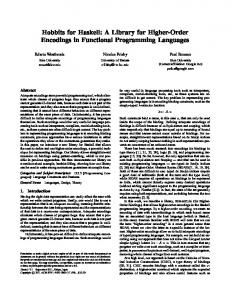
Fig. 1. Phase Synchronisation within Execution Models
4
Execution Models
Our intention is to automatically derive, in the form of a clocked transition system, execution models for functionality built from reactive components. To each component will be assigned, as described in the following section, a model of its reactive behaviour that we shall call a reactive type. Just as instances of the components involved are composed together for execution, we shall compose their types in order to form a model for execution. The family of reactive types that we shall consider are intended to guarantee execution under two execution principles, abstracted from the run-time of iCONNECT. A particular feature of the components that we consider is that there is no centralised mechanism for interaction with the environment; rather there may exist several instances of different ‘source components’, all gathering data from the environment. At the same time, there may exist several ‘computation components’ willing to react to data within the system and possibly produce new such. The first execution principle is that overall execution proceed by alternation between two phases: the source phase and the execution phase, as shown in Figure 1. In the source phase, instances of source components will be given a chance to compute and make available new data. On the tick of a clock which we call the phase clock, ‘σp ’, this phase will end and the computation phase begin. Unlike the source phase, this is an a priori unbounded period of behaviour, since output produced by a given component instance, in reaction to its input, forms the input for other component instances which may, directly or indirectly, include itself. 6
Norton
c1 : Constant Constant
a c3 : Threshold
a b
c2 : Sensor Sensor
T hreshold | F ork2 [a/b1 , d/b2 ]
a d ?
b [b/a]
Fig. 2. Example Application
The second principle for our execution models is that once any component instance becomes ready to carry its internal behaviour, which includes the condition that the composite system is in the right phase, it will wait to be executed and, when signalled to do so, will be allowed to carry out both its internal behaviour and the communication of the results without interruption. Any arbitrary component will be able to control this by holding up a second clock, ‘σe ’, which we call the execution clock, so that no other execution will begin, as well as the phase clock, ‘σp ’, so that the phase cannot end until it is finished. Taking these two principles together, and understanding that both clocks are derived compositionally under the condition of maximal progress, we see as a result all input is gathered from the environment synchronously, and a complete reaction to it computed before new input is considered. As discussed above, we compare this principle to the ‘synchrony hypothesis’ of ESTEREL, even though the reaction here is based on an asynchronous model. Figure 2 shows how we might visualise a system built from reactive components in the dataflow style, with elements of UML[RJB99]. Each ‘wire’ represents one channel in the transition system model. A reactive model is formed for each block from the reactive type of the component it instantiates, changed only via the operations of relabelling and composition with a generic fork component. The reactive types are defined such that an execution model consistent with the two execution principles can then be derived by parallel composition of the model for each block, together with one generic component that converts ticks of the execution clock, ‘σe ’ into execution ‘calls’, ‘e!’. The next section will describe reactive types, using these components as examples. The sections that follow will show how the ‘missing piece’ of this application can be provided by Haskell against a generic controller for the other components, written in C++ and exposed via Microsoft COM. 7
Norton
Sensor τ σe
τ τ
e?
a τ
σp
a!
σp Fig. 3. Source Component Representing a General Sensor
5
Reactive Types
Reactive types have been presented in [Nor01], here we shall consider those for three specific components. Figure 3 shows a diagram that we might use to represent a sensor component, so that its instance may be used in Figure 2. As with all of the models, here, this is defined under the clock sort {σp , σe }, explained in the previous section. Now that we have established which labels the model in Figure 3 will be built from, and their meaning, we shall examine it more closely. The initial state is distinguished as the destination of an arrow without a source. In this, as all models, the initial state represents behaviour within the very first source phase, since the clock ‘σp ’ has not ticked. There are two transitions leaving this state: one is the action ‘e?’, which, as discussed, means that in this state, instances of the component will be ready to execute their behaviour; the other is a busy loop. A busy loop is the name we give to a loop labelled ‘τ ’, and the effect is to hold up all clocks scoped over it until the state is left. In the context of our fixed clock set, this means that the phase clock is held up until the state is left, which can only happen by the request for execution being accepted. The execution clock is not held up, since it is explicitly ignored, i.e. there is a loop on ‘σe ’ back to this state. The effect of the state, therefore, is to insist on being executed within the source phase, but to allow any other instances to be executed first. The following state is left only by the non-deterministic choice between two ‘τ ’ transitions, distinguished by their destination state. Looking ahead, we see that the upper transition meets the destination of the lower via a transition producing output. Hence we see how non-determinism is used to represent data-dependent behaviour. Since neither of the transitions have a set of ignored clocks, we see that both clocks are held up, i.e. that, once their request to execute has been accepted, instances of this component will carry out their internal behaviour to the exclusion of all other components, since ‘σe is held up, and without allowing the end of the phase, since σp is held up. We also see, in the top right hand state, that until the output is communicated, i.e. the ‘a!’ transition followed, the component instance is ‘busy’ to all clocks, i.e. the phase may not end and no other component instance may execute. This is 8
Norton
Constant τ σe
τ τ
e?
a a!
Fig. 4. Source Component for Introducing Constants
Threshold τ σe
a
a? σp σp b?
b
σp
b?
σp a? a?
e? σp b?
a? σp σp a?
σp
c b?
τ
τ
c! a?
τ
Fig. 5. Threshold Component
a general feature of this component model, which we call insistent output, and distinguishes our reactive components from general asynchronous components. Finally, from the bottom right hand state, the ‘execute and output’ behaviour is finished and instances of the component will wait patiently for the end of the phase, signalled by ‘σp ’, allowing an arbitrary number of execution clocks to tick, via the implicit loop, and then wait in the same manner through the following computation phase. At the end of this phase, instances of the component take part in the next source phase in exactly the same way as during the first. Figure 4 shows the model for a considerably simpler source component, which requires to be executed in the first source phase then deterministically, and insistently, produces its single output. Thereafter it has no synchronisation behaviour on actions, and its implicit clock loops in the final state, means it leaves clocks unaffected. This model is useful for components that must deliver a constant value into a composite system, albeit possibly one computed at run-time, for instance from a database. Figure 5 shows the model for a reactive component whose internal behaviour is carried out in the computation phase, and relates together inputs and outputs at its respective ports. In the ‘square’ on the left hand side, we see the input behaviour. Instances of this component start, taking part in the initial source phase, in that state represented in the lower left corner of 9
Norton
the inner square. We see, by inspection, that states in the inner square are related together under exactly the same pattern of observable action transitions as those in the outer square. Furthermore, we see that the only path between the inner and outer squares, and vice versa, is via a single ‘σp ’ transition. Finally, we note that “all roads lead to Rome”, in the sense that action transitions lead us toward the upper right corners of the respective squares, that the only escape is via the outer one of these, and that no resistance is offered to clocks along the way, i.e. there are clock transitions for both clocks at all intermediate states. Hence we understand that instances of the component ‘quietly’ collect their input across as many phases as necessary. From the action transitions involved, we see that exactly one input is collected from port ‘b’, but arbitrarily many more than zero are collected from port ‘a’. We understand that port ‘a’ accepts a threshold value against which the value accepted at port ‘b’ will be compared, when it arrives. Of course, one value is needed for the threshold but, once accepted this may be updated if the value has not arrived. From the state represented at the top right hand corner of the outside square, we see that in this state, reached in the very next computation phase after the input has been collected, we have a busy loop with respect to the phase clock until the execution request is accepted. The pattern of execution and output, represented on the right hand side of the diagram is familiar from the Sensor component — this time we understand that output will be produced only when the threshold is exceeded by the value at ‘b’ — except that we arrive not at the initial state, since we are still in the computation phase, nor even in the phase reached from the initial state after a phase clock, but in a state originally entered when an input on ‘a’ has been accepted. In this way, in non-initial cycles of execution of this component, input at port ‘a’ becomes optional.
6
CSA Interpreter
This section will describe a generic interpreter for the process algebra CSA in Haskell, which can be used to co-ordinate arbitrary I/O actions. The application of this to create a controller for reactive components, based on their types, will be described in the following section. The idea of using a process-based calculus for co-ordination within a functional language is not new. Of particular relevance is the calculus CBS, calculus for broadcasting systems, and its use for co-ordinating distributed systems[Pra95]. From the same group at Chalmers, the working paper [Har95] provides a guide to implementing CCS derived calculi in Haskell against which the current approach is compared. The novelty of this approach lies in being able to automatically derive a process for co-ordination, since all the necessary information about synchronisation responsibilities has been distributed among reusable components via their reactive types. The starting point for an interpreter is a data type for process terms. A 10
Norton
starting point with CCS could be the following, where Name is first defined as some type that instantiates the Eq class: data Process = NIL IN Name Process | OUT Name Process | TAU Process | SUM Process Process | PAR Process Process | REL Process [(Name, Name)] | RES Process [Name] | FIX Variable Process | VARIABLE Variable
This could be interpreted within a context keeping track of process variables to effect a deep embedding of CCS. The approach of [Har95] is to seek a more shallow encoding, where possible, re-using language features from Haskell to achieve the effect of CCS features. Furthermore, their encoding is used for co-ordination by extension to the value passing variant of CCS[Mil89]. Nondeterministic alternative behaviours at each state are presented by a function of the following form, where a is a type parameter for the values being passed within the calculus: step :: Process a -> [Transition a]
Here transitions are merely the pairing of an input or output action or a reaction, i.e. ‘τ ’ actions, and the resultant process. This set of initial actions is finite for any well formed process term, since it has a finite sort. To interpret CSA we must also consider clock transitions. A clock sort, however, is not formed only by a process, but also by its context, so a step function, of the form above and returning a finite list, cannot be constructed, nor would an infinite list, lazily evaluated, be useful. Furthermore it is not possible to construct transitions separately and independently due to the scoping information. Finally, we do not wish to bring the values being communicated up into the calculus; rather the transfer of information should remain implicit. This is particularly motivated by reactive types whose primary goal is to abstract from data and functional behaviour. As discussed in the previous section, there is therefore a need to use non-determinism to specify datadependent choices in reactive types. Clearly this is non-determinism that we wish to resolve, dynamically, according to the component’s state, rather than by arbitrary choice. In fact, we shall allow, for this reason, values to be brought into the calculus, via I/O, but this will be specifically to resolve non-determinism under internal behaviour, i.e. under τ -prefixing, as we shall see. The following, then is the data type we define for CSA processes, having first defined types deriving Eq for Name and Clock: data Process a = NIL | IN Name (Process a) | OUT Name (Process a) | TAU (Process a) | VIN Name (a -> IO()) (Process a) | VOUT Name (IO(a)) (Process a) | VTAU (IO(Int)) [Process a] | TIMEOUT (Process a) Clock (Process a) | IGNORE (Process a) Clock | SUM (Process a) (Process a) | PAR (Process a) (Process a)
We see that action prefixes are duplicated, so that we have one of each just as 11
Norton
before, and a new version that encodes a side effect. We shall call these latter prefixes, and the transitions they result in, ‘effective’. We regard the set of names for standard and effective channels as disjoint and never compare them. We also see that all prefixes, and the new TIMEOUT constructor, via which we introduce explicit clock transitions, lead to fixed processes, except for the effective internal action, VTAU. This encodes a list of possible destination states, and the side effect will nominate one of these once applied. The only operators that we then need as constructors, i.e. which we must deeply encode, are SUM and PAR, i.e. non-deterministic choice and parallel composition. In particular, we shall demonstrate how we can use Haskell features to obviate the need for restriction and renaming and for an explicit constructor for recursively defined processes. In order to interpret processes, we first make the following definitions: type DetachedAction a = (Action a, [Clock]) data Action a = Observable (Label a) (Process a) | Silent (Process a) | IOSilent (IO(Process a)) data Label a = Input Name | Output Name | IOInput Name (a -> IO()) | IOOutput Name (IO(a))
We can then define a function to derive the initial actions and their scoping information, side by side, from a process: scopedActions :: Process a -> [DetachedAction a]
This is defined using pattern matching on the process. A clause for each constructor is defined, using list comprehensions to mirror a set-based expression of the operational semantics. All prefixes simply return a list with the single element a ‘DetachedAction’ built from the appropriate ‘Action’ and an empty set; in other words an action not removed from the scope of any clock. The only interesting clause for prefixes is the following: scopedActions (VTAU f ps) = [(IOSilent (f >>= (\n -> return (ps!!n))), [])]
This shows how the side effect in an ‘effective internal reaction’ prefix will be used to determine the relevant process. The useful clause from the point of view of scopes is the one dealing with the IGNORE constructor — this adds the associated clock to the list of detached ones from the associated process, computed by a recursive call to the function. In terms of actions, summation merely provides a choice between the action transitions of each component, the resulting processes being the same, since the operator, SUM, disappears. This clause therefore combines the lists for each component under concatenation, and is the basis of non-singleton lists returned from the function, representing non-deterministic choice. Finally, a clause for the PAR constructor is made up from a concatenation of list comprehensions representing each of the rules given in Section 3, but for the final one, which concerns only clock transitions. The interesting component, from the point of view of side effects, is made up from the following and its symmetrically defined counterpart, where the parallel components take opposite roles: [(IOSilent (g >>= f >> return (PAR p’ q’)), [detachedClock |
12
Norton detachedClock [Process a] reactionDerivatives :: Process a -> [Process a] vInDerivatives :: Process a -> Name -> [a -> IO(Process a)] vOutDerivatives :: Process a -> Name -> [IO((a, Process a))] vReactionDerivatives :: Process a -> [IO(Process a)] clockDerivative :: Process a -> Clock -> Maybe(Process a)
Hence we see a uniform interaction with processes, for both action and clock transitions, but one of a different nature from the step function discussed above; we provide the clock or name in which we are interested, in order to determine transitions. In this way we remove, obviating the need for restriction on actions and examine a process in the context of any clock sort we wish to impose. While all of the functions concerned with actions may be derived simply by selection from the list returned by the ‘scopedActions’ function, the ’clockDerivative’ function must use the result to decide on the presence of the given clock transition under maximal progress: clockDerivative p sigma = let actions = (scopedActions p) in if null( [() | (Silent p’, detachedClocks) IO(Int) -> Name -> Process a constant aChannel aPort behaviour execute = (IGNORE busy Execution) ‘SUM‘ (IN execute (VTAU behaviour [busy ‘SUM‘ (VOUT aChannel aPort NIL)])) sensor :: Name -> IO(a) -> IO(Int) -> Name -> Process a sensor aChannel aPort behaviour execute = let compute = VTAU behaviour [(busy ‘SUM‘ (VOUT aChannel aPort finish)), finish] finish = nextPhase(nextPhase(sensor aChannel aPort behaviour execute)) in (IGNORE busy Execution) ‘SUM‘ (IN execute compute)
The first point to note is the abstraction from names in these definitions; a deep embedding of renaming via substitution is unneeded as we appropriate Haskell’s function abstraction for the purpose. In fact, we have also abstracted all of the side effects from these types. In defining these processes, we have used auxiliary definitions of processes and process combinators, as follows: nextPhase :: Process a -> Process a nextPhase p = let ignoreExecution = TIMEOUT NIL Execution ignoreExecution in TIMEOUT ignoreExecution Phase p busy :: Process a busy = TAU busy
There is clearly a wealth of useful combinators we can build by abstracting processes from definitions in the form of the first of these. The latter definition shows very clearly how we can use Haskell’s mechanisms to achieve recursive definition without the need for a deeply embedding process substitution mechanism. We can see how ‘sensor’ itself is recursively defined. Another abstraction that we can easily define provides for the family of ‘F orkn ’ components, used to form execution components, as mentioned in Section 4: fork :: Name -> [Name] -> (a -> IO()) -> IO(a) -> Process a fork a bs inPort outPort = VIN a inPort (foldr1 SUM (map (\b -> VOUT b outPort (fork a bs inPort outPort)) bs))
In order to concretise these functions to processes, a user must name their channels, which is done according to the form of the connection desired between each instance, as in Figure 2. The user must also bind the side effects, which is done by instantiating first the corresponding software component. A very useful feature of COM is its definition and implementation in terms of ‘interface pointers’, or references. Rather than binding function calls returning and accepting data to the side effects, which would have the effect of brining all data values into the Haskell controller, we can therefore bind functions that pass references. For the example application, we might define an ‘OutputPort’ interface, willing to provide an integer value, and an ’InputPort’ interface willing to obtain a value from an output port, using COM’s IDL (Interface Definition Language), as follows: interface IOutputPort : IDispatch { [id(1), helpstring("method getValue")] HRESULT getValue([out] int* pValue); };
14
Norton interface IInputPort : IDispatch { [id(1), helpstring("method retrieveValue")] HRESULT retrieve([in] IOutputPort** ppOutput); };
We may then define the ‘Threshold’ component of Figure 5 as: interface IThreshold : IDispatch { [id(1), helpstring("method execute")] HRESULT execute([out] int* pChoice); [id(1), helpstring("method getA")] HRESULT execute([out] IInputPort** ppA); [id(1), helpstring("method getB")] HRESULT execute([out] IOutputPort** ppB); coclass Threshold { [default] interface IThreshold; }; };
From this description of a component, we can obtain, via HaskellDirect[FLMPJ99], Haskell wrappers for the component, giving us the IO functions we need, along with channel names, to instantiate the ‘threshold’ function up to its final abstraction, having instantiated the type parameter of ‘Process’ to the type of an ‘IOutputPort’ interface pointer. Following a similar process for the other two components used in Figure 2, we can produce a process representing the possible execution of this system: foldr1 PAR (map \f -> (f "a") [boundConstant, boundSensor, boundThreshold, (fork "a" ["a", "d"]), [scheduler])
This makes a parallel composition of the instantiated types for the three reused components, a fork and the generic scheduling component, described in Section 4. We can use this to drive the software components directly via the function drive, parameterised on: the effective channels via which we should like to receive output; the clock sort in which we should like to interpret the process; the process describing the current state of the system. We chose to partially evaluate this to be specific to our application. drive :: [Name] -> [Clock] -> Process -> ([(Name, IO((a, Process a)))], [(Clock, Process a)], [IO(Process a)], [Process a]) driveExample = drive ["d"] [Phase, Execution]
For each process we pass to this function, we obtain the tuple defined by ‘drive’, which gives us: a list of pairs describing output that is available in terms of the channel and an IO process that will provide us the output and the new system state; a list of pairs of possible clock transitions in terms of the clock and the new system state; a list of possible effective reactions within the system in terms of a function effecting the reaction and providing the new system state; a list of other reactions possible and the resultant system states. Our strategy is to chose from this non-deterministic ‘menu’ at each step of execution, but with preference for the earlier components of the tuple. In other words, we should like output if possible, if not we are interested to know if the phase has ended, if this is not the case, we should like the system to continue in its effective reaction until either of the earlier conditions are true and finally we are willing to let internal synchronisations within our model to take place. In order to progress the system, having chosen a member of one of the lists, and having applied the IO function to obtain the next process if necessary, we simply pass the resulting process back through drive and so on. 15
Norton
8
Conclusion
We have explained the notion of reactive types and explained how they can be described for a useful class of component in a process algebra defining clocked transition systems. We have shown how, under composition, abstract execution models can be derived. We have then shown a manner in which these models may be directly formed and used, in Haskell, to drive real component instances, and to resolve non-determinism in the model according to their dynamic state. A sizeable case study for this approach is now planned in co-operation with the collaborators on the RealType project, who have a great deal of experience in producing components of the kind discussed.
9
Acknowledgements
I should like to acknowledge the personal support and advice of my PhD supervisor, Michael Mendler, and financial support in employing me as research assistant on the RealType project. I should also like to acknowledge the contribution of collaborators at the University of Passau, in particular Bernhard Sick and Walter Maydl, and at µ-Epsilon GmbH, in particular Roland Mandl and Andreas Bauhofer. The collaboration is supported by the British Council under the Academic Research Collaboration Scheme, Project number PRO1163/CH.
References [BG92] G. Berry and G. Gonthier. The ESTEREL synchronous programming language: Design, semantics, implementation. Science of Computer Programming, 19:87–152, 1992. [Bro95] Kraig Brockschmidt. Inside OLE. Microsoft Press, second edition, 1995. [CGM97] R. Cleaveland, G.L¨ uttgen, and M.Mendler. An algebraic theory of multiple clocks. In Proceedings of CONCUR’97, volume 1102 of LNCS, pages 166–180, 1997. [FLMPJ99] Sigbjorn Finne, Daan Leijen, Erik Meijer, and Simon Peyton Jones. H/direct: A binary foreign language interface for haskell. In Proceedings of International Conference on Functional Programming, ICFP’98, volume 34 of ACM SIGPLAN Notices, pages 153–162, 1999. [Hal98] Nicolas Halbwachs. Synchronous programming of reactive systems. In Computer Aided Verification, pages 1–16, 1998. [Har95] Ed Harcourt. An extensible interpreter for value-passing CCS. http://www.cs.chalmers.se/ ms/PARA/ccspaper.ps, 1995.
16
Norton
[HdR89] J. J. M. Hooman and W. P. de Roever. Design and verification in real-time distributed computing: An introduction to compositional methods. In Proceedings of the Ninth International Conference on Protocol Specification, Testing and Verification, 1989. [HR95] M. Hennessy and T. Regan. A process algebra for timed systems. Information and Computation, 117(2):221–239, March 1995. [JP97] R. Jamal and H. Pichlik. LabVIEW–Programmiersprache der Vierten Generation. Prentice Hall, 1997. [LMH99] Daan Leijen, Erik Meijer, and James Hook. Haskell as an automation controller. In Proceedings of 3rd International Summer School on Advanced Functional Programming, Braga, Portugal, number 1608 in LNCS, 1999. [L¨ ut97] Gerald L¨ uttgen. Pre-emptive Modeling of Concurrent and Distributed Systems. PhD thesis, Fakult¨at Mathematik und Informatik, Universit¨at Passau, November 1997. [Mil89] Robin Milner. Communication and Concurrency. Prentice Hall, 1989. [MS00] Vlada Matena and Beth Stearns. Applying Enterprise JavaBeans: Component-Based Development for the J2EE Platform. AddisonWesley, 2000. [Nor01] Barry Norton. Clocked transition systems and the compositional modelling of reactive components under synchronous scheduling. In Bulletin of the European Association of Theoretical Computer Science (EATCS), number 75. October 2001. Available on-line: http://www.dcs.shef.ac.uk/ barry/BCTCS17/. [Pra95] K. V. S. Prasad. A calculus of broadcasting systems. Computer Programming, 25, 1995.
Science of
[Rea] Realtype project. http://www.dcs.shef.ac.uk/ barry/RealType. [RJB99] J. Rumbaugh, I. Jacobson, and G. Booch. The Unified Modeling Language Reference Manual. Addison-Wesley, 1999. [SBF+ 98] A. Sicheneder, A. Bender, E. Fuchs, M. Mendler, and B. Sick. Tool-supported design and program execution for signal processing applications using modular software components. In T. Margaria and B. Steffen, editors, International Workshop on Software Tools for Technology Transfer STTT’98. Springer, 1998. [Sch97] P. G. Schreier. Users adopt new technologies, return to familiar suppliers. Personal Engineering, pages 22–25, Jan 1997. [Tec] Aligent Technologies. Aligent Vee. http://www.tm.agilent.com.
17