Antenna Design through Space Mapping Optimization. Jiang Zhu, John W. Bandler, Fellow, IEEE, Natalia K. Nikolova, Senior Member, IEEE, and Slawomir ...
1605
Antenna Design through Space Mapping Optimization Jiang Zhu, John W. Bandler, Fellow, IEEE, Natalia K. Nikolova, Senior Member, IEEE, and Slawomir Koziel, Member, IEEE McMaster University, Hamilton, ON, Canada L8S 4K1, www.sos.mcmaster.ca Abstract-For the first time, we apply space mapping to antenna design. We exploit a coarse-mesh method-of-moments (MoM) solver as the coarse model and align it with the fine-mesh MoM solution through implicit space mapping and output space mapping. A novel local meshing method avoids inconsistencies in the coarse model. Our new user-friendly SMF system optimizes the impedance of a patch antenna in four iterations. In a double annular ring antenna the finite ground size effect for the MoM is efficiently solved and the design specification is satisfied after only three iterations. Index Terms-Antenna design, CAD, EM optimization, method of moments, surrogate modeling, space mapping.
I. INTRODUCTION
The method of moments (MoM) is one of the most frequently used numerical techniques for analysis of planar structures. An accurate MoM simulation is cpu intensive. This cost may be prohibitive for complex design problems. Alternatively, a typical coarse mesh MoM simulation is fast, but poor in accuracy. The space mapping (SM) technique takes advantage of the efficiency of a coarse mesh MoM simulation and the accuracy of the fine mesh simulation. SM aligns coarse models with fine models [1]-[3]. Here, the fine model is the fine mesh MoM solution. The coarse model is the coarse mesh solution. For the first time, we apply the SM technique to antenna design. Both fine and coarse models are defined within the commercial EM solver FEKO, which is used primarily for antenna design based on the MoM [4]. We propose a new meshing method: the topology of the mesh is preserved throughout the optimization which makes the coarse-model response in the design parameter space smooth and consistent. In the parameter extraction (PE) process, we implement implicit SM (ISM) and output SM (OSM) sequentially [2], [3]. In a preliminary PE, we roughly align the coarse model with the fine model through ISM. Then OSM aims at locally matching the surrogate with the fine model.
This work was supported in part by the Natural Sciences and Engineering Research Council of Canada under Grants OGP0007239 and STGP269760, and by Bandler Corporation. The authors are with the Simulation Optimization Systems and Computational Electromagnetics Research Laboratories, Department of Electrical and Computer Engineering, McMaster University, Hamilton, ON, Canada L8S 4K1. J.W. Bandler is also with Bandler Corporation, P.O. Box 8083, Dundas, ON, Canada L9H 5E7.
0-7803-9542-5/06/$20.00 C2006 IEEE
Our new SMF system [5] implements our approach. SMF is a GUI-oriented Matlab space-mapping nonlinear optimization software package with sockets to popular EM simulators, including FEKO, Sonnet em and Agilent ADS. We consider a patch antenna and a double annular ring antenna. In the first example, we optimize impedance at a single frequency, and then discuss the coarseness in the coarse model and its effect on the SM performance. In the second example, we exploit the cpu-intensive surface equivalence principle (SEP) as a fine model and the special Green's function with a coarse mesh as a coarse model. The Sparameter response is optimized in 3 iterations. II. MESH CONVERGENCE AND MESHING METHOD
The mesh convergence needs to be checked to get an accurate simulation result. This is done by refining the mesh from one simulation to the next, and keeping all other parameters the same. If the results are significantly different, the surfaces are not adequately discretized and we need to refine the mesh [6]. The coarse-mesh coarse model does not need to achieve mesh convergence. Consequently, the variation of the mesh number and topology due to the variation of geometrical design parameters during optimization leads to inconsistent results. To overcome this problem, we force the mesh number and topology to remain unchanged during optimization. This is done by local meshing in FEKO. In the fine model, where mesh convergence is satisfied, we use global meshing. We define the mesh density by the number of meshes per wavelength. III. SM-BASED SURROGATE MODELS
We are concerned with a class of optimization algorithms that exploit surrogate models [7]. Let Rf: Xf - Rm denote the response vector of the so-called fine model of a given object, where Xf c Rn. Our goal is to solve
Xf = arg min U(Rf (xf )) XfeXf
(1)
where U is a suitable objective function. SM assumes the existence of a less accurate but much faster coarse model. Let RC : X, xXXp - Rm denote the response vectors of the coarse model, where XCCR' is the design
1606 is the variable domain (we assume here that XjzXf) and X domain of auxiliary (preassigned) coarse model parameters. Typical preassigned parameters xp are the dielectric constant and the height of a dielectric layer. By x* we denote the optimal solution of the coarse model, i.e., XC
=
min U(Rc(x,x())) arg X(EXC P
Step 1 Step 2 Step 3 Step 4 Step 5 Step 6
(2)
k1
where x(°) denotes the initial preassigned parameter values. We consider the fine model to be expensive to compute and solving (1) by direct optimization to be impractical. Instead, we use surrogate models, i.e., models that are not as accurate as the fine model but are computationally cheap, hence suitable for iterative optimization. We consider an optimization algorithm that generates a sequence of points x7)e Xf, i=1,2,..., sothat
x( +l) = arg min U(R(') (x)).
IV. EXAMPLES
A. Patch Antenna This patch antenna is printed on a substrate with relative dielectric constant -r = 2.32 and height h = 1.59 mm. The design parameters are the patch length and width, i.e., xf = [L W]T . The objective is to obtain 50 Q input impedance at 2 GHz. The objective function is lZin -501. In the fine model, the global mesh density is 30 meshes per wavelength. In the coarse model, the mesh number and topology are fixed through local meshing. We choose three mesh edges along L and seven along W. See Fig. 2. Our selected preassigned SM parameter is x = r . In the PE, we match the complex SI, instead of the input impedance. The initial design point is the coarse model optimal solution (°)=[47.1285 100.470]mm. The SMF system requires 5 iterations (6 fine model simulations). Fig. 3 shows the reduction of the objective function versus the number of the iterations. The final design is x; = (4) = [46.7294 99.6875] mm. Table I shows the optimization results for the design parameters, the objective function value, the preassigned parameter and the output SM parameter at each iteration. Computation time is 341 seconds, compared with 2816 seconds for direct fine model optimization. Table II discusses the effect on the SM performance of the coarseness of the coarse model for the patch antenna. The algorithm does not converge for 24 meshes. With increase of the number of meshes, the function evaluation time increases while SM iterations decrease. We have the best SM performance in terms of total time cost for 100 meshes, which requires only 341 seconds.
(3)
Here, R(') : Xc -> Rm is the surrogate model at iteration i, which uses the coarse model and the fine model data. In this work, we use a surrogate model based on implicit SM [2] and output SM [3]. The surrogate model at iteration i is defined as
R(i) (x) = RC (x, xpi)) +AR(').
(4)
xp 0) = arg min Rf (x))- RC (xI),x)
(5)
AR(i) = Rf (x(i))-R(x(i),x)).
(6)
where
and Both implicit and output SM aim at reducing the misalignment between the fine model and the current surrogate, however ISM exploits the physics-based similarity of the models, while the OSM ensures perfect local alignment between the models at the current iteration point. As follows from equations (4)-(6), we implement ISM and OSM sequentially. This is illustrated in Fig. 1. design
parameters
~~
Xf
Choose a proper coarse-mesh coarse model as well as preassigned parameters. Set i = 0. Solve (2) to find the surrogate optimal solution x* and let Xf0) = x*. Evaluate the fine model to find R1 (xf)). Update the surrogate model R(') according to (4)-(6). Solve (3) and obtain xf+). f If the termination condition is satisfied (convergence achieved or the design specification satisfied), stop; otherwise, set i = +1± and go to Step 3.
responses
xD Sdmodel iRXf
L
surrogate
implicit Imapming ^^ I ; X-
|
mapping
coarse mde
sc
output ~~~~~~~mapping
Rc
i
responses
L. P
Fig. 1.
preassigned parameters
AR
Demonstration of our approach to implicit and output SM.
Fig. 2.
(a)
(b)
Demonstration of coarse model and fine model. (a) Coarse model with three mesh edges along L and seven mesh edges along W. (b) Fine model with global mesh density of 30 meshes per
We implement the SMF system [5] as follows.
wavelength.
2
1607 30r
_ Y
(Pp, ob)
6-
d2
0
1
2
3
4
r2:
a2
Iteration Number
Fig. 3. Objective function value versus iteration number in the microstrip patch antenna example.
al
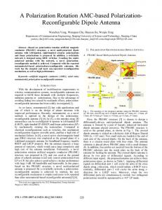
Fig. 4. Geometry of a stacked probe-fed printed double annular ring antenna example.
TABLE I OPTIMIZATION RESULTS FOR THE PATCH ANTENNA EXAMPLE AR Iteration |Zin -50 Er Xf (mm)
0 1 2
3 4
F47.1285 100.470
2.3200
F46.777431008 1 2.3621 L99.6922 F46.72681 99.6960 2.3589 46.72941 99.6883
27.941
.41 0.0082 0.0461i
2.5616
Fig. 5.
0.0145 + 0.0056i
0.35956
ring antenna example.
2.3590
0.0118+0.0054i
2.3589
0.0115+0.0059i 1.1234x10 2
F46.72941 99.6875
0.0000
Demonstration of local meshing of the annular ring in the coarse-mesh coarse model for a stacked probe-fed printed double
The finite ground size is 100 xlI 00 mm. The radius of the feed pin is ro = 0.325 mm. Design variables are the outer and inner radius of each ring and the feed position, namely, [a, a2 b1 52 'p~]T The design specification is .-1OdB for1.75GHz.w.2.15GHz.
2.4437x10⁻²
IS11
In an MoM solver like FEKO, special Green's functions are usually implemented to model multi-layer substrates, where the ground and the substrate are assumed infinite in extent. It is computer-resource efficient, since only the finite metallic surfaces are discretized. However, in many microwave and RF applications, the infinite ground plane assumption is not acceptable for accurate simulations. The ground size has a strong effect on the performance of microstrip antennas. The surface equivalence principle (SEP) addresses this problem. The surface of a dielectric is discretized for the electric and magnetic currents on the surface. All sides of a dielectric have to be meshed, making a closed solid. In this approach, the memory requirement is four times what it would be if the same structure was metallic [9]. We choose the SEP model as the fine model and the special Green's function, which does not consider the finite ground size effect, as the coarse model. To further reduce the simulation time in the coarse model, we apply a coarser mesh by local meshing. As shown in Fig. 5, the number of mesh edges along the three loops (thick lines) is topologically fixed at 5, 10 and 15, respectively, regardless of the variation in the design parameter values. The detailed fine and coarse models are shown in Table III.
TABLE II THE EFFECT OF LOCAL MESHING ON SM PERFORMANCE FOR THE PATCH ANTENNA SM performance Local meshing in the coarse model Mesh number along Total mesh Function Iteration Total time evaluation IeainTtltm number (s) L time (s) number w 2 24 5 0.109 Not convergent 6 3 7 48 0.219 364 4 341 5 9 100 0.438 4 9 20 400 4.063 1604 11 22 3 528 8.375 2695 Global meshing in the fine model Direct optimization 0 Mesh density=30 1032* 33.313* 2816 * The number of meshes and function evaluation time in the fine model is measured at the starting point [L W] = [55 85] mm
B. Double Annular Ring Antenna We consider the stacked probe-fed printed annular ring antenna of [8] which is shown in Fig. 4. The antenna is printed on a PCB with I = 2.2, d1 = 6.096 mm for the lower substrate and 8r2 = 1.07, d2 = 8.0 mm for the upper substrate. The dielectric loss tangent is 0.001 for both layers.
3
1608 TABLE III FINE MODEL AND COARSE MODEL IN DOUBLE ANNULAR RING ANTENNA Model ..Mesh Frequency Technique Meshing method number sweep type time Coarse Special Green's function + Local meshing 83 8.721 seconds model coarse mesh Fine SEP Global meshing 2661* 1 hour and 18 model density =20 minutes * Number of meshes and time cost in fine the model are measured at the initial point
0.35r
0.05
e
final fine response
i
-
X---- final surrogate response
1.75
1.85
1.95 Frequency [GHz]
2.05
2.15
Fig. 7. Final fine and surrogate responses for the double annular ring antenna example. TABLE IV INITIAL AND FINAL DESIGN OF THE DOUBLE ANNULAR RING ANTENNA Design Initial design Final design (mm) (mm) parameters 9.2277 10.6735 a1 8.7224 7.8088 a2
b,
0 1.75
b2 1.8
1.85
1.9
2 1.95 Frequency [GHz]
2.05
2.1
pp
2.15
Fig. 6.
Initial fine and surrogate responses corresponding to the coarse model optimal solution for the double annular ring antenna.
30.7230
28.4621
34.1266 18.2107
32.5043 19.6817
Dr. A.S. Mohamed and W. Yu of McMaster University for insightful comments.
The SMF system needs 3 iterations (4 fine simulations) to
REFERENCES
satisfy the specifications, although the coarse model initially
exhibits a poor response [see Fig. 6]. The total time taken is 5 hours 58 minutes (a single fine model simulation requires 1 hour 18 minutes). Fig. 7 depicts the fine and surrogate model responses at the final design. Good alignment is achieved with three PEs. Table IV shows the initial and final design.
[1] J.W. Bandler, R.M. Bienacki, S.H. Chen, P.A. Grobelny and R.H. Hemmers, "Space mapping technique for electromagnetic optimization," IEEE Trans. Microwave Theory Tech., vol. 42, pp. 2536-2544, Dec. 1994. [2] J.W. Bandler, Q.S. Cheng, N.K. Nikolova and M. A. Ismail, "Implicit space mapping optimization exploiting preassigned parameters," IEEE Trans. Microwave Theory Tech., vol. 52, pp. 378-385, Jan. 2004. [3] J.W. Bandler, Q.S. Cheng, D. Gebre-Mariam, K. Madsen, F. Pedersen and J. S0ndergaard, "EM-based surrogate modeling and design exploiting implicit, frequency and output space mappings," in IEEE MTT-S IMS Dig., June 2003, pp. 1003-1006. [4] FEKO® User's Manual, Suite 4.2, June 2004, EM Software & Systems-S.A. (Pty) Ltd, 32 Techno Lane, Technopark, Stellenbosch, 7600, South Africa, http:Hwww.feko.info. [5] SMF, Bandler Corporation, P.O. Box 8083, Dundas, ON, Canada L9H 5E7, 2006. [6] "Mesh refinement," FEKO Quarterly December 2004. [7] S. Koziel, J.W. Bandler and K. Madsen, "Towards a rigorous formulation of the space mapping technique for engineering design," Proc. ISCAS, Kobe, Japan, June 2005, pp. 5605-5608. [8] D.M. Kotokoff, J.T. Aberle and R.B. Waterhouse, "Rigorous analysis of probe-fed printed annular ring antennas," IEEE Trans. Antennas Propagat, vol. 47, pp. 384-388, Feb. 1999. [9] "Modeling of dielectric materials in FEKO," FEKO Quarterly, March 2005.
IV. CONCLUSIONS We have presented an effective space-mapping technique for antenna optimization based on a coarse model which exploits a coarse non-convergent mesh of fixed topology. Both coarse and fine models are implemented by one MoM solver. A separate coarse model is not required. We apply our novel SMF system to patch antenna optimization. In the double annular ring example, our SM technique provides an efficient way to address the finite ground size problem. Although we demonstrate our approach through antenna design, it is also applicable to other planar structures.
ACKNOWLEDGEMENT
The authors thank Dr. C.J. Reddy and his FEKO team for useful discussions and making FEKO available. They thank
4