,
...,, "o... -a... -a-
-~-·-·-· 0 ~~.---~~--~-------+--~~-r------~ 3000 2500 2000 1500 1000 500 Temperature, K
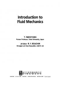
FIGURE 4a Modeling the progress of the Deacon reaction as a function of temperature using the Kochubei and Moin kinetic model and Reaction specific thermodynamics.
This work presents the kinetic analysis of measurements made in a isobaric, isothermal plug-flow reactor. From this data, a kinetic expression was developed: _ d[HCl] = k dt
1
* [Oz] * [HCl] *
[HCl]- [HCl]equil [HClJinitiat- [HCl]equil
(10)
where: [i] =concentration of specie i (moljliter), [i];nitiat =concentration of specie i at time= 0 (moljliter), and [i]equil =concentration of specie i at isobaric, isothermal condition (moljliter), and k 1 = 10 13 ·3 -+ 0 ·1 exp (
-
51500 ± 500caljmol) cm 3 R*T mohsec
(11)
From this data, calculations were made using an isothermal perfectly-stirred reactor (PSR) model (Glarborg et al., 1986). Residence time was arbitrarily fixed at 2 seconds. The resulting curves in Figure 4a does not extend past "' 1350 K, as this was the limit of the experimental work. The second curve in Figure 4a, labeled "Reaction specific thermodynamics", takes the same initial reactor scenario and models the reactor as an isobaric, isothermal equilibrium reactor. In this case, however, only four species are considered as possible reactants or products-Cl2 , HCl, 0 2 , and H 2 0. Calculation of final product mixtures is based upon the equilibrium constant described in Equation 9. Comparison of the two curves shows that at lower temperatures, the kinetic rate of the reaction is limiting and there appears to be very little formation ofC1 2 • The two curves begin to come together, as would be expected, as temperatures increase and at higher temperatures, HCl appears to be the dominant chlorine specie.
INCINERATION OF CHLORINATED HYDROCARBON WASTES
407
100
g
80
"p.. 0
~
"il ~
~
0/'
60
s
General
th~nnodynamics
o Utt>t·ature d{'.mt-nt,lry reactions (PSR)
§
·=u
! c
(;
40
~
~
20
0
500
1000
1500
2000
2500
3000
Temperature, K
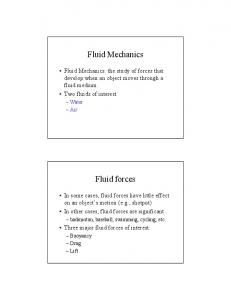
FIGURE 4b Modeling the progress of the Deacon reaction as a function of temperature using literature values for elementry kinetic reactions and general thermodynamics.
Figure 4b contains two similar curves with somewhat different results. The curve in Figure 4b labeled "General thermodynamics" is the result of equilibrium calculations using comprehensive thermodynamic models. In this case, the code used was CET89 (Chemical Equilibrium with Transport Properties, 1989), a product of the NASALewis Research Center (McBride, 1989). The code, rather than using equilibrium constants, describes the chemical equilibrium by minimizing the free energy of the system. Minimization of system free energy to determine chemical equilibria has some distinct advantages over the use of equilibrium constants, the most apparent is the reduction in "bookkeeping" in tracking reactions and specie development. In this way, it becomes easier to introduce any number of different chemical specie into the potential product mixture, provided thermodynamic data exists for the compound. The second curve, labeled "Literature elementary reaction (PSR)", presents the results of a series of calculations done using a PSR model (Glarborg et al., 1986). Once again, residence time was arbitrarily set at 2 seconds and the calculations were done for an isothermal, isobaric reactor. The kinetic data used for this model was a set of elementary reactions of the type used by the CHEMKIN series of subroutines and the values used were obtained from the literature. Reactions used in this form are represented in the general form:
(i=l,2, ... ,/)
(12)
where I = number of elementary reactions being considered, K = number of chemical species being considered, v =stoichiometric coefficients, and Xk =chemical symbol for
J.D. SMITH eta/.
408
the kth specie. Forward reaction rate constants are assumed to be of the following form: (13)
where A= pre-exponential factor (em-mol-sec-K), T= temperature (K), B =temperature exponent, and EA =activation energy (cal/mol). The reverse reaction rates are related to the forward reaction by the equilibrium constant for the reaction. The reaction set used for the PSR calculations can be found in Table II.
TABLE II Chemkin Reaction set for Kinetic Evaluation NO.
Reactions
I. 2. 3. 4. 5. 6. 7. 8. 9. 10. 11. 12. 13.
2.670 5.12E + 04 0+H 2 =0H+H 1.45E + 13 0.000 0+0H=0 1 +H 3.25E+ 13 0.000 0 + H0 1 = OH + 0 2 0+H 2 0 2 =OH + H0 2 1.33E + 11 0.000 0.000 0 + H1 0 2 = H 20 + 0 2 5.30E + 11 O+HCI=OH+CI 4.26E+ 10 2.870 0+CI 2 =CI+CIO 2.51E+12 0.000 0 + CIO = Cl + 0 2 5.70E + 13 0.000 0.000 0 + OCIO = 0 2 + CIO 3.30E + 11 0 + C\ 20 = CIO + CIO 1.75E + 13 0.000 0 +HOC!= OH + CIO 6.03E + 12 0.000 H+0 2 =0+0H 1.99E + 14 0.000 H + 0 2 + M = H0 2 + M 3.61E+ 17 0.720 Enhanced Third Body Efficiencies: H 2 0 = 18.6, H 2 = 2.9, N 2 = 1.3 9.76E+ 16 -0.600 H + H +Hz= Hz+ Hz -1.250 H +H + HzO= Hz+ H 2 0 6.00E + 19 H+OH+M=HzO+M 2.83E + 22 -2.000 Enhanced Third Body Efficiencies: H 2 0 = 5.0, N 2 = 0.78 4.28E + 13 H + HOz = Oz + H 2 0.000 H+H0 2 =OH+OH 1.69E + 14 0.000 H + H0 2 = 0 + H 2 0 3.01E+ 13 0.000 H + H 2 0= H 2 +OH 4.52E+08 1.600 H + H 2 0 2 = HOz + H 2 1.69E + 12 0.000 H +H 2 0 2 =H 2 0 +OH 1.02E + 13 0.000 H +HCI=Hz +CI 1.07E + 13 0.500 H +CI 2 =HCI+CI 8.59E+ 13 0.000 H + OCIO = CIO + OH 4.70E + 13 0.000 H +CI 20=CIO+HCI 2.47E + 13 0.000 H 2 +M=H+H+M 9.03E + 14 0.000 H 2 +Oz =OH +OH 1.70E + 13 0.000 H 2 + 0 2 = H0 2 + H 1.45E + 14 0.000 H 2 + Cl = HCI + H 1.45E + 13 0.000 H 2 +CIO= HCI+OH 3.00E +08 0.000 H 2 +CIO= HOC! +H 6.64E+03 0.000 OH + H 2 =H + H 2 0 1.02E + 07 1.600 OH + OH = 0 + H 2 0 1.51E + 09 1.140 0H+0H=H 2 0 2 9.03E+ 12 0.000 OH + H0 2 =H 2 0+0 2 2.89E+ 13 0.000 OH + H 2 0 2 = H0 2 + H 2 0 7.83E+ 12 0.000 OH+HCI=H,O+CI 3.27E + 11 1.650 OH +CI 2 = HOCI+CI 8.43E + 11 0.000
14. 15. 16. 17. 18. 19. 20. 21. 22. 23. 24. 25. 26. 27. 28. 29. 30. 31. 32. 33. 34. 35. 36. 37. 38. 39.
A
B
EA 6285.0 701.0 0.0 3974.0 3974.0 3509.0 2718.0 364.0 0.0 1252.0 4371.0 16802.0 0.0 0.0 0.0 0.0 1411.0 874.0 1721.0 18420.0 3755.0 3577.0 3100.0 1172.0 0.0 0.0 96071.0 48150.0 56635.0 4372.0 0.0 0.0 3298.0 99.0 0.0 -497.0 1331.0 -223.0 1788.0
INCINERATION OF CHLORINATED HYDROCARBON WASTES
409
TABLE II (Continued) NO.
Reactions
40. 41. 42. 43. 44. 45. 46. 47. 48. 49. 50. 51. 52. 53. 54. 55. 56. 57. 58. 59. 60. 61. 62. 63.
OH+CI=O+HCI OH+CI=CIO+H OH +CIO=H0 2 +CI OH + OCIO =HOC!+ 0 2 OH +HOC!= H 2 0 + CIO H0 2 = H +0 2 H0 2 + H0 2 = H 20 2 + 0 2 H0 2 +Ci= HCI+0 2 H0 2 +Cl=CIO+OH H0 2 + CIO =HOC!+ 0 2 H 2 0=H+OH H 2 0+Cl=0H+ HCI H 2 0 2 + M =OH +OH + M H 2 0 2 + Cl = HCI + H0 2 CI+Cl=CI 2 Cl+ HCI=Cl 2 +H CI+CIO=C1 2 +0 Cl + OCIO = CIO + CIO Cl + Cl 2 0 = Cl 2 + CIO Cl+ HOC!=Cl 2 +OH Cl 2 =Cl+Cl CIO+CIO=Ci 2 +0 2 CIO + CIO = OCIO + Cl HCI=H+CI
A
B
EA
5.90E + 12 1.51E + 14 6.62E + 12 2.71E + 11 1.81E + 12 1.21E + 19 1.87E + 12 LOSE+ 13 2.47E + 13 2.89E + 11 3.49E + 15 1.68E + 13 1.20E + 17 6.62E+ 12 2.51E+ 14 l.OOE+ 17 1.05E + 12 2.05E+ 13 3.61E + 13 1.81E + 12 2.32E + 13 4.94E+09 1.02E+09 4.40E + 13
0.000 0.000 0.000 0.000 0.000 - 1.180 0.000 0.000 0.000 0.000 0.000 0.000 0.000 0.000 0.000 0.000 0.000 0.000 0.000 0.000 0.000 0.000 0.000 0.000
5683.0 64061.0 -238.0 -1590.0 994.0 48414.0 1540.0 -338.0 894.0 -1391.0 105163.0 17229.0 45502.0 1947.0 -1800.0 47464.0 9121.0 -318.0 -252.0 258.0 46958.0 0.0 0.0 81753.0
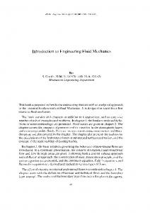
Differences between the kinetic and thermodynamic models in Figure 4b are similar to those found in Figure 4a. The reaction appears kinetically limited at lower temperatures and the two curves come together as the temperature increases. However, comparison between the two thermodynamic curves of Figures 4a and b highlights an interesting feature of this chemical system. Below "'1450 K, the calculated extent of reaction for HCl is essentially the same between the two models. Above this point, the more complex equilibrium model predicts a decrease in system HCl concentrations, whereas the more simple, equilibrium constant model predicted less HCl being affected by any reaction. The differences between the two models can be accounted for by monitoring other chlorine combustion species. As is shown in Figure 5, the simple equilibrium model does not take into account the formation and stability of Cl radical at moderate to high temperatures. Thus, any hydrogen that might combine with this Cl radical, as temperatures decreases, will have probably already combined with oxygen to form water. Hence, the remaining Cl radical will either form Cl 2 or chlorinate any organics in the post-combustion environment. The presence of this compound in the moderate to high temperature gases, resulting from the combustion of chlorinated hydrocarbons, may well account for differences between industrial furnace operation and equilibrium calculations done to model such devices (Bashkirova et al., 1989). Furthermore, this indicates that the mixing-limited ("fast chemistry") approximation is applicable at or above temperatures typical for combustion scenarios, provided the chemistry model takes into account the presence of species such as the chlorine radical. Realization of the gas-phase chemistry kinetic limitations will also determine under
J. D. SMITH eta/.
410 0.4 0.35 0.3 0.25
• Cl 0 HCI
: :
Mole fractions 0.2
r:.ac, :
0.15
0.1
o.os 0
t ~. ~I
::l
600 750 900 1050 1200 1350 1500 1650 1800 1950 2100 2250 2400 2550
Temperature, K
FIGURE 5 Distribution of chlorine species in the Deacon chemistry as a function of temperature.
what conditions realistic evaluations may be made in regards to final combustion product compositions.
RESULTS The first step in performing the TOX simulation was to develop the input files describing the system geometry (reactor dimensions) and operation data (inlet stream conditions, wall temperatures, etc.). The information used for this study represents a general TOX design adapted to generate steam (see Figure 6). The feed compositions and flow rates, shown in Table III, might represent typical process streams from various production plants. With the required input files, the simulations were performed.1 Phase 1: process evaluation
Given the inputs, a base case was established. Next, several separate simulations were performed for various combinations of the feed stream flow rates. Each case represented a combination of the nominal and/or maximum flow rate of fuel gas (taken as methane in these calculations), of combustion air, and of organic feed streams. The predicted HCl, Cl 2 , 0 2 , Cl, H outlet concentrations and average exit temperature for each case are shown in Table IV. 1 All CFD calculations presented in this work were performed on a SPARC 2 Sun Workstation. Typical calculation times ranged from two to five CPU minutes.
INCINERATION OF CHLORINATED HYDROCARBON WASTES
411
MODEL TOX GEOMETRY
6.1722
0.6096
0.0762
't
0.1778
Fuel Gas
--:t::==-
1.067
VentB (liquid) Vente (Gaseous)
i
Combustion Air
FIGURE 6 Geometric information describing the TOX examined during this study.
Although performing actual test burns for the cases identified in Table IV would be prohibitively expensive and time consuming, the incineration model was able to assess the impact that various operating conditions might have on expected emission levels. From these simulations, the estimated range of expected HCl and Cl 2 production was: Expected Cl 2 Concentration Range:
0.01-221 ppmv
Expected HCl Concentration Range:
3.9-6.4 mol%
Once the matrix of incineration simulations was performed, attention was given to the interesting cases identified during the study. Results listed in Table IV, indicate that Cases 4 and 5 represent the limiting cases. To better understand the causes for the predicted dramatic impact on Cl 2 production rates and on exit gas temperature, these cases were further investigated. One advantage of the CFD based incineration model is its ability to generate local profiles of velocity, temperature, and species (e.g., CH 4 , CO, HCl, and Cl 2 ). With these profiles, results from the limiting cases were closely examined to better understand the differences between each.
Case 5: excess 0 2 condition The first set of plots corresponding to Case 5 are shown in Figures 7-9. Important input data for this case includes: CASE5 Organic Feed (g/s): Combustion Air Feed (g/s): Fuel Gas Feed Rate (g/s):
390.0 1954.9 1.4
Inlet Temperature (K): Swirl Number§: Heat Loss(%):
§Swirl Number is a measure of tangential velocity in the secondary inlet stream.
298.15 0.3125 35%
J. D. SMITH et al.
412
TABLE III Vent feed rates to tox Nominal flows Component
Vent B (g/s)
Vente (g/s)
Vent A (g/s)
Combustion Air (g/s)
CH 4 4.06
Nz H 20 02 C4Hs C1 2 C0 2 HCI
0.66 3.59
CC\ 2 0 C 2 H 2 Cl 2 0 C4 H 80 C 4H 7 Cl0 C 4H 8 Cl 2 C4Hto0z C 8 H CI 2 0
17.64 35.28 105.84 8.82 8.82
0.19 0.76 0.09 0.09
Total Feeds (g/s):
176.40
9.45
16
Total Mass (g/s)
1.43
1.43 1213.11 0.00 385.77 3.59 7.29 7.62 23.75 17.03 8.27 2.95 17.64 35.47 106.60 8.91 8.91
1.43
1848.35
39.06
39.06 1529.60 0.0 493.67 7.19 12.90 13.50 42.10 30.20 14.60 3.90 22.70 45.79 137.71 11.59 11.59
39.06
2416.10
1209.05 15.15
369.96
7.29 7.62 23.75 17.o3 8.27 2.95
co
~
Fuel Gas (g/s)
82.06
1579.01
Maximum flows CH4
8.13
Nz H 20 02 C4Hs Cl 2 C0 2 HCI
1.32 7.19
1521.47 26.80
465.55
12.90 13.50 42.10 30.20 14.60 3.90
co
CC1 2 0 C 2 H 2 CI 2 0 C 4 H 80 C 4 H 7 CIO C 4 H 8 CI 2 c..HtoOz C 8 H 16Cl 2 0
22.70 45.50 136.20 ll.40
11.40
0.39 1.51 0.19 0.19
Total Feeds (g/s):
227.10
18.92
144.00
1987.02
Both the axial velocity and local gas temperature are shown first (Figure 7a and b). A maximum velocity of nearly 60m/s is predicted near the reactor entrance. This is likely caused by the temperature driven was expansion associated with combustion (Figure 7a). A weak recirculation zone is predicted near the reactor wall in the quarl section (lower left-hand section of plot). Toward the reactor exit, the gas flow is fully developed with an exit velocity of about 15 m/s.
413
INCINERATION OF CHLORINATED HYDROCARBON WASTES TABLE IV Predicted outlet gas composition and temperature
Case No. 1. 2. 3. 4. 5.¥ 6.§
Organic Feeds (kg/s)
Fuel Gas (kg/s)
Combustion Air (kg/s)
0.266 0.266 0.390 0.390 0.390 0.390
0.0014 0.0014 0.0014 0.0694 0.0014 0.0187
1.99 1.58 1.58 1.95£ 1.99 1.99
Exit Gas Composition HCl Cl 2 (mol%) (mol%) (ppmv)
Exit Gas Temperature (K)
02
7.71 4.74 1.22 0.00022 3.96 1.53
221 89 61 0.013 75 20
3.87 4.73 6.39 5.54 5.32 5.22
1446 1642 1813 1398 1695 1811
Note: Cases 1-3 indicate a trend in decreasing exit Cl 2 with decreasing excess air. This observation agrees with industrial operating experience. Also, as excess air is decreased exit temperature raises as you approach the stoichiometric limit. £ Represents Stoichimetric Combustion Air "Case selected as representing typical operating conditions for BIF pre certification work. §Case using 25% excess air feed to system
Axial velocity (m/sec)
::m
~
rm:
m
,P.·:
m
1m'
'
1500
1600 ~
rn:;J
m
_,...__
1550
rn:il
mil
mil
m
~~~
.....-...'-:"2.
-
l'r!'O'I
Gas temperature profile (K) FIGURE 7 Axi-symetric prediction of axial velocity (a) and gas temperature(b) for Case 5 (4% excess air). Left border is reactor entrance, top border is reactor centerline, and right border is reactor exit (see Figure 6). Color shading indicates magnitude of variable (darker colors represent lower values and lighter colors represent higher values). Two distinct combustion zones (flames) are illustrated (1f 1 ~ 1350, T, 2 ~ 1600K). See COLOR PLATE I.
The predicted local gas temperature is shown in Figure 7b. The quarl region, clearly shown in this plot, has a wall temperature of 1000 K (preset boundary condition). A high temperature envelope ( > 1000 K) is predicted near the reactor entrance, associated with the initial combustion zone. The indication that the methane is consumed in this region is shown in Figure 8a. A cooler region exists near the reactor wall in the quarl region. This may be caused by the recirculation ofthe cooler gases fed
J.D. SMITH et al.
414
Methane ooocenttation profile (ppmv)
0
1193
2386
"3579
4772
Cuban monoxide concentration profile (ppmv)
FIGURE 8 Axi-symetric prediction of Methane concentration (a) and Carbon Monoxide concentration (b) for Case 5 (4% excess air). Left border is reactor entrance, top border is reactor centerline, and right border is reactor exit (see Figure 6). These predictions depict the CO formation and oxidation zones common to most two-flame combustion processes. See COWR PLATE II.
HO concentration profile (ppmv)
Cl2 concentration profile (ppmv)
FIGURE 9 Axi-symetric prediction of HCI concentration (a) and Cl 2 concentration (b) for Case 5 (4% excess air). Left border is reactor entrance, top border is reactor centerline, and right border is reactor exit (see Figure 6). A predicted maximum Cl 2 concentration of nearly 3200 ppmv occurs in the cooler reactor regions while an exit Cl, concentration of about 100 ppmv is predicted. See COWR PLATE III.
INCINERATION OF CHLORINATED HYDROCARBON WASTES
415
with the secondary feed stream. Also, the abnormally low prediction for gas temperature may be a result of using the uniform reactor heat loss. Finally, a second high temperature region ( > 1600 K) is predicted near the reactor exit. This is caused by the combustion of remaining fuel (organic vents) and by the CO oxidation reaction that occurs in this portion of the reactor. CO formation and oxidation (C0 2 formation) are shown in Figure 8b. The spatial nature of these predictions is illustrated by the high CO levels near the reactor centerline ( > 4000 ppmv) that decreases toward the reactor walls to essentially zero. Finally, predicted values ofHCl and Cl 2 concentrations are shown in Figures 9a and b. Figure 9a clearly shows the localized nature of the HC1jC1 2 chemistry in the combustion zone. The maximum predicted HCl concentration (20.6 mol%) is located early in the reactor (high temperature region) compared to a predicted exit HCl concentration of 5.3 mol%. Also, the maximum Cl 2 level (3600 ppmv) occurs just beyond the reactor quarl wall (low temperature region), compared to an exit Cl 2 concentration of 75 ppmv. This indicates how dramatically the local conditions effect the HCljC1 2 levels. This indicates those process variables affecting local regions of the reactor may be used to optimize emissions' levels. Case 4: stoichimetric conditions As shown in Table IV, the predictions associated with Case 4 indicated a much lower Cl 2 emission and a lower exit temperature. Therefore, this case was carefully analyzed to understand the reasons for the apparent difference. A second set of plots corresponding to Case 4 is shown in Figures 10-12. Important input data for this case includes:
CASE4 Organic Feed Rate (g/s): Fuel Gas Feed, Combustion Air (g/s): Fuel Gas Feed Rate (g/s):
390.0 Inlet Temperature (K): 298.15 1987.0 Swirl Number: 0.3125 69.4 Heat Loss(%): 35%
Although the axial velocity profiles for Case 4 are similar to those of Case 5, there are some interesting differences. First, the velocity region near the reactor inlet is higher than before and the recirculation zone near the wall in the quarl region is larger than before (see Figure lOa). Both these differences are caused by dissimilar temperature profiles throughout the reactor (see Figure lOb). First, the early centerline gas temperature appears to be about the same ("' 950 K) as before. Instead of two distinct high temperature zones (near the entrance and near the exit), in this case a single flame zone extends from the centerline reactor entrance to just beyond the quarl section. The flame also expands to the reactor wall and has a maximum temperature of approximately 1450 K. The low temperature zone ("' 400 K) in the quarl section of the reactor and the weak recirculating flow zone ("' - 1 m/s) from Case 5 have also changed. The gas temperature has increased ( > 1200 K) as has the recirculating velocity ("' - 5 m/s). The expansion of the high-velocity region near the reactor entrance, the stronger recirculation zone in the quarl region, and the increased gas temperature in the quarl region seem correlated to the relative amounts of natural gas organic feeds considered in the respective cases. Two factors can help explain the different results from these cases.
J. D. SMITH eta/.
416
Gas temperature profile (K)
FIGURE 10 Axi-symetric prediction of axial velocity (a) and gas temperature (b) for Case 4 (0% excess air). Left border is reactor entrance, top border is reactor centerline, and right border is reactor exit (see Figure 6). Color shading indicates magnitude of variable. (darker colors represent lower values and lighter colors represent higher values). One main combustion zone is predicted (T,- ~ 1450 K and T.,.. - 1350 K). See COLOR PLATE IV. Methane concentration profile (ppmv)
-1
0
1193
2386
4772
3579
Carbon monoxide concentration profile (ppmv)
----
- --
--
..
-
..
~~.
0
3230
!
..
~.
.-
.
• •
": ·', • •
.
... l
.
6460
9690
12920
FIGURE 11 Axi-symetric prediction of Methane concentration (a) and Carbon Monoxide concentration (b) for Case 4(0% excess air). Left border is reactor entrance, top border is reactor centerline, and right border is reactor exit (see Figure 6). Here the post-flame CO oxidation zone, shown in Figure 8, is not present. This results in a single flame with an predicted exit CO concentration of nearly 9000 ppmv. See COLOR
PLATE V.
INCINERATION OF CHLORINATED HYDROCARBON WASTES
417
HCI concelllration profile (ppmv)
~~~~~~:~~'~ . -o
/./
70000
50000
.
Cl2 concentration profile (ppmv)
FIGURE 12 Axi-symetric prediction of HCl concentration (a) and Cl 2 concentration (b) for Case 4 (0% excess air). Left border is reactor entrance, top border is reactor centerline, and right border is reactor exit (see Figure 6). Dramatically less Cl 2 formation is predicted (local maximum of 7 ppmv and exit concentrations less than 1 ppmv) in this case due to excess H + radical present from the increased fuel gas. See COLOR PLATE VI.
First, while Case 4 represents a near stoichiometric reactant mixture, Case 5 represents a reactant mixture having excess air. Examining Figure 8b, the CO oxidation that occurs midway down the reactor in Case 5 (due to the excess oxygen and turbulent mixing) is not observed in Case 4 (see Figure llb). Thus, higher exit CO levels ( > 8000 ppmv) are predicted which results in less energy release from the exothermic oxidation reaction of CO (AH, = - 282 KJ/mol) which leads to a lower exit gas temperature (1398 K). Another possible cause for the different temperature profiles might be related to how and where the organic vents are burned. In Case 5, the organic vents appear to be burned after the methane is consumed. This would lead to two reaction zones: one where fuel gas is burned (early flame zone), and one where organic vents ignite resulting in a secondary flame. These two high temperature regions, observed in Figure 7b, would lead to a higher exit temperature. In either case, the relative amounts offuel gas and oxidizer are critical to the predicted combustion characteristics inside the reactor. What is more important, they dramatically affect the HCljC1 2 chemistry in the reactor as seen in Figures 12a and b. In both cases, the predicted exit HCl concentration is greater than 5 mol% (see Table IV). However, the predicted exit Cl 2 concentration in Figure 12b is nearly two orders of magnitude less than that for Case 5. The same general trends show up in both cases: maximum Cl 2 concentrations near the outer wall just past the quarl section that is reduced to uniform exit concentrations toward the reactor exit. Two factors explain the significant differences in the H CljC1 2 concentrations for the different cases: 1) H Cl is favored over Cl 2 at higher temperatures, and 2) lower 0 2 concentrations favor Cl 2 • For
418
J. D. SMITH et al.
Case 5, the early maximum of Cl 2 may also be due to poor mixing of 0 2 with the fuel and the accompanying low gas temperatures (see Figure 9b). Similarly, for Case 4, the global maximum is in the same region, but, now the effect of higher gas temperature (favors HCl formation) results in significantly less Cl 2 formation. Thus, both the temperature effect and the oxygen effect are important. This prediction is most interesting when considering the slight increase in HCl production accompanied by the dramatic decrease in Cl 2 production. In an attempt to validate this predicted behavior, the two conditions were reproduced in the field by adjusting the fuel gas, and the organic feed rates accordingly. The flame inside the TOX was visually monitored along with the exit gas temperature during the two tests. For the high waste feed rate/low fuel-gas feed rate scenario, the flame appeared to nearly fill the entire combustion zone of the TOX. As the fuel gas was increased while holding the organic feed rate constant, the visible flame front appeared to retreat toward the front of the burner. Also, the exit temperature decreased by nearly 200 K during this test. Although this is only a limited amount of data, it provided some degree of validation of the predictions. Phase 2: trend analysis of process variables
Having identified and performed the base case calculation, established and performed calculations for nominal and maximum flow conditions, and investigated some limiting cases, the incineration model was next used to perform a trend analysis of various operating variables that are important in TOX operation. Variables examined during this analysis included reactor heatloss (indirectly effects exit temperature) and inlet combustion-air swirl-level. The results of this study are shown in Figures 13-15. Reactor heat loss may be correlated to the amount of insulation on the furnace shell and can be monitored by outer-shell surface temperature. Increased heat loss corresponds to a higher shell temperature and results in more energy lost from the system. This leads to a decreased exit temperature as predicted by the model (see Figure 13b). Predicted exit temperatures range from nearly 1830 K (no heat loss) to about 980 K (50% heat loss). As expected, the relationships between heat loss and exit temperature is essentially linear. As described earlier, the HCljC1 2 chemistry is determined by the local temperature and gas composition. As reactor heat loss is varied, the local temperature profile is also varied which affects the local chemistry. Figure 13a shows the relationship between HCl, Cl 2 , and Cl radical concentration. This relationship is very nonlinear since it is also a function of the local composition that is affected by the turbulent mixing process. High temperature is known to favor HCl formation while Cl 2 is favored at lower temperatures. This predicted trend agrees well with what might be expected considering the relative strengths of the H-Cl bond and the Cl-Cl bond. In this study, the importance of Cl and H radicals can be seen. At high temperatures (low heat loss), a mass flow of less than 155 g/s HCl is predicted while less than 0.5 g/s Cl 2 mass flow is predicted. The relative amounts ofC1 2 and Cl radical (15 gjs) illustrate the importance of the Cl radical on local flame chemistry. Also, the decreases in the Cl radical concentration and the increase in HCl concentration for lower temperatures indicates how Cl affects HCl formation. At these temperatures, essentially all the Cl radical
INCINERATION OF CHLORINATED HYDROCARBON WASTES
419
Effect of Exit Temperature on CL2/HCL Split
165
12
9
1
160
6
CL2
l :
155
~.~
~
f l
~
0 1==::!b~~===r=:l:__;:__l15o 0
0.1
0.2
0.3
0.4
0.5
b)
g
2000
i
1800
~
~ 1600
J ~
1400
0
0.1
0.2
0.3
0.4
0.5
Heat Loss
FIGURE 13 Effect of Heat loss on Gas Temperature and HCI/Cl 2 exit mass flowrates: a) increasing reactor heat lose causes a decrease in exit temperature, b) low exit temperatures result in changing exit HClfCI 2 mass flows (concentrations).
combines with the H radical to form HCI. However, only when the temperatures decrease to the point where Cl 2 may exist, and when the H radical is depleted, does the Cl 2 concentration begins to increase. Turbulent mixing, also critical to the combustion process, was studied by varying the swirl level (amount of tangential velocity) in the combustion air feed stream. Physically, this represents the case where the swirl vanes are modified in the burner assembly. As can be seen in Figures 14a and b, increasing swirl has a significant effect on the amount ofHCl formed, while it has only a small effect on the Cl 2 formation. This is though to be due to the stability of HCl molecule compared to that of Cl 2 (Chuang and Bozzelli, 1986; Ho et al., 1992). Since the local chemistry, the local gas temperature field, and the local turbulent mixing are all related, the effect of swirl on the gas temperature was also studied. As seen in Figure 15, varying the swirl level had a minimal effect on the exit temperature.
420
J.D. SMITH et al.
Effect of Swirl on HCI Formation 220
220 210
§ £"
I0
:>:
a)
[HCl] = 16653- 4.93*SN + 39.67*SN•2 R =0.9932
210
200 / /
190 /
180 170
_._
~·--
160
0
/
--··
190
/
180 170 160
0.8
0.4 0.6 Swirl Number
0.2
•
200
"'
Effect of Swirl on CIZ,CI formation 5
s
b)
[Cl2] = 1.13 + 4.45*SN - 3.26*SN•2 A= 0.8961
4
4
[CI] = 2.17 - 2.25*SN + 0.92*SN•2 A= 0.9750
~
.
...... ,..._::-. -. .... ··--- ......
~
j
0
• ---
!-
#
2
/
ci u
0 0
..... -·
3 2
_____
-.-
Cl2
C!
0 0.4
0.2
0.8
0.6
Swirl Number
FIGURE 14 Predicted effect of Swirl (Turbulence level) on HCI/Cl 2 concentrations: a) Increasing swirl causes an increase in exit HCl composition, b) Increasing swirl results in an increase in Cl 1 (better mixing causes reduces the Cl radical).
Effect of Swirl on Exit Temperature 1600
1600 ET = 1563.5 - l79.3*SN + 24.5*SN"2 R =0.9711
@
J ~
fl ' f
1550
1550
'
1500
'' 't f''
1500
'
1450
....
1450
f'' . . '
1400
0
0.2
0.4 0.6 Swirl Number
1400
0.8
FIGURE 15 Predicted effect of swirl level (tangential velocity component) of combustion air on exit gas temperature. Increased mixing causes lower exit temperatures due to changing flame position in the reactor.
INCINERATION OF CHLORINATED HYDROCARBON WASTES
421
Increasing the swirl number from 0.0 to 1.0 (representing an increase in tangential momentum of the feed stream) caused the exit temperature to decrease nearly 10% ("' 150 K). This is due to the fact that the exit gas stream is well mixed and increased mixing upstream has little impact on the final state of the stream. Therefore, this effect appears to be negligible.
CONCLUSIONS Based on the results of this study for this system, the following conclusions are made: 1. A CFD based incineration model has been used to predict general trends observed in TOX operation. The model has also been used to estimate expected HCijC1 2 ranges for various operating scenarios. 2. An increase in fuel-gas feed rate can lead to a significant reduction in Cl 2 formation and a lower exit temperature. This is caused by changing the local combustion conditions which directly affect the HC1/Cl 2 chemistry. 3. Exit gas temperature is directly related to reactor heat loss. An 50% increase in heat loss results in a 850 K decrease in exit temperature. This is important when considering the available heat for steam generation in a boiler. It also affects the erosion and wear on the back wall refractory of a typical TOX unit. 4. Reactor heat loss indirectly affects the HC1/Cl 2 exit levels. Changes to the temperature profile have a direct effect on the local chemistry and mixing which determine the amount of HC1/Cl 2 formed through out the reactor. 5. Swirl level of the combustion air feed stream has an impact on the HC1/Cl 2 production (increased mixing near the reactor entrance). It has a less significant impact on the exit temperature since the gases are well mixed at the reactor exit. 6. The ratio of organic vent feed rate to fuel gas feed rate appears to have the greatest impact on the exit gas temperature and the HCijC1 2 production. Increasing the fuel gas feed rate while maintaining the organic vent feed rate constant appears to lower the exit temperature by changing the flame position and CO oxidation. The local mixing and gas temperature result in significantly different local and exit HCijC1 2 concentrations. Considering the predicted trends, optimum operation of this TOX would be achieved by maintaining a fuel gas to organic vent feed rate ratio of about 0.18 and a minimum of 7-10% excess oxygen in the effluent gases. These observations, may provide improvements in the combustion efficiency and may help reduce operating costs. This work demonstrates the impact of CFD based incineration modeling on TOX design and operation. Prior to applying the recommendations, plant validation should be done to confirm the predictions for specific units. Together with experimental testing, modeling results can help identify the possible operating envelope for specific TOXs. Used together, experimental testing and process simulation may help optimize plant operation and increase profitability that may ultimately enhance the competitive advantage of thermal oxidization as a means for hazardous waste treatment.
422
J.D. SMITH et al.
REFERENCES Altwicker, E. R., Kumar, R., Konduri, N. V. and Milligan, M.S. (1990). 'The Role of Precursors in Formation of Polychloro-Dibenzo-p-Dioxins and Polychloro-Dibenzofurans During Heterogeneous Combustion," Chemosphere, 20, Nos. 10~ 12, 1935. Arnold, C. W. and Kobe, K. A. (1952). "Thermodynamics of the Deacon Process," Chern. Eng. Prog., 48,293. Bashkirova, S. G., Savchuk, A. M., Solov'eva, T. A. and Libman, B. Ya. (1989). "Source of the Formation of Chlorine in the Incineration of Liquid Organochlorine Waste Products," translated from Khimi, Promyshl., 21 (3), 178. Buice, J. (1991) Private Communication. The Dow Chemical Company, Freeport, TX. Chang, D.P. Y., Nelson, W. S., Law, C. K., Steeper, R. R., Richards, M. K. and Huffman, G. L. (1989). "Relationships Between Laboratory and Pilot-ScaleCombustion of Some Chlorinated Hydrocarbons," Env. Prgs., 8 (3), 152. Chaudhry, G. G., Olie, K. and Hutzinger, 0. (1982). "Mechanisms in the Thermal Formation ofChlroinated Compounds Including Polychorinated Dibenzo-p-Dioxins", pp. 275~301, in Chlorinated Dioxins and Related Compounds: Impact on the Environment, Ed. by Hutzinger, 0., Frei, R. W., Merian, E. and Pocchiari, F., Pergamon Press, Oxford. EPA, (1991). "Part III: Burning of Hazardous Waste in Boilers and Industrial Furnaces; Final Rule," Federal Register: Rules and Regulations 56, 35. Fletcher, T. H. (1983). "A Two-Dimensional Model for Coal Gasification and Combustion," Ph.D. dissertation, Department of Chemical Engineering, Brigham Young University, Provo, UT. Glarborg, P., Kee, R. 1., Grear, J. F., Miller, J. A. (1986). "PSR: A FORTRAN Program for Modelling Well Stirred Reactors," Sandia National Laboratories Report SAND 86-8209. Gupta, A. K. ( 1984). "Combustion of Chlorinated Hydrocarbons," Chern. Eng. Commun. 41, 1. Graham, J. L., Hall, D. L. and Dellinger, B. (1986). "Laboratory Investigation of Thermal Degradation of a Mixture of Hazardous Organic Compounds," Environ. Sci. Techno/., 20, 703. Hixson, E. M., YanDell, R. D., Smith, J.D. (1993). "Predicting Chlorine Formation in an ortho-DichlorobenzenejAir Laminar Diffusion Flame" presented at Advanced Combustion Engineering Research Center's Seventh Annual Conference, Park City, UT, March 2~5. Ho, W. P., Barat, R. B. and Bozzelli, J. W. (1992). "Thermal Reactions of CH 2 Cl 2 in H 2 /0 2 Mixtures: Implications for Chlorine Inhibition of CO Conversion to C0 2 ," Combust. Flame, 88:265. Kiang, Y., Metry, A. A. (1982). Hazardous Waste Processing .Technology. "Thermal Processing Technologies." pp. 190~201, Ann. Arbor Science Publishers Inc./ The Butterworth Group. Kochubei, V. F., Moin, F. B. (1976). "Thermodynamics and Kinetics of Thermal Oxidation of Hydrogen Chloride by Oxygen," translated from Zhurnal Prikladnoi Khimii, 49 (10), 2220~2223. McBride, B. J. (1989). "CET89-Chemical Equilibrium with Transport Properties, 1989," NASA SP-273, NASA-Lewis Research Center. Peters, N. (1991). "Length Scales in Laminar and Turbulent Flames," Prog. Astro. Aero., 35, 155~ 183. Rasband, M. W. (1988). "PCGC2 and the Data Book: A Concurrent Analysis of Data Reliability and Code Performance," M. S. Thesis, Dept. of Chern. Eng., Brigham Young University, Provo, UT. Senkan, S. M. ( 1982). Detoxication of Hazardous Waste, Ann Arbor Science, 61 ~92. Senkan, S. M. (1988). "Thermal Destruction of Hazardous Wastes: The Need for Fundamental Chemical Kinetic Research," Environ. Sci. Techno/., 22, 368. Shaub, W. M., Tsang, W. (1983). "Dioxin Formation in Incinerators," Environ. Sci. Techno/., 17,721. Smith, P. 1., Fletcher, T. H. and Smoot L. D. (1981). "Model for Pulverized Coal Fired Reactors," 18th Symposium (International) on Combustion, The Combustion Institute, Pittsburgh, PA, 1285. Smoot, L. D., Christensen, K. R. (1985). "Data Book: For the Evaluation of Pulverized-Coal Reaction Models." Final Rept. (Vol. 3), Prepared for U.S. D.O.E., Cont. No. DE-AC21-8l MC16518, January. Smoot, L. D. and Smith, P. 1. (1985). Coal Combustion and Gasification, Plenum Press, New York, NY. Taylor, P. H. and Dellinger, B. (1988). "Thermal degradation Characteristics of Chloromethane Mixtures," Environ. Sci. Techno/., 22, 438. Takagi, T., Shin, H. and Ishio, A. (1981 ). "Properties of Turbulence in Turbulent Diffusion Flames," Combust. Flame, 40, 121. Van Dell, R. D. and Mahle, N.H. (1990). "The Role of Carbon Particle Surface Area on the Products of Incomplete Combustion (PICs) Emissions," Chapter 7, Emissions From Combustion Processes: Origin, Measurement, Control. R. E. Clement and R. 0. Kagel, Eds., pp 93~ 177, Lewis Publishers, Chelsea, Michigan. Van Dell, R. D. and Mahle, N.H. (1992). "A Study of the Products of Incomplete Combustion· and Precursors Produced in the Flame and their Post Flame Modification from the Combustion of a-Dichlorobenzene in a High Resolution Laboratory Thermal Oxidizer," Comb. Sci. Tech., 85, 327.
INCINERATION OF CHLORINATED HYDROCARBON WASTES
423
Van Dell, R. D. and Shadoff, L.A. (1984). "Relative Rates and Partial Combustion Products from the Burning of Chlorobenzenes and Chlorobenzene Mixtures," Chemosphere, 13, 177. Wall, C. K. (1984), "Heat and Mass Transfer in Combustion: Fundamental Concepts and Analytical Techniques," Prog. Energy Combust. Sci., 10,295-318. Wendt, J. 0. L. (1980). "Fuddamental Coal Combustion Mechanisms and Pollutant Formation in Furnaces," Progr. Energy Combust. Sci. 6, 201. Young, C. M. and Voorhees, K. J. (1992). "Thermal Decomposition of 1, 2-Dichlorobenzene Part II: Effect of Feed Mixtures," Chemosphere, 24, (6), 681.