T. Aroui Y. Koubaa
Regular paper
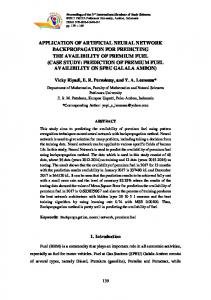
A. Toumi Application of Feedforward Neural Network for Induction Machine Rotor Faults Diagnostics using Stator Current Faults and failures of induction machines can lead to excessive downtimes and generate large losses in terms of maintenance and lost revenues. This motivates motor monitoring, incipient fault detection and diagnosis. Non-invasive, inexpensive, and reliable fault detection techniques are often preferred by many engineers. In this paper, a feedforward neural network based fault detection system is developed for performing induction motors rotor faults detection and severity evaluation using stator current. From the motor current spectrum analysis and the broken rotor bar specific frequency components knowledge, the rotor fault signature is extracted and monitored by neural network for fault detection and classification. The proposed methodology has been experimentally tested on a 5.5Kw/3000rpm induction motor. The obtained results provide a satisfactory level of accuracy. Keywords Feedforward neural network, Diagnosis, induction motors, rotor faults, single
phase stator current 1. INTRODUCTION Induction motors play a pivotal role in industry and there is a strong demand for their reliable and safe operation, and the motor can be exposed to different hostile environments, misoperations, and manufacturing defects. Internal motor faults ( e.g., short circuit of motor leads, interturn short circuits, ground faults, bearing and gearbox failures, broken rotor bar and cracked rotor end-rings), as well as external motor faults (e.g., phase failure, asymmetry of main supply and mechanical overload), are expected to happen sooner or later[1]. Furthermore, the wide variety of environments and conditions that the motors are exposed to can age the motor and make it subject to incipient faults. These incipient faults, or gradual deterioration, can lead to motor failure if left undetected. The major faults of electrical machines can broadly be classified according to the main components of a machine: stator related faults, rotor related faults, bearing related faults and other faults [2]. Early fault detection allows preventative maintenance to be scheduled for machines during scheduled downtime and prevents an extended period of downtime caused by extensive motor failure, improving the overall availability of the motor driven system. With proper system monitoring and fault detection schemes, the costs of maintaining the motors can be greatly reduced, while the availability of these machines can be significantly improved. Many engineers and researchers have focused their attention on incipient fault detection and preventive maintenance in recent years. There are invasive and noninvasive methods for machine fault detection, they can be described as [3,4]:
Research Unity of Industrial Process Control (UCPI), National Engineering School of Sfax (ENIS), B.P.: W 3038 Sfax-Tunisia
[email protected],
[email protected],
[email protected] Copyright © JES 2007 on-line : http://journal.esrgroups.org/jes/
Electromagnetic field monitoring, search coils, coils wound around motor shafts (axial flux related detection), Temperature measurements, Infrared recognition, Radio frequency (RF) emissions monitoring, Noise and vibration monitoring, Chemical analysis, Acoustic noise measurements, Motor current signature analysis (MCSA).
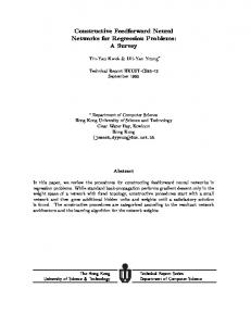
Fig.1. Types of induction machine faults The noninvasive methods are more preferable than the invasive methods because they are based on easily accessible and inexpensive measurements to diagnose the machine conditions without disintegrating the machine structure [7]. Recently, artificial intelligence (AI) techniques have been proposed for the noninvasive machine fault detection [6, 7]. They have several advantages over the traditional modelbased techniques [3, 4]. They require no detailed analysis of the different kinds of faults or modeling of the system. These AI-based techniques include expert systems, neural network and fuzzy logic. This paper deals with diagnosis problems of the induction motors in the case of rotor faults. A supervised neural network is used for fault and fault severity classification. The supervised neural network proposed is a multi-layer feedforward neural network. Neural networks are trained and tested using measurement data of stator current spectra. Tests were performed at different operating load conditions. The obtained results indicate that the proposed neural network approach is promising for not only detecting machine faults, but also estimating the severity of the faults via monitoring a single-phase stator current signal. 2. IMPLEMENTING ARTIFICIAL NEURAL NETWORKS Fig.2 describes the main steps of a diagnostic procedure, based on the single-phase stator current signal: ¾ First, the signal pre-processing converts the time domain stator current signal into a usable frequency domain spectrum. Then a signature extraction determines which frequencies should be monitored by the neural network,
¾ Finally, the neural network is used to automatically diagnose and discern between Healthy and faulty induction motor. 2.1. Signal pre-processing The motor stator phase line current is the signal used as a basis for the condition monitoring of the rotor faults. The preprocessor converts the sampled signal to the frequency domain using an FFT algorithm. The spectrum generated by this transformation includes only the magnitude information about each frequency component. Signal noise present in the calculated spectrum is reduced by a predetermined number of generated spectra. This can be accomplished by using spectra calculated from multiple sample sets.
Stator current
Time (s)
Frequency
Extraction of frequency signatures
Artificial Neural Networks
Rotor Conditions
Normal
Faulty
Fig. 2. Structure of the Artificial Neural Network rotor fault diagnosis system
2.1.1.Sampled signal The sampled input signal from a hall effect sensor is collected at an equal sampling time which can be expressed as x(n), where n=0,1,2,…,N-1 and N is the number of samples. 2.1.2.windowing function A window is a time-domain weighting function applied to the input signal. A window is a filter used to remove signals that are not periodic within the input time record. This makes the input time record appear to be a periodic signal, usually by forcing the amplitude to zero at both ends of the time record. Selecting the proper data window (such as Hanning, Hamming, Kaiser, Blackmann or Bartlett. We can see the difference between these N-point windows functions in Fig.3) can prevent leakage of energy across the frequency spectrum caused by transforming signals that are not periodic within the time record. The windowing function multiply the sampled signal by a proper data window w(n). The windowing data is expressed as wx(n) = w(n).x(n)
(1)
1 Hanning Hamming Blackmann Bartlett Kaiser
Windowing function
0.8
0.6
0.4
0.2
0 0
N-1
Sampled Signal Number
Fig. 3. Windowing functions
2.1.3.Fast Fourier Transform(FFT) Within each sample sets, applying FFT (Fast Fourier Transform) can convert time domain signals wx(n) into the frequency domain[8,9].
1 WX ( f ) = N
N −1
∑ wx(n) e
− j 2π n
f N
,f=0,1,2,…,N-1.
n = 0
where f is the discrete frequency. The Power spectral density (PSD) can be estimated by the following expression [8,9]:
(2)
PSD( f ) =WX ( f )WX ( f )
(3)
where WX ( f ) denotes the complex conjugate. 2.1.4. Ensemble averaging The ability to average a series of measurements is useful to discriminate between noise and components that are actually part of the signal. This ensemble-averaging technique is very effective for determining the frequency content of a signal buried in a random noise. The PSD from predetermined number (K) of generated spectra can then be averaged to give the following estimates
PSD ( f ) =
1 K
K −1
i
∑
= 0
PSDi ( f )
(4)
2.2. Extraction of signatures: The problem concerning the extraction of the signature is now considered. The extraction is the process used to pick up signals of importance and reduce the large amount of spectral information. The rotor faults in induction motors can be detected by monitoring any abnormality of the motor current spectrum amplitudes at several certain frequency components. These frequency components are located around the main frequency line and are determined according the number of poles and mechanical speed of the motor. However, there are other effects that may obscure the detection of the broken rotor bar fault or cause false alarms. For example, torque oscillation that can produce stator currents with the frequency values the same as the monitored frequencies [10]. 2.2.1. Motor current spectral components for broken rotor bar Kliman [11], Thomson [12], Filippetti [1] and nandy [2] have used the motor current signature analysis (MCSA) methods to detect broken bar faults by investigating the sideband components, fb, around the supplied current fundamental frequency:
fb = (1 ± 2s ) f s
(5)
where s is the slip and fs is the supply frequency. While the lower sideband is specifically due to broken bar, the upper sideband is due to consequent speed oscillation. In fact, some works [1,9] show that broken bars actually give rise to a sequence of such sidebands given by:
fbc = (1 ± 2ks ) f s ,k = 1, 2, 3, ……
(6)
Fig.4 and Fig.5 reports the experimental stator currents spectrum affected by the sideband components at frequencies (1±2s)fs and (1±4s)fs respectively in case of one and two broken bars.
From Fig.4 and Fig.5, it is important to note that, as the fault progresses, its characteristic spectral components continue to increase over time. Therefore, the correlation between the amplitude of these components and the fault extent is the issue of the diagnostic system. 0
-20
PSD (dB)
-40
-60
-80
-100
-120
-140 25
30
35
40
45
50
55
60
65
70
75
frequency (Hz)
Fig.4. Experimental plot of the stator current spectrum around fundamental with one broken bar 0
-20
PSD (dB)
-40
-60
-80
-100
-120 25
30
35
40
45
50
55
60
65
70
75
frequency (Hz)
Fig.5. Experimental plot of the stator current spectrum around fundamental with two broken bars 0
-20
-40
PSD (dB)
-60
-80
-100
-120
-140
-160
-180 220
225
230
235
240
245
250
255
260
frequency (Hz)
Fig.6. Experimental plot of the stator current spectrum around 5th harmonic with two broken bars
There are other spectral components that can be observed in the stator line current due to broken rotor bar fault. The equation describing these frequency components is given by Didier [9]:
⎡⎛ k ⎞ ⎤ f hbc = ⎢⎜ ⎟ (1 − s ) ± (1 + 2η ) s ⎥ f s ⎣⎝ p ⎠ ⎦ where fhbc is the detectable broken bar frequencies;
(7)
k =3,5,7,9,11,13,…….. and η=0,1,2,3,. p
Monitoring the amplitude of these components can be used to discriminate between rotor anomalies and oscillating load torque. Fig.6 shows the experimental plot of the stator currents spectrum affected by these components around 5th harmonic with two broken bars. 2.3. Artificial Neural Networks (ANN) Artificial neural networks (ANN) are used to recognize and classify complex fault patterns without much knowledge about the system they deal with. They are designed to mimic the human nervous system using massively parallel nets composed of many computational elements connected by links with variable weights. Of all the ANNs, the multi-layer feedforward artificial neural network, trained using the back-propagation algorithm, is the most commonly and flexibly used [3]. Its typical architecture, which contains the input layer, a number of hidden layers and the output layer, is shown in Fig.7. Input layer
l=1
Hidden layers
l=2
Output layer
l=L
Fig.7. A multi-layer feedforward artificial neural network architecture Initially, an input pattern is applied to the input layer. Then signals propagate forward, level by level, through the hidden layers and the output layer produces the network output. Each neuron in a layer (except the ones in the input layer) sums up their input value with interconnection to its associated weight and corresponding bias to form its own scalar output. The bias is added to shift the sum relative to the origin, and this quantity passes through a non-linear activation function, providing an output value.
We define the input vector to the network X=[x1,x2,…,xn]T and output vector Y=[y1,y2,…,ym]T where n is the number of input layer and m is the number of output layer neurons. Each layer is represented by l, i.e., input layer (l=0), hidden layers (l=1,2,3…L-1), and output layer (l=L) and each neuron in the hidden and output layer receives signals v=[v1,v2,…,vk]T from the neurons of the previous layer, scaled by the weights wj=[wj1,wj2,…,wjk]T. The activity level of the jth neuron in layer l is obtained as [8]:
⎡ k ⎤ o j = f j ( Net j ) = f j ⎢ ∑ ( w jiν i ) + b j ⎥ ⎣ i =1 ⎦
(8)
where oj is the activity level (output) of the jth neuron, Netj is the input of the jth neuron, fj is the activation function of the jth neuron, wji is the connection weight from the ith neuron to the jth neuron, vj is the activity level of the ith neuron in the prior layer and bj is the bias term of the jth neuron. The active function defines the output of a neuron in terms of the activity level at its level. There are three basic types of activation functions: threshold, piece-linear and sigmoid[3]. The sigmoid function is by far the most common activation function. In this paper the tan-sigmoid transfer function is used, which generates outputs between -1 and +1. Its definition is expressed in equation (9):
f ( Net j ) =
1 1 − −2 Net j 2 Net 1+ e 1+ e j
(9)
The backpropagation algorithm is used to train the network [3]. The connection weights are iteratively adjusted so that the error between the network output and the desired output (target) for a given reference input is minimized. The error goal is expressed as the sum of the squared error (SSE), calculated as follows: m
SSE = k
∑ (t = 1
k
− yk )
2
(10)
where tk represents the desired output of the kth neuron in the output layer. Learning continues iteratively until the sum of the squared error is below a certain goal. The incremental change of weight from the ith neuron to the jth is computed by[3,14]:
Δw ji (t + 1) = ηδ j oi + αΔw ji (t )
δ k = (tk − ok ) f k' ( Netk
)
⎛
(12)
⎞
δ q = f q' ( Netq ) ⎜ ∑ δ k wkq ⎟ ⎝
k
(11)
⎠
(13)
where Δwji(t) is the incremental change in the weight wij at time t, tk is the desired output of the kth neuron in the output layer, η is the learning rate and α is the momentum. The momentum term ( α Δw ji (t ) ), included in the weight update equation to try to avoid a local minimum [3]. Equation (12) holds for the kth neuron in the output layer and (13) holds for the qth neuron in the hidden layer. 2.4. Data normalization In order to improve the neural network performance, the data must be well-processed and properly-scaled before inputting them to ANN. The normalization process was required to restrict the range of the patterns for input into the neural networks. In this study, the inputs to the neural network are normalized between [-1,+1] by equation(14):
⎛ x − xmin ⎞ xn = ⎜ ⎟ ×1,8 − 0,9 ⎝ x − xmax ⎠ where xmax
(14)
is the maximum magnitude of the input vector and xmin
is the minimum
magnitude of the input vector 3. EXPERIMENT SETUP AND MOTOR DATA SPECIFICATIONS The characteristics of the 3 phase induction motor used in our experiment are listed in Table1. 3-phase 380V
Motor
Load
Current sensor
Data Acquisition & treatment Data Acquisition
Data Treatment
Current spectrum 0
20
15
-20
10
-40 5
-60 0
-5
-80
-10
-100
-15
-120 30 -20
1
1.01
1.02
1.03
1.04
1.05
1.06
1.07
1.08
1.09
35
40
45
50
55
60
65
70
1.1
Artificial Neural Network Fault detection/Fault severity evaluation
Fig.8. Block diagram of the experimental neural network based detection system
Table 1. Induction motor Characteristics used in the experiment Description Power Input Voltage Full load current Supply frequency Number of poles Number of rotor slots Number of stator slots Full load speed
Value 5.5 kW 220/380 V 20.6/11.9A 50 Hz 2 28 36 2875 rpm
Fig. 9. View of the experimental setup The needed load of the induction motor was established by connecting the test motor to an eddy current brake via a flexible coupling, as seen in Fig.9. In order to allow tests to be performed at different load levels, the brake DC supply current is controllable. A current Hall Effect sensor was placed in one of the line current cables. The stator current was sampled with a 4 KHz sampling rate and interfaced to a Pentium PC by an ARCOM acquisition board. The overall data collection scheme is depicted in Fig.8. The motor was tested with the healthy rotor and with two faulty rotors that had respectively one and two broken rotor bar. The bars were broken by drilling holes through them. 3.1. Machine slip computation The current spectrum components depend on the machine speed or slip. Therefore to avoid the need to measure the machine speed using conventional transducers (observing consequently, the non invasive criteria). To solve this problem, we choose to calculate the rotor slot harmonics given by the following equation:
⎡⎛ N ⎞ ⎤ f r± = ⎢⎜ r ⎟ (1 − s ) ± 1⎥ f s ⎣⎝ p ⎠ ⎦
(15)
where P is the pole pair number, fs is the supply frequency and Nr is the rotor slot number. Table 2. Number of hidden neurons and accuracy of training and testing data at different conditions Correct detection Number of hidden neurons Normal training data
Rotor with one broken bar Rotor with two broken bars
Accuracy
6
7
8
9
10
11
40
40
40
40
40
40
40
39
39
39
40
40
40
40
40
40
40
40
40
40
40
99.16%
99.16%
100%
100%
100%
100%
19
19
19
19
19
19
19
18
19
18
18
18
18
19
20
18
20
19
20
20
20
95%
93.33%
95%
93.33%
95%
95%
96.66%
99.16%
Normal testing data
5
Rotor with one broken bar Rotor with two broken bars
Accuracy
These components are always present in the stator current spectrum with healthy and faulty rotor. Fig.10 shows these components for full load condition of the motor with two broken rotor bar fault. However, the analyze of this spectrum reports that the detection of +
the first slot harmonic line at frequency f r is easy and represents the component with the maximum amplitude in this bandwidth. -40
-60
-80
PSD (dB)
-100
-120
-140
-160
-180
-200 1240
1260
1280
1300
1320
1340
1360
1380
1400
1420
1440
1460
frequency (Hz)
Fig.10. Experimental plot of the stator current spectrum in the frequency band [1200 Hz – 1450 Hz]
4. RESULTS USING THE NEURAL NETWORK Experimental data were collected for each operating condition of the motor (healthy, rotor with one and two broken bar) under four different load conditions. The load conditions of the motor are 25%, 50%, 75% and full load respectivelly. These load condition percentages are determined according to the motor nameplate information given in Table1. First all the sampled time domain signal was converted to the frequency domain using PSD estimation. After computation by 8192-point FFT and extraction of signatures, the 14 most important components were extracted separately. A total set of 180 sets of current were collected and two thirds of them were used to train the neural networks. The rest of the data set was used to test the network’s performance. The Neural Network Toolbox of MATLAB was employed to train the artificial neural networks for this investigation. A three layered feed-forward neural network with backpropagation algorithm was used to perform the desired analysis. The network topology is as follows: The FFNN input layer is constituted by a set of 14 neurons in order to consider 10 spectrum components centred around the fundamental, 2 spectrum components around 5th harmonic and 2 spectrum components around 7th harmonic. We have considered the fundamental harmonic given by equation (7) when η=0 and
k p
respectively equal to 5 and 7. A proper selection on the number of hidden neurons has significant effect on the network performance. In order to demonstrate the performance of the FFNN, the number of hidden neurons is varied to find the optimal design. The different numbers of hidden neurons applied in the verification are 5, 6, 7, 8, 9, 10 and 11. The output layer of the neural network has three neurons representing different states of the machine. Since the FFNN neural network belongs to supervised learning, it needs a teacher to lead it in order to achieve the determined goal. The expect target vectors were defined as three different pattern : T1=[1 -1 -1]T , T2=[-1 1 -1]T , T3=[-1 -1 1]T for healthy, faulty with one broken bar and faulty with two broken bar respectively. 1 is set as the correct class and -1 for all the other classes. After successful training, the network was used to distinguish between the rotor states. The test data was unseen by the neural network. Table 2 shows the performance of the network motor rotor fault diagnosis. Optimum results were obtained with 11 hidden neurons. A learning rate of 0.01 and momentum of 0.95 was selected for all cases based on the experience. Table 2 shows that the neural network was able to discern between “healthy” and “faulty” induction motor. We define the accuracy as the number of correctly diagnostic data over that of total data. 5. CONCLUSION In this paper, feed-forward neural network with backpropagation algorithm has been used to perform incipient rotor bar fault detection based on the extracted information features. The proposed neural network is not only able to automatically identify rotor status, it is also designed to determine the extent of faults. This is very useful for early fault
detection and preventive maintenance. The proposed methodology has been tested on a 5.5Kw/3000rpm squirrel-cage induction motor. Experimental tests have led to results with a satisfactory level of accuracy greater than 96%. Acknowledgement The authors would like to thank SITEX Company who finances this work. They also wish to express their deep appreciation for the support rendered by the electrical department members References [1] F.Filippetti, G. Franceschini, C. Tassoni and P. Vas, ″AI techniques in induction machines diagnosis including the speed ripple effect″, IEEE Transactions on Industry Application. Vol.34, n°1, pp.98-108, 1998. [2] S. Nandi and H.A . Toliyat, "Condition monitoring and fault diagnosis of electrical machines—A review," in Conf. Rec. 1999 IEEE-IAS Annu. Meeting, vol. 1, Phoenix, AZ, pp. 197–204. [3] M. Y. Chow, Methodologies of using neural network and fuzzy logic technologies for motor incipient fault detection, World Scientific Publishing Co. Pte. Ltd, Singapore, 1997. [4] S. Wu and T.W.S. Chow, " Induction Machine Fault Detection Using SOM-Based RBF Neural Networks" IEEE Transactions on Industrial Electronics, Vol. 51, N° 1, pp 183-194, February 2004. [5] B. Li, M. Y.Chow, Y.Tipsuwan and J.C. Hung,"Neural-network based motor rolling bearing fault diagnosis" IEEE Transactions on Industrial Electronics, Vol. 47, N° 5, pp 1060-1069, October 2000. [6] F.Filippetti, G. Franceschini, C. Tassoni and P. Vas, ″Recent developments of induction motor drives fault diagnosis using AI techniques″, IEEE Transactions on Industrial ELECTRONICS. Vol.47, n°5, pp.994-1004, 2000. [7] R. R. Schoen, B.K. Lin ,T. G. Habetler, J.H. Schlag and S. Farag, "An Unsupervised, On-Line System for Induction Motor Fault Detection Using Stator Current Monitoring," IEEE Transaction on Industry Applications, Vol.31, N°6, pp.1274-1279, November/December 1995. [8] Da-Ming Yang and J. Penman "Intelligent detection of induction motor bearing faults using current and vibration monitoring" Proceedings of COMADEM 2000, Vol. 1, Houston, Texas USA, pp 461-470,3-8 December, 2000. [9] G. Didier, "Modélisation et diagnostic de la machine asynchrone en présence de défaillance," thèse de doctorat de l’université de Henri Poincaré, Nancy-I Octobre2004. [10] G. Salles, F. Filippetti, C. Tassoni, G. Grellet and G. Franceschini,"Monitoring of Induction Motor Load by Neural Network Techniques" IEEE Transaction on Power Electronics Vol.15, n°4, pp.762-768, July2000. [11] G. B. Kliman and J. Stein, "Induction Motor Fault Detection Via Passive Current Monitoring" Proceedings of International Conference in Electrical Machines(ICEM90), vol. 1,Cambridge, MA, pp.13-17, August 1990.
[12] W.T. Thomson and R. J. Gilmore, "Motor current signature analysis to detect faults in induction motor drives—fundamentals, data interpretation, and industrial case histories" Proceedings of the thirty-second turbomachinery symposium, 2003, pp.145-156. [13] H. Nejjari and M.E.H. Benbouzid," Monitoring and Diagnosis of Induction Motors Electrical Faults Using a Current Park’s Vector Pattern Learning Approach" IEEE Transactions on Industry Application. Vol.36, n°3, pp.730-735, MAY/JUNE 2000.