IMAGE INTERPOLATION USING FEEDFORWARD NEURAL NETWORK Hironori AOKAGE*, Keisuke KAMEYAMA**, and Koichi WADA* *Department of Computer Science **Department of Risk Engineering University of Tsukuba Tsukuba, Ibaraki, Japan E-mail:
[email protected],
[email protected],
[email protected] ABSTRACT As various kinds of output devices emerged, such as highresolution printers or a display of PDA(Personal Digital Assistant), the importance of high-quality resolution conversion has been increasing. This paper proposes a new method for enlarging image with high quality. One of the largest problems on image enlargement is the exaggeration of the jaggy edges. To remedy this problem, we propose a new interpolation method, which uses artificial neural network to determine the optimal values of interpolated pixels. The experimental results are shown and evaluated. The effectiveness of our methods is discussed by comparing with the conventional methods. KEY WORDS digital image, resolution conversion, high quality, artificial neural network, feedforward network
1. Introduction Retaining quality in converting image resolution is important since images are often displayed or printed by output devices with various resolutions. Generally, the resolution of an image is determined by considering the resolution of a specific output device to which the image is to be output, together with the size of storage devices and/or network bandwidth. Thus, it is not possible to prepare an image that has an optimal resolution for all printers, displays, or network environment. One of the largest issues in converting image resolution is appearing of jaggy edges, especially when digital images are enlarged. The jaggy is inevitable because digital images are sampled in 2D lattice. In order to improve the quality of enlarged image, this problem cannot be ignored since edges have great influence on entire image quality. The method based on an adaptively transformed sampling function can remedy the jaggy problem [6]. In this method, sampling function is transformed adaptively to the values of neighbouring pixels. The algorithm of this method divided into two steps: 1)edges in the image are extracted and detected their direction, 2)sampling function is then transformed along the direction of these detected
edges. This method can produce high-quality results. However, the drawback is in the amount of computation required. This paper presents a new method of image interpolation using a feedforward neural network. Required computation of the proposed method is less enough to be applicable to moving pictures as well. Furthermore, neural network’s capability as an optimal function generator can improve the quality of resulting image compared to the image by an adaptively transformed sampling function. In this paper, we focus on enlargement of images, since enlargement is more critical than reduction in terms of quality. The rest of this paper is organized as follows: In section 2, we will give a brief explanation on conventional methods of resolution conversion and describe the methods proposed by our laboratory. Section 3 proposes an approach which enlarges images using artificial neural network. Experimentation and evaluation of the proposed method are described in Section 4 and 5. Section 6 concludes our discussions and present our future plans.
2. Interpolation of image pixels Interpolation is a process of generating pixels derived from sampled pixels. The quality of the interpolated image highly depends on the interpolation algorithm. In this section, we will give overview of the conventional methods and discuss issues in interpolation. 2.1 Conventional methods Bicubic convolution [1][2][3] is a well-known interpolation method, which can enlarge image with high quality. A value of a generated pixel is determined using the values of sixteen original pixels surrounding it. Using approximated sinc function [4], convolution operations are performed along x and y axes, or vice versa, independently. Thus, interpolation must be applied twice. Also, the interpolation will include error generated in two interpolations. This irrationally degrades image quality.
Fig.1 Two-dimensional sampling function
Fig.2 Transforming two-dimensional sampling function
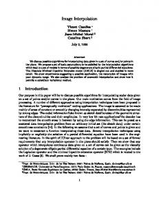
Fig.3 Sampling function of starfish 2.2 Two-dimensional sampling function Based on the one-dimensional sampling function, the twodimensional sampling function is configured upon distance from sampling point, and defined as follows:
ξ ( x, y )= [ s 3]ψ ( x 2 + y 2 )
3 [s]
Here,
ψ (t )
3 [s]
(1)
is a one-dimensional sampling function
which is used in bicubic convolution. This way, original sample points will equally affect the points that are equidistantly located from them. The form of sampling function is shown in Fig.1. In the literature [5], subjective evaluation has been done by comparing with the images converted by the conventional method. 2.3 Adaptively transformed sampling function In the methods mentioned above, the important issue that must be considered is appearing of jaggy edges. Jaggy edges appear due to the use of a single uniform interpolation function. In the method of using adaptively transformed sampling function [6], interpolation is performed using a two-dimensional function whose shape
is transformed along the edge of the image. We call this transformed function as Starfish. In starfish, two-dimensional sampling function is transformed with eight parameters as shown in Fig.2. Three-dimensional view of the starfish is shown in Fig.3. The algorithm of this method is as follows: To determine the shape of the sampling function, the influence from the surrounding sampled pixels to the objective interpolated pixel is calculated. At first, reduction rates toward the surrounding eight pixels are calculated. The shape of the function to each direction is reduced when an edge exists between the objective pixel and its neighbouring pixel. Thus, the transformation ratio for each axis is determined from the values of eight neighbouring sampled pixels. In this process, the global edge shape is not yet considered. The edge direction determined is based only on its local information, and does not always match the global edge shape. The next step is to determine the globally adequate transformation. This is done by incorporating the transformation ratio of each neighbouring pixel to the objective pixel iteratively. In our laboratory, we implement this method and apply to actual image data. The result is compared with images reconstructed by two-dimensional sampling function. In adaptively transformed sampling function method, the jaggy edge is not conspicuous because an edge is enlarged smoothly compared with an image enlarged with twodimensional sampling function. However, this method requires large amount of computation. In addition, the transformation of the sampling function with this method is not necessarily optimal.
3. Enlargement with artificial neural networks In this section, interpolation method using Artificial Neural Networks(ANN) [7] is presented. Proposed method requires less computation, which can be applied to moving pictures. Using high resolution image on network training, optimal image interpolation can be achieved as well in proposed method. ANN is introduced briefly in the subsection that follows, then, the implementation of the image enlargement system using ANN is described. 3.1 Artificial neural networks ANN is an artificial network, which imitate living body neuron, and has been guaranteed that any type of functions can be approximated with high accuracy. There exist many types and architectures of ANN, e.g. Perceptron, RBF, or self-organizing map. In this paper, we focus on multilayer feedforward network structures. The neuron is a fundamental unit to operate ANN. Fig.4 shows a mathematical model of a neuron with N inputs.
x1 , x 2 ,...., x N are the input signals; w1 , w2 ,...., w N are the synaptic weights of neuron; S is the signal after summing up inputs and weights; and y is Here,
the output signal of the neuron. Neurons can be described mathematically by the following set of equations:
from original image(shown as black circles in the figure (c)). This set of 64 pixels and four pixels is a pattern of a training set. Then, as shown in the figure (d), the next training pattern is generated in the same way as described above. After generating all patterns of a training set, they are saved as a TS file.
x1
N
S = ∑ xi wi
(2)
y = f (S − θ )
(3)
i =1
・ ・・
1 1 + e −αz
w2
x2
Here, θ depicts threshold value, and f is some activation function. The activation function is generally nonlinear. In general, sigmoid function is used as shown below:
sigmoid ( z ) =
w1
y
s
wN
xN Fig.4 Artificial neuron
(4)
x1 x2
1) Generating training set In the method using starfish function, the transformation ratios for the interpolated pixel are determined by the neighbouring 64(8x8) sampled points. Thus, in this section, it is assumed that the number of network input is 64(8x8) as a example. Fig. 7 shows the process of determining a training set from an original image when the image is enlarged doubly. The outline of generating the training set is as follows. The first figure(Fig. 7(a)) shows the original image for training and white circles depict the pixels. At first, 64 pixels indicated by gray circles are selected for network inputs(Fig. 7(b)). As the correct values, which is to be compared with output values, four pixels are selected
・ ・・ ・
In this section, we will describe the detail of the implementation. Fig.6 shows the flow chart of the image enlargement system using ANN. As shown in the figure, the system consists of five parts of processes indicated by rectangles, and data files indicated by dotted rectangles. The detail of each process in the figure will be described below.
・ ・・ ・
3.2 Implementation
O
y1
xN
y2
yP
network inputs and y1 , y 2 ,...., y P depict the network outputs, respectively. The layers are indicated as I , H , and O . The number of l depicts the number between each layers and i means the number of neuron in each layer. In this algorithm, each time a training for a pattern is finished, synaptic weights are updated.
H
I
・ ・・ ・
The objective of training such a neural network is to determine the synaptic weights to produce final outputs as close to the target values as possible for all training patterns. Fig.5 shows the model of feedforward network. In this paper, we use backpropagation algorithm [8], which is the most common algorithm for multilayer feedforward network training. In the figure, x1 , x 2 ,....x L depict the
l =1
l=2
Fig.5 Feedforward network 2) Network training For training, the gradient descent algorithm is used. The detail of the algorithm can be found in [9]. In this process, TS file, which is created in previous process is used as a training set. After training, network status with synaptic weights is saved as a WT file . 3) Estimating and interpolation The pixels to be interpolated in the enlarged image are estimated using trained network. In this process, the image is separated into Red, Green, and Blue planes, and estimated individually using the same trained network. Finally, RGB planes are integrated to form a 24-bit bitmap image and saved as an IMG file. As a result, the image is enlarged doubly.
4. Experiment In this section, we will describe the detail of the experimentation using ANN. The image for training, network architecture, and the original images are shown. 4.1 Image for training In training ANN, we used a bicycle image as shown in Fig.8. The image is greyscale, and consists of 332x420 pixels.
bitmap image for training
generating training set TS file network training WT file
bitmap image for enlargement
making estimating set ES file estimation IMG file (RGB)
enlarged bitmap image
Fig.8 Image for using learning
making image
Fig.6 Process of enlargement system with ANN
(a)whole (a)wholebicycle bicycle
(a)
(b)lobster (b)lobster
Fig.9 Original images
(b)
5. Evaluation In this section, we will evaluate the network architecture and quality of the interpolated image. (c)
(d)
Fig.7 Process of generating training set
5.1 Network architecture
4.2 Network architecture
In the network evaluation, the image is enlarged doubly with various parameters to find the optimal network architecture for image interpolation. The original image is “whole bicycle” shown in Fig.9(a).
The architecture of the ANN consists of three layers, an input layer, a hidden layer, and an output layer. To change the area size that affects to interpolated points, the number of neurons of an input layer is varied as 16(4x4), 36(6x6), and 64(8x8). For each case, one extra input is added for bias. The output layer consists of four neurons. The number of neurons in the hidden layer is varied as 40, 45, and 50. The activation function we used is sigmoid function in both hidden layer and output layer.
1) Input layer The image is enlarged doubly with 16, 36, and 64 neurons in input layer, with the 45-neurons hidden layer. The results of interpolation with each parameter are shown in Fig.10. The figures show a part of the resulting image. The results show that the noise is observed in the images interpolated with 16 neurons input and 64 neurons input, while the result with 36 neurons yields less noise compared with others. It has been confirmed that input of 36 neurons is optimal for image interpolation.
4.3 Original image
2) Hidden layer In this evaluation, the image is enlarged using the network with 40, 45, and 50 neurons in hidden layer. The number of input neurons is 36. The parts of result images are shown in Fig.11. Comparing with the image interpolated by the network with 40-neurons in hidden layer, jaggy edges are less conspicuous by the networks with 45-neurons. 50-neurons
JIS(Japan Industrial Standard) full color images, shown in Fig.9 are used as the original images. We used two kinds of images; “whole bicycle” and “lobster”. The size of “whole bicycle” is 616x772 and “lobster” is 492x316, respectively. As described in the section 4.1, the training is performed using a part of the original image “whole bicycle” as shown in Fig. 8.
network produces a image with almost the same quality as the one with 45-neurons. Thus, 45-neurons hidden layer is appeared to be optimal.
As a future work, more extensive experiments using various kinds of images are important to confirm the effectiveness of our method. In addition, we are planning to design a hardware in order to apply the proposed method to video images.
References:
input=16
input=36
input=64
Fig.10 Interpolation results with hidden=45
hidden=40
hidden=45
hidden=50
Fig.11 Interpolation result with input=36 5.2 Image quality In this evaluation, quality of the images enlarged by bicubic convolution, two-dimensional sampling function, starfish function, and the proposed method are compared. The results of interpolation are shown in Fig.12 and Fig.13. The figures show a part of the resulting images. The results show that jaggy edges are observed in the images interpolated by bicubic convolution and twodimensional sampling function. Although the starfish produces less jaggy images than the above conventional methods, smoothest edges are observed in the enlarged images by the proposed method. It has been confirmed that the proposed method can interpolate with higher quality than the conventional method in the edge parts as well as the texture parts of the image.
6. Conclusion This paper presents a new method of image interpolation using an artificial neural network. The proposed method requires less computation than the conventional highquality image interpolation methods. The algorithm of the proposed method was described in detail. To evaluate our method, the proposed method is implemented and applied to actual images. The optimal network architecture is discussed by comparing the quality of the images enlarged by various networks. The results show that our method can produce high-quality enlarged images.
[1] Andrew S.Glassner, ”Principles of Digital Image Synthesis vol.1”, Morgan Kaufmann Publishers, 1995. [2] S.K.Park, “Image Reconstruction by Parametric Cubic Convolution”, Computer Vision, Graphics, and Image Processing, Academic Press, Vol.23, pp258-272, 1983. [3] D.P.Mitchel and A.N Netravali, “Reconstruction Filter in Computer Graphics”, ACM Computer Graphics. Vol.22, No.4, pp.221-228, 1988. [4] C.E.Shannon, “A mathematical theory of communication”, Bell System Tech. J., vol. 27, pp. 379423, 623-656, 1948. [5] H.Aokage, K.Wada, and K.Toraichi. “High Quality Conversion of Image Resolution Using Two-Dimensional Sampling Function”, Proc.of IEEE Pacific Rim Conf. on Communication, Computers and Signal Processing, pp 720-723, 2003. [6] M.Ohira, K.Mori, K.Wada and K.Toraichi, “High Quality Image Restoration by adaptively Transformed Sampling Function”, Proc. of IEEE Pacific Rim Conf. on Communications, Computers and Signal Processing, pp. 201-204, 1999. [7] S.Shekhar and M.B.Amin, “Generalization by Neural Networks”, IEEE Transactions on Knowledge and Data Engineering, vol. 4, no. 2, pp. 177-185, April 1992. [8] Z.Y.Chen, M.Desai and X.P.Zhang, “Feedforward Neural Networks with Multilevel Hidden Neurons for Remotely Sensed Image Classification”, Proc.of the 1997 International Conference on Image Processing, pp. 653655, 1997. [9] F.Diotalevi, M.Valle and D.D.Caviglia, “Evaluation of Gradient Descent Learning Algorithms With an Adaptive Local Rate Technique for Hierarchical FeedForward Architectures”, Proc. of the IEEE-INNSENNS International Joint Conference of Neural Networks, pp.2185-2190, 2000.
(a)bicubic
(b)two-dimensional sampling function
(c)Starfish
(d)ANN Fig.12 lobster
(a)bicubic
(b)two-dimensional sampling function
(c)Starfish
(d)ANN Fig.13 whole bicycle