power in the Power Spectral Density (PSD) concentrates at peaks located at ... paper we propose the application of fluid coding to multiple access for UWB low ...
IEEE International Symposium on Circuits and Systems Circuits and Systems ISCAS 2006, Island of Kos, Greece, May 21-26, 2006.
Application of Fluid Time Hopping Coding to Multiple Access in Ultra Wide Band Sensor Networks Guerino Giancola, Daniele Domenicali, Maria-Gabriella Di Benedetto School of Engineering, University of Rome La Sapienza Infocom Department, Via Eudossiana, 18 – 00184 Rome, Italy email: {giancola, dome, dibenedetto}@newyork.ing.uniroma1.it Abstract— Time Hopping Impulse Radio commonly encodes data symbols by shifting the position of transmitted pulses over a time gap that is quantized within the inter pulse interval range. In this paper, we adopt a previously investigated coding scheme that considers real-valued codes, and as such introduces time hopping in a “fluid” way. We analyze the application of fluid time hopping to UWB sensor networks. For this purpose we consider a fluid time hopping implementation that is simplified to the maximum extent, in order for it to be appropriate for those networks that need a flexible and easily adjustable multiple access scheme. Fluid time hopping proves in fact to allow fast, detailed, and low-complexity spectrum management, as most suitable in self-organizing networks.
performance of fluid TH vs. standard TH coding, by computing the Bit Error Rate (BER) at each active receiver. The paper is organized as follows. Section II summarizes the signal format and the novel technique of fluid TH. Section III analyzes the application of fluid TH to multi-user communications in a specific scenario and comparison of performance with standard TH coding is analyzed by simulation. Section IV contains a discussion and the conclusions. SIGNAL FORMAT
II.
The IR-UWB-TH signal s(t) can be expressed as follows: +∞
I.
INTRODUCTION
s(t ) = ∑ p ( t − jTs − c j Tc − a j ε )
(1)
j =−∞
The main focus of this paper is on Impulse Radio-Ultra Wide Band with Time Hopping coding. Common implementations of such a transmission scheme foresee the adoption of codes with periodicity coinciding with the bit repetition interval. The resulting signal is then periodic with a period equal to the bit repetition interval, and therefore power in the Power Spectral Density (PSD) concentrates at peaks located at multiples of the bit repetition frequency [1][4]. As analyzed in [4] a decrease in the energy concentration at peaks can be obtained by allowing each pulse to assume random positions inside each pulse interval, something that cannot be obtained by simply increasing the periodicity of the TH code. The work in [4] introduces a coding scheme that considers real-valued codes, and as such introduces TH in a fluid way. Based on the analysis of [4], in the present paper we propose the application of fluid coding to multiple access for UWB low data-rate networks. We consider a fluid time hopping implementation that is simplified at most in order for it to be appropriate for those networks that need flexible and easily adjustable multiple access schemes. In order to test and evaluate the proposed fluid TH scheme we introduce a scenario of application, and proceed by simulation. The adopted scenario foresees the presence of multiple users in a given geographical area. All users are in visibility and all active users and transmit at same fixed power and at a data rate in the order of a few Mbits/s. Each user is identified by a specific code. We analyze the
where Ts is the pulse repetition period, p(t) is the impulse response of the pulse shaper, cj is the code value for pulse j, Tc is the chip time, aj is the data symbol, ε is the PPM shift Note that the bit interval Tb is: Tb = NsTs, where Ns is the number of transmitted pulses per bit. Also note that in Eq.(1), the term cjTc defines pulse randomization or dithering with respect to multiples of Ts. We represent cjTc by a random TH dither ηj that can be assumed to be distributed between 0 and Tη < Ts–Tm–ε, where Tm is the duration of the pulse, and we obtain: s (t ) =
+∞
∑ p ( t − jT
j =−∞
s
− η j − a jε )
(2)
The global effect of ηj and ε is to introduce a random time shift, distributed between 0 and Tη+ε < Ts–Tm, which will be indicated by θj leading to the following expression for the transmitted signal: +∞
s(t ) = ∑ p ( t − jTs − θ j )
(3)
j =−∞
Suppose now to substitute in Eq.(1) the discrete-valued cjTc term by a real value Cj defined in the interval [0,Ts − Tm − ε]. The signal of Eq.(1) becomes:
s( t ) =
∞
∑ p( t − jT
j = −∞
s
− C j − a jε )
(4)
As obvious, there exists a variety of possible choices for the analogue waveform that generates the fluid code. A simple fluid TH generator may consist in a sine wave C(t) expressed as:
C (t ) =
(Ts − Tm − ε ) [1 + sin(2πf 0t + ϕ )] 2
(5)
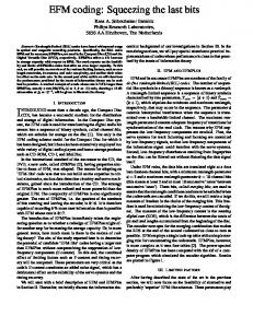
where the period of the sine wave 1/f0 coincides with the period of the code NpTs, that is f0=1/(NpTS). Phase φ falls in the interval [0,2π]. We call function C(t) the “code function” and plot an example of it in Fig.1. Figure 1 shows in the upper plot the sine wave for a fixed set a parameter values, with the sampling instants located at multiples of Ts. The lower plot of Fig.1 shows the sequence of pulses that are shifted according to the sampled values of the sine wave that form the fluid coding values. x 10
-160 -180 -200 -220 -240 -260 -280 -300
0.6 0.4 0.2
0
1
2
3
4
5
6
7 -8
x 10
1.5
4 6 Frequency [Hz]
8
10 x 10
9
-140 -160 -180 -200 -220 -240 -260
-300 0.5
0
1
2
3
4
5
6
1
2 3 Frequency [Hz]
4
5 x 10
7
-8
x 10
Figure 1. The upper plot shows a possible code function represented by a sine wave for Ts=10 ns, Np=3. The sampling times at multiples of Ts are highlighted. The lower plot shows the train of pulses of a generated signal. Pulse positions are shifted by a fluid value provided by the samples of the code function.
The generic element Cj of the code is in the sinewave case expressed by:
C j = C ( jTs ) =
0
Figure 3. Zoom of Figure 2: Power Spectral Density of a UWB signal g2, with fluid sinusoidal TH coding (TS = 25ns and NP = 5).
7
(Ts − Tm − ε ) [1 + sin(2πf 0 jTs + ϕ )] 2 )
Figures 4 and 5 represent the PSD of a signal g2, which adopts a sinusoidal TH code with the same TS value of signal g1, but with an increased value for NP, which is now NP =7. In this case, the code repetition period is NPTS = 175ns, and spectral lines are thus equally spaced by 5.71 MHz. Similarly to the case of signal g1, spectral peaks are about 20dB higher than the continuous part of the PSD. Figure 5 is a zoomed-in plot of the lower part of the PSD.
(6
Cj is real and in the interval [0,Ts − Tm − ε]. Note that in case of multi-user communications each user can be assigned with different f0 or φ value. APPLICATION OF FLUID TIME HOPPING TO MULTIUSER COMMUNICATIONS
Figures 2 and 3 represent the PSD of a signal g1, that adopts a sinusoidal TH code with TS = 25 ns and NP = 5. In this example, the code repetition period is NPTS = 125 ns, and spectral lines are thus equally spaced by 8 MHz. Note that
-100 -120 Power Spectral Density [dBm/Hz]
0
Time [s]
III.
2
-280
1
-0.5
0
Figure 2. Power Spectral Density of a UWB signal g1, with fluid sinusoidal TH coding (TS = 25ns and NP = 5).
Power Spectral Density [dBm/Hz]
Code Function
-140
-120
Time [s]
Pulse Amplitude
-120
-100
0.8
0
-100
Ts=10ns, Np=3
-8
1
spectral peaks are about 20dB higher than the continuous part of the spectrum. Figure 3 is a zoomed-in plot of the lower part of the PSD.
Power Spectral Density [dBm/Hz]
In both fluid and discrete cases, codes may be periodic of period Np.
-140 -160 -180 -200 -220 -240 -260 -280 -300
0
2
4 6 Frequency [Hz]
8
10 x 10
9
Figure 4. Power Spectral Density of a UWB signal g2, with fluid
sinusoidal TH coding (TS = 25ns and NP = 7).
A. Scenario of application
-220 -240 -260 -280 -300
0
1
2 3 Frequency [Hz]
4
5 x 10
7
Figure 5. Zoom of Figure 4: Power Spectral Density of a UWB signal g2, with fluid sinusoidal TH coding (TS = 25ns and NP = 7).
Power Spectral Density in logarithmic units
-100 NP = 7
-120
NP = 5
-140 -160 -180 -200 -220 -240 -260 -280 -300
0
1
2 3 Frequency [Hz]
4
5 x 10
7
Figure 6. Comparison of the Power Spectral Density of signals g1 (gray
TX 3
Figure 6 compares the two PSDs of signals g1 and g2. Here, we observe that the spectral peaks of the two signals are located at different frequencies. Thus, we expect a reduction of interference between different devices operating over the same bandwidth when proper assignment of code periods among different transmissions is implemented. Note that the manifestation of the spectral peaks at different frequencies is sufficient but not required condition for reducing Multi User Interference (MUI) at the intended receiver. For example, the selection of two codes C1(t) and C2(t) as in (5), with identical f0 values, could still result in a reduced MUI thanks to a proper selection of the phases φ1 and φ2. In this case, however, code design requires the knowledge of the propagation time of each signal over the air interface. Such information is not necessary when separating transmissions by different f0 values, with a consequent reduction in complexity for the system. This multiple access scheme will be analyzed in the next section.
TX
2
T
RX 5
As shown, in the case of sinusoidal code function, the PSD is characterized by spectral lines occurring at multiples of f0=1/(NpTS). As a result, given a pulse repetition period TS, power concentration in the PSD can be easily governed by proper selection of code period NP.
RX4 X1
RX 3
-200
TX 5
Power Spectral Density [dBm/Hz]
-180
2
-160
Multiple access and network coexistence can be investigated using a variety of possible topologies, each one capable of underlying different aspects of the system under examination. Though aware of this wide range of different possibilities, our choice is to consider a particular topology, the ring topology, capable of providing a strong inner symmetry and a sort of worst case for the receivers involved as shown in Fig.7. The nodes forming the ring represent alternately a receiver and a transmitter; each transmitter is associated to the receiver diametrically opposed. In this way each receiver is put in a critical situation with respect to the received useful power and also from MUI point of view related to the presence of dominant interferers.
RX
-140
TX4
-120
1 RX
-100
Figure 7. Ring topology including 10 nodes: nodes are alternately transmitters and receivers. Each transmitter is associated to the receiver diametrically opposed.
B. Simulation Results Two different ring topologies were considered. The first includes 10 nodes (5 transmitters and 5 receivers) while the second one includes 6 nodes (3 transmitters and 3 receivers). Both topologies were characterized by a radius of 10 meters and by the following settings: the power of each transmitter was set at 1 mW; the pulse repetition period Ts was set at 30 ns; the chip time value Tc for the standard TH case was set at 5 ns; the waveform had a duration of approximately 1 ns; the shift introduced by PPM was set at 2 ns; each transmitter had a different code periodicity Np. A different code periodicity Np is applied to each active user in both standard and fluid TH coding. The pulse was identical for all transmitters with a typical shape of the second derivative of the Gaussian. For both standard and fluid TH, we considered asynchronous networks, that is, all signals were generated with independent random phases uniformly distributed in the frame time TS. Each topology was studied for different values of number of pulses per bit Ns. In particular the performance of the ring topology containing ten nodes was evaluated for five Ns values equally spaced between 2 and 10, while the ring topology with six nodes was examined for Ns assuming five values from 2 to 6. The choice of two different sets of values for Ns is motivated by the fact that the
two topologies considered are characterized by a different MUI situation. For the topology including six nodes, 5 or 6 pulses per bit were in fact sufficient to achieve satisfying BER values for the fluid coding case. Note that increasing the number of pulses per bit results in a decreased bit rate and in an increased energy transmitted per bit. The Signal to Interference Ratio (SIR) also increases when Ns increases; in fact, when SIR is evaluated, the useful contribution rises in a quadratic way with respect to Ns, while the interfering contribution rises in a linear way. With respect to signal propagation, a basic AWGN channel model (multipath-free) is considered for the simulation. The effect of multipath propagation will be the object of future investigations. Results obtained for the ring topology including ten vs. six nodes are shown in Figs.8 and 9, respectively. 10
Bit Error Rate
10
10
10
-1
-2
-3
ACKNOWLEDGMENT
-4
Standard TH Fluid TH 10
-5
Ns = 2 (Eb = 2 Ep)
Ns = 4 (Eb = 4 Ep)
Ns = 6 (Eb = 6 Ep)
Ns = 8 (Eb = 8 Ep)
Ns = 10 (Eb = 10 Ep)
Figure 8. BER vs. Ns in the two cases of standard TH coding (full line and triangles) and Fluid TH coding (dotted line and losangues) for the same ring topology (radius = 10 m and 10 nodes). Transmitted energy per bit Eb is also indicated for convinience as a multiple of the energy per pulse Ep=1.49·10−18J
Bit Error Rate
10
10
10
DISCUSSION AND CONCLUSION IV. In this paper, we analyzed the effect of relaxing the hypothesis of a discrete chip-time on performance of an UWB network adopting TH codes for multiple access. We considered a network of asynchronous binary TH-PPM UWB devices using same TS. Each active link uses a specific fluid code known at both transmitter and receiver. Codes were generated by selection of a different period and random phase of a sine wave for each active link of the network. In this way, spectral peaks of different signals are located at different frequencies. We focused the analysis on the effect of MUI in the case of a ring topology of nodes where all nodes were in identical MUI conditions. Results indicated that by fluidizing the code a significant improvement in system performance can be obtained. These results should be considered as a first ground where fluid TH proves to be effective. One concern that may arise is related to the analogue nature of code values that may require an increase in complexity of receiver design [5]. In order to solve this question we would like to suggest that the use of analogue correlation and detection might prove to be a feasible way out in the case of low data rate networks. This issue will be the object of future investigation.
This work was partially supported by the European Union under the 6th Framework Network of Excellence HYCON (contract number FP6-IST-511368) and of Integrated Project P.U.L.S.E.R.S. (project no. 506897). REFERENCES [1]
-2
[2]
-3
[3]
-4
[4] Standard TH Fluid TH
10
-5
Ns = 2 (Eb = 2 Ep)
Ns = 3 (Eb = 3 Ep)
Ns = 4 (Eb = 4 Ep)
Ns = 5 (Eb = 5 Ep)
Ns = 6 (Eb = 6 Ep)
Figure 9. BER vs. Ns in the two cases of standard TH coding (full line and triangles) and Fluid TH coding (dotted line and losangues) for the same ring topology (radius = 10 m and 6 nodes). Transmitted energy per bit Eb is also indicated for convinience as a multiple of the energy per pulse Ep=1.49·10−18J
[5]
Kissick, A. “The temporal and Spectral Characteristics of Ultrawideband Signals”, 2001, NTIA Report 01-383, U.S. Department of Commerce. Win, M.Z., “Spectral Density of Random Time-Hopping Spread Spectrum UWB Signals with Uniform Timing Jitter,” in Proceedings of the IEEE Military Communications Conference, 1999 (MILCOM 1999), pp. 1196-1200. Win, M.Z., “A Unified Spectral Analysis of Generalized TimeHopping Spread Spectrum Signals in the Presence of Timing Jitter,” in IEEE Transactions on Selected Areas in Communications, 20(9): 1664-1676. Di Benedetto, M.-G.; Giancola, G; Domenicali, D.; Ingargiola, P., “Fluid Coding in Time Hopping Ultra Wide Band Networks,” in Proceedings of the IEEE 2nd International Workshop Networking with Ultra Wide Band - Ultra Wide Band for Sensor Networks, 2005, Rome, Italy. Nakache, Y-P; Molisch, A.F., "Spectral Shape of UWB Signals Influence of Modulation Format, Multiple Access Scheme and Pulse Shape", /IEEE Vehicular Technology Conference (VTC)/, ISSN: 1090-3038, Vol. 4, pp. 2510-2514, April 2003