ically very fragile to post-decoding residual errors. At the receiver, a ... scheme. The ratio b = n/k (channel uses per source symbol) is commonly referred to.
2009 Data Compression Conference
Joint Source-Channel Coding at the Application Layer 1
O. Y. Bursalioglu1, M. Fresia2 , G. Caire1 , and H. V. Poor2 Ming Hsieh Dept. of Electrical Engineering, University of Southern California, Los Angeles, CA. 2 Dept. of Electrical Engineering, Princeton University, Princeton, NJ.
Abstract The multicasting of an independent and identically distributed Gaussian source over a binary erasure broadcast channel is considered. This model applies to a one-to-many transmission scenario in which some mechanism at the physical layer delivers information packets with losses represented by erasures, and users are subject to different erasure probabilities. The reconstruction signal-to-noise ratio (SNR) region achieved by concatenating a multiresolution source code with a broadcast channel code is characterized and four convex optimization problems corresponding to different performance criteria are solved. Each problem defines a particular operating point on the dominant face of the SNR region. Layered joint sourcechannel codes are constructed based on the concatenation of embedded scalar quantizers with binary raptor encoders. The proposed schemes are shown to operate very close to the theoretical optimum.
I. I NTRODUCTION Multimedia streaming to wired and wireless/mobile users is one of the most important and rapidly growing applications in the modern Internet. A conventional approach consists of establishing individual streaming sessions from the server to each user. This may be very inefficient when many users wish to receive the same content at the same time (e.g., in mobile television applications). In contrast, conventional analog broadcasting systems send simultaneously the same signal to a potentially unlimited number of receivers, with possibly different reconstruction quality that depends on the channel conditions. In order to achieve such scalability and “graceful degradation” in a digital network, in this paper we consider a system in which the server generates coded information packets that are multicast to an arbitrarily large number of users. We disregard the details of the physical, link and network layers of the underlying heterogeneous network and model the system, seen at the application layer, as an erasure broadcast channel [1]. To cope with erasures at the application layer, Forward Error Correcting (FEC) codes are considered [2]. We consider an idealized information-theoretic model for the above scenario (see Section II), we investigate its fundamental limits, and provide explicit code constructions that perform remarkably close to the limits with low complexity. In previous work [3], [4], we proposed a class of joint source-channel codes (JSCCs) for the end-to-end quadratic distortion criterion based on the concatenation of transform coding, scalar quantization, and linear channel coding. The latter maps directly the redundant quantization bits onto channel-encoded symbols, eliminating the need for an entropy coding stage, which is typically very fragile to post-decoding residual errors. At the receiver, a Belief-Propagation (BP) iterative decoding algorithm combines the a-priori source probability distribution The research was supported in part by the National Science Foundation under Grants CNS-06-25637 and CNS-0722073.
1068-0314/09 $25.00 © 2009 IEEE DOI 10.1109/DCC.2009.10
93
Authorized licensed use limited to: University of Southern California. Downloaded on November 30, 2009 at 15:15 from IEEE Xplore. Restrictions apply.
with the observed channel output and produces soft log-likelihood ratios (LLRs) for the quantization bits, which are then used for robust soft-bit reconstruction. Here we extend our JSCC scheme to the case of multicasting over the broadcast erasure channel. We use multi-resolution (embedded) quantization and layered JSCC, in order to serve simultaneously several users at different channel capacities (i.e., different erasure probabilities). The allocation of source layers to different users can be optimized according to different criteria, as discussed in Section III. Performing close to the theoretical limits requires coding rate adaptation with very fine granularity. In the proposed scheme (see Section IV), this is accomplished by using raptor encoders [5], which are able to produce any arbitrary number of coded symbols “on demand” with a single, low complexity, encoding machine. Recently, raptor codes [5] have been standardized as application layer FEC coding for Multimedia Broadcast/Multicast Services (MBMS) within 3GPP [6]. We hasten to say that our application is very different from this standard. In 3GPP [6], the “static broadcasting” [7] of a common content file is considered, where each user gathers enough channel observations until it has received enough non-erased symbols such that the whole file can be perfectly decoded. Users may have different decoding delays depending on their erasure probabilities. In contrast, in this work we consider a truly “real-time” multicasting where the decoding delay is the same for all users, but each user reconstructs the source at a possibly different distortion level, depending on its own channel capacity. The numerical results of Section IV show that the proposed coding scheme can achieve end-to-end distortion performance very close to the theoretical limits with finite block length and low encoding/decoding complexity. II. G AUSSIAN S OURCE OVER B INARY E RASURE B ROADCAST C HANNEL The Binary Erasure Broadcast Channel (BEBC) has input alphabet {0, 1}, output alphabet {0, 1, e}, where “e” denotes an erasure, and is defined by L channel transition probabilities P (l) (y|x) = 1 − �l for y = x, P (l) (e|x) = �l for y = e and P (l) (y|x) = 0 for y �= x, e, where L is the number of the different binary erasure channels (BEC) considered. Without loss of generality, we let �1 ≥ . . . ≥ �L and denote by Cl = 1 − �l the capacity of the l-th binary erasure channel (BEC). This channel serves as a simple model for a multicast network where an arbitrarily large number of users are grouped into L classes, with different channel qualities characterized by their erasure probabilities. For simplicity, we shall refer to each class as a “user” since, in a multicast scenario, all users belonging to the same class are indistinguishable and achieve the same performance. We consider the transmission of an i.i.d. Gaussian source vector S ∈ Rk , with components Si ∼ N (0, 1). The encoder maps S into X = f (k) (S), where f (k) : Rk → {0, 1}n is a suitable encoding function. At each l-th user decoder, the received channel output Yl � l = g (k) (Yl ), where g (k) : {0, 1, e}n → Rk is mapped into a reconstructed source vector S l l (k) is a suitable decoding function. We define the average quadratic distortion Dl = 1 �l �2 ], where the expectation is with respect to the joint k-dimensional probability E[�S− S k �l ) induced by the source, by the channel erasures and by the coding distribution of (S, S scheme. The ratio b = n/k (channel uses per source symbol) is commonly referred to as the “bandwidth expansion” factor of the system. The reconstruction signal-to-noise (k) (k) (k) ratio (SNR) is defined as SNRl = −10 log10 Dl , where Dl is the distortion for the 94
Authorized licensed use limited to: University of Southern California. Downloaded on November 30, 2009 at 15:15 from IEEE Xplore. Restrictions apply.
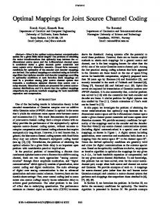
Figure 1. A multiresolution source encoder creates 3 layers with SNR1 < SNR2 < SNR3 for three classes of users with capacities C1 ≤ C2 ≤ C3 . The multicast scheme is designed such that each user receives an extra layer with respect to previous user. The channel encoder-decoder pair at rate C is shown as blocks CE(C) and CD(C), respectively, in the figure.
lth layer. For given b, a SNR L-tuple (SNR1 , . . . , SNRL ) is achievable if there exists a (k) (k) sequence of coding schemes (f (k) , g1 , . . . , gL ) such that n = bk and, as k → ∞, (k) SNRl → SNRl for all l = 1, . . . , L. The achievable SNR region of the system is the closure of the convex hull of all achievable SNR L-tuples. It is well-known that, under mild conditions on the erasure statistics1 the capacity region of the BEBC is given by [1] �
C = (R1 , . . . , RL ) : Rl ≥ 0,
L � Rl l=1
Cl
�
≤ 1, l ∈ {1, . . . , L} .
(1)
It is seen immediately that this region is achieved by time-sharing between the individual capacities of�each user. In fact, the vertices of the region’s dominant face, defined by the l hyperplane Ll=1 R = 1 are the points cl = (0, . . . , Cl , . . . , 0). The BEBC belongs to the Cl class of stochastically degraded broadcast channels [8]. With degradation order defined by �1 ≥ . . . ≥ �L , this implies that any message to user l can be also decoded by all users j > l (with better channels). Building on [1], we can give an explicit characterization of the SNR region for the BEBC achieved by the layered architecture shown in Fig. 1. An ideal (rate-distortion achieving) multiresolution source code produces L layers at rates R1� , . . . , RL� bits per source symbol (See Fig. 1). The L layers are encoded by a broadcast code for the BEBC at rates (R1 , . . . , RL ) ∈ C. By definition of b, the channel coding rate and the source coding rate of layer l are related by Rl� = bRl . Since the Gaussian source is successively refinable [10], these correspond to distortion levels Dl = Pl � 2−2 j=1 Rj , or, equivalently, to SNRs SNRl = �b
l �
Rj
(2)
j=1
(where we define the constant �b = (20 log10 2)b). Since the BEBC capacity region can be achieved by time-sharing, this reduces to successive transmission of the layers such that layer 1 is encoded in the first segment of n1 channel uses, layer 2 in the next n2 1
As a matter of fact, the capacity region of a broadcast channel depends only on the marginal transition probabilities [8], and hence erasures can be arbitrarily correlated. Furthermore, erasures need not be i.i.d. in time; any erasure process such that the fraction of erased symbols converges almost surely to �l for each l = 1, . . . , L yields the same capacity region [9]. 95
Authorized licensed use limited to: University of Southern California. Downloaded on November 30, 2009 at 15:15 from IEEE Xplore. Restrictions apply.
channel uses, and so on. Assuming that each channel code operate at the capacity of the corresponding user, we have segments of length nl = kbRl /Cl . Let P(b, C1 , . . . , CL) denote the region of SNRs achievable with the layered scheme given above. Since C is a polytope and (2) is a linear transformation, also P(b, C1 , . . . , CL) is a polytope. This is defined by the inequalities 0 ≤ SNR1 ≤ · · · ≤ SNRL and by the inequality that determines the dominant face. The vertices {vl } of the dominant face of P(b, C1 , . . . , CL) are obtained by mapping via (2) the vertices {cl } of the dominant face of C, and are explicitly given by v1 = (�bC1 , . . . , �bC1 ), v2 = (0, �bC2 , . . . , �bC2 ), . . . and vL = (0, . . . , 0, �bCL ).
(3)
Any point x on the dominant face of P(b, C1 , . . . , CL ) must satisfy the hyperplane equation uT x = a for a certain constant a. Imposing this condition for all x = vl given in (3) and eliminating the constant a, we can solve for the vector u perpendicular to the dominant face hyperplane, and obtain the inequality that defines the dominant face as � � � SNR1
1 1 − C1 C2
+ SNR2
1 1 − C2 C3
+ . . . + SNRL
1 CL
≤ �b.
(4)
It should be noted that the vertex vl corresponds to transmitting a non-layered sourcechannel coding scheme at the capacity Cl of user l. Therefore, all users l, l + 1, . . . , L receive at the rate-distortion bound of user l, and all users 1, . . . , l − 1, with smaller individual capacity, achieve SNR of 0 dB (i.e., they reconstruct the source as the constant zero vector). As expected, operating at the vertices of the SNR achievable region requires no multiresolution/layered coding scheme. It should also be observed that the P(b, C1 , . . . , CL) is achievable by using the concatenation of multiresolution source coding and time-sharing (also referred to as “progressive transmission”) on any degraded broadcast channel with individual single-user capacities C1 , . . . , CL. III. M ULTICAST S YSTEM O PTIMIZATION Any point on the dominant face of P(b, C1 , . . . , CL) is a Pareto-optimal point that corresponds to the maximization of a certain objective function. The choice of the objective function depends on the scenario considered, which determines an appropriate performance criterion. In this work we shall consider the following four objective functions and solve the corresponding optimization � problems: Max Weighted Total SNR (MWTS): maximize Ll=1 wl SNRl , where {wl } are given non-negative weights, for a given b. � Min Weighted Total Distortion (MWTD): minimize Ll=1 wl Dl , where {wl } are given non-negative weights, for a given b.
� Min-Max SNR penalty (MMS): minimize maxl∈1,...,L SNRopt − SNRl where SNRopt = l l �bCl is the individual rate-distortion bound for user l, for a given b. Min Bandwidth (MB): minimize b, for given SNR constraints, i.e., subject to γ ∈ P(b, C1 , . . . , CL ), where γ ≥ 0 is a vector of target SNRs. Because of space limitation, here we will give only a sketch of the solutions of the above problems. Since P(b, C1 , . . . , CL ) is a polytope, the MWTS problem is immediately given as a linear program and, for all weighting coefficients {wl } the solution is a vertex of P(b, C1 , . . . , CL ). In particular, it is immediate to�see that the �solution is obtained by � choosing the vertex vl∗ such that l∗ = arg maxl∈L Cl Lj=l wj . Since the vertices vl 96
Authorized licensed use limited to: University of Southern California. Downloaded on November 30, 2009 at 15:15 from IEEE Xplore. Restrictions apply.
can be achieved by standard single-layer coding, this problem does not lead to interesting code design and shall not be considered in the following. The MMS problem can be equivalently formulated as subject to �bCl − SNRl ≤ t, ∀ l ∈ L {SNRl } ∈ P(b, C1 , . . . , CL).
minimize t,
(5)
This is a linear program that can be solved by standard numerical methods. The MB problem is meaningful only if the target SNR vector γ is compatible with the degradedness of the BEBC, i.e., if it satisfies the inequalities 0 ≤ γ1 ≤ · · · ≤ γL . In this case, we notice that the minimum b is obtained by imposing the condition that γ belongs to the dominant face of P(b, C1 , . . . , CL ). This is obtained explicitly from (4) as � � 1 1 1 1 1 �b = γ1 − − . + γ2 + · · · + γL C1 C2 C2 C3 CL The solution of the MWTD problem is more involved and shall be discussed in the rest of this section. For analytical convenience, we reparameterize the problem and define Δ Δ 1 rl = − log Dl = log1010 SNRl , b� = log1010 �b, r0 = 0 and Δl = C1l − Cl+1 with CL+1 = ∞. Then, the problem is given as minimize
L �
wl exp(−rl ),
subject to 0 ≤ r1 ≤ . . . ≤ rL
l=1 L �
Δl rl = b� .
(6)
l=1
This is a convex optimization problem. By differentiating the associated Lagrangian function Λ, we obtain the following Karush-Kuhn-Tucker (KKT) conditions: � ∂Λ = −wl exp(−rl ) + λΔl − μl + μl+1 = 0, Δl rl = b� , ∂rl l=1 L
� λ Δl rl − b� = 0, μl ≥ 0, λ ≥ 0, 0 ≤ r1 ≤ . . . ≤ rL . L
∀l ∈ L, μl (rl−1 − rl ) = 0,
l=1
The difficulty here is given by the fact that some groups of variables rl with adjacent indices may be equal. Consider the L inequalities 0 ≤ r1 ≤ · · · ≤ rL . Some of them are strict and some hold with equality. There are precisely 2L − 1 such configurations, excluding the configuration of all equalities, which yields the case rl = 0 for all l ∈ L that is clearly not the solution. Although it is not possible to obtain a closed-form solution of the KKT equations for the general case, we notice that for each configuration of the inequalities 0 ≤ r1 ≤ · · · ≤ rL we can find a point for which the gradient of Λ is zero. Therefore, the solution can be found by searching over all 2L − 1 configurations, and checking the consistency of the KKT conditions for each corresponding tentative solution. Since the problem is convex, as soon as a consistent solution is found this is the sought optimal point. Next, we will show how to obtain a tentative solution that annihilates the gradient of Λ assuming a certain configuration of the inequalities 0 ≤ r1 ≤ · · · ≤ rL . Suppose that 97
Authorized licensed use limited to: University of Southern California. Downloaded on November 30, 2009 at 15:15 from IEEE Xplore. Restrictions apply.
0 ≤ r1 ≤ r2 ≤ . . . ≤ rk−1 < rk = rk+1 = . . . = rk+N −1 < rk+N ≤ . . . ≤ rL , for some N and k. From the KKT conditions it follows that μk+i ≥ 0 for 1 ≤ i ≤ N − 1, and μk+i = 0 for i = 0, N. On letting ρk = exp(−rk ) and equating the partial derivatives of Λ to zero, we obtain the system of equations −μk+1 + wk ρk = λΔk μk+1 − μk+2 + wk+1ρk = λΔk+1 .. . μk+N −1 + wk+N −1ρk = λΔk+N −1 . Summing all equations we find
� −1 Δj λ k+N j=k ρk = �k+N −1 . wj j=k
(7)
(8)
Now, assume that we have G + 1 disjoint groups of equal elements rl , where group g = 0 contains the elements equal to zero, and groups g = 1, . . . , G contain non-zero elements. Also, let rkg denote the value of the elements in group g, where kg , kg + 1, . . . , kg + � Ng − 1 is the support of group g and, obviously, G g=0 Ng = L. Similarly to (8), letting �kg +Ng −1 �kg +Ng −1 ρkg = exp(−rkg ), and defining Ag = j=kg Δj and Wg = j=k wj , we obtain g λAg ρkg = Wg . Replacing this into the dominant-face equation, which must hold with equality (otherwise, some of the distortions could be improved), we find �G Ag � � L G � � b + λA g=1 Ag log Wg g � ⇒ − log(λ) = Δl rl = . . . = − Ag log . (9) b = �G W g A g g=1 g=1 l=1 Eventually, for each configuration of the equality groups we can compute λ from (9), g and {μl } using (7), in order to check the KKT conditions consistency. It ρkg as ρkg = λA Wg should not be neglected that a group g = 0 of N0 zero elements 0 = r1 = . . . = rN0 may exist. This yields μ1 , . . . , μN0 ≥ 0, μN0 +1 = 0 and λΔl − μl + μl+1 = 1 for 1 ≤ l ≤ N0 , so that the values of μ1 , . . . , μN0 can be also found. IV. J OINT S OURCE -C HANNEL C ODING FOR THE BEBC In this section we present a practical coding scheme based on embedded scalar quantization and binary raptor codes [5] that closely approaches the theoretical limits of Section III at finite block length and constant encoding/decoding complexity per source symbol. It is well-known that entropy-coded scalar quantization achieves rate-distortion performance within a fixed gap from the optimal limit, for i.i.d. smooth source statistics and quadratic distortion [11]. Furthermore, embedded uniform scalar quantizers that achieve (roughly) a 6dB improvement in the reconstruction SNR for each additional quantization bit are easily designed [12]. Let Q : R → FN 2 denote a scalar embedded quantizer, and let u = Q(S) denote the binary index of length N corresponding to the source symbol S. A source vector S = (S1 , . . . , Sk ) is mapped componentwise into a sequence of binary indices U = [u1 , . . . , uk ], formatted as an N × k binary array. We shall refer to the i-th row of U, denoted by Ui,: , as the i-th “bit-plane”. Without loss of generality, we let U1,: denote the sign bit-plane, and U2,: , . . . , UN,: denote the magnitude bit-planes with 98
Authorized licensed use limited to: University of Southern California. Downloaded on November 30, 2009 at 15:15 from IEEE Xplore. Restrictions apply.
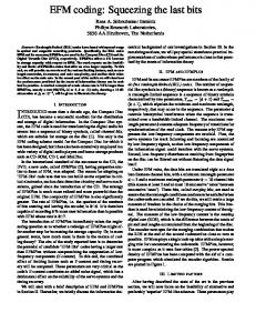
ACHIEVABLE REGION FOR b = 9.5
MWTD MWTS MMS
25
USER 1
20 15 10 5 0 0 20
60 40
40 USER 3
60 0
20 USER 2
Figure 2. The tetrahedron shown in the figure is the achievable SNR region for a BEBC with individual capacities C1 = 0.36, C2 = 0.81, C3 = 0.9 and b = 9.5. The solutions of the MWTS, MWTD (for unit weights) and MMS problems are shown as points on the dominant face. The corresponding points are, respectively: SNR� = [0 46.33 46.33], SNR� = [19 22.98 22.98], SNR◦ = [7.29 32.77 37.92]
decreasing order of significance. The quantizer distortion as a function of the bit-planes is given by DQ (p) = α2−2p for p = 1, 2, . . . , N, where α is a fixed constant (see [13]). For the class of quantizers used in this work we have α ≈ 1.5 as shown in Fig. 3 (a).2 The quantizer output U forms a discrete memoryless source, with entropy H(u) (in units of bits/source symbol) that can be decomposed according to the well-known entropy chain rule. For simplicity of notation, the conditional entropy of bit-plane i given the previous bit-planes will be denoted by Hi = k1 H(Ui,: |U1,: , . . . , Ui−1,: ). The ratedistortion function achieved by embedded scalar quantization followed by entropy coding of�the quantization indices, namely, the set of rate-distortion points with coordinates ( pi=1 Hi , DQ (p)) for p = 1, . . . , N, is close to the Gaussian rate-distortion function (see Fig. 3(a)). It is also well-known that powerful graph-based codes, such as low N = 10
60
SNR
40 SNR (R’) rd
20
SNReq(R’) SNR (R’) α
0 0
2
4
6
8
10
R’
(a)
(b)
Figure 3. (a): Comparison between the reconstruction SNR-Rate trade-offs for Gaussian source obtained by ratedistortion function´(SNRrd (R� )), by the set of rate-distortion points of the embedded quantizer with coordinates `P p � −2R� where α = 1.5; (b): This figure illustrates i=1 Hi , DQ (p) for p = 1, . . . , N (SNReq )) and by DQ (R ) = α2 the rounding of the SNR solutions of the information-theoretic optimization problems to the actual SNRs achievable by the proposed scheme, with corresponding allocation of the bit-planes. 2 Notice that the optimization problems discussed in Section III refer to α = 1 but they can be straightforwardly adapted to different values of α.
99
Authorized licensed use limited to: University of Southern California. Downloaded on November 30, 2009 at 15:15 from IEEE Xplore. Restrictions apply.
density parity check codes (LDPCs) and raptor codes [14], [5], achieve very small biterror probability at rates very close to the capacity of the BEC, with linear encoding and decoding complexity. This suggests that the theoretical optimal performance can be approached by the following general coding architecture: 1- Let {SNRl } denote the desired theoretical operating point on the dominant face of P(b, C1 , . . . , CL), obtained as the solution of the system optimization of Section III. 2- Allocate pl bit-planes (from 1 to pl ) to user l, such that −10 log10 DQ (pl ) ≈ SNRl . Since the quantizer offers only N possible distortion levels, this step requires some suitable rounding of the target SNRl . We set p0 = 0 for convenience of notation. 3- For each l, the block of corresponding pl − pl−1 bit-planes is entropy-coded �pl by any suitable lossless compression algorithm. The corresponding block of Bl = k i=1+pl−1 Hi entropy-coded bits are mapped into a codeword of length nl = Bl /(Cl − δl ) channelcoded symbols, where δl denotes the “gap-to-capacity” of the binary code used at layer l. 4- The �Lchannel encoded blocks are transmitted in sequence, with total block length n = l=1 nl . 5- The lth decoder, sequentially decodes all layer codewords from 1 to l. If the postdecoding error probability is sufficiently low, the source can be reconstructed at the quantizer with reconstruction SNR, −10 log10 DQ (pl ), that is close to the target SNRl by construction. The overall bandwidth expansion factor of the scheme is given by �pl �L L � n i=1+pl−1 Hi �b = l=1 l = . k C l − δl l=1 For a good family of codes, achieving small gap-to-capacity, and an appropriate choice of the bit-plane allocation to the layers, the achieved �b is only slightly larger than the “design” bandwidth expansion factor b. As noticed in [3] and [4], the weak link in the above code construction consists of the entropy-coding stage: since the entropy coding is known to be non-robust to channel errors, in order to approach the quantization distortion, each layer must be decoded with extremely low residual bit-error probability. On one hand, we want to perform close to capacity (small gap δl ). On the other hand, we need to achieve essentially zero bit-error probability at the decoder output. In practice, we wish to make use of modern low-density graph-based codes with BP decoding [5],[15]. With these codes it is easy to achieve biterror probabilities between 10−2 and 10−3 at block lengths between 1000 and 10000. However, these post-decoding bit-error probabilities are completely unsuited for entropy decoding, and this would result in a very large distortion (see [3] for a detailed analysis of the effect of residual channel decoding errors on the end-to-end distortion, when entropy coding is implemented by an arithmetic coding [8] algorithm). A vast literature has dealt with the issue of making entropy coding “robust” to channel errors (see [16], [17], [18] and references therein). Here we shall follow a more radical approach. As proposed in [3], we bypass explicit entropy coding and map directly the redundant quantizer bit-planes onto channel-encoded symbol using a single linear encoding operation. It is well-known that linear coding achieves the entropy-rate of a discrete source. Also, linear coding achieves the capacity of symmetric channels. Since the concatenation of two linear maps (the first for compression and the second for channel coding) is linear, it follows that the limiting performance of ideal lossless compression 100
Authorized licensed use limited to: University of Southern California. Downloaded on November 30, 2009 at 15:15 from IEEE Xplore. Restrictions apply.
Figure 4.
Proposed multicast JSCC scheme for the case of 3 users, N = 6 and p = [3 5 6]. Table I
Problem Type MWTD b = 9.5 MMS b = 9.5
{SNRl }∗ , α = 1 [19.1 22.98 22.98] [7.29 32.77 37.92]
{SNRl }∗ , α = 1.5 [17.34 21.22 21.22] [5.53 31.01 36.16]
designed p p = [4 5 5] p = [2 7 8]
{SNRl }∗J SCC [15.8 21.8 21.8] [3.64 33.8 39.9]
ˆbJ SCC 10.48 11.40
and channel coding can be achieved by a single linear encoding stage. The proposed coding scheme maps each bit-plane Ui,: , for pl−1 < i ≤ pl (i.e., associated to layer l) to a block of channel-coded symbols Xi = Ui,: Gi , where Gi is a k × mi generator matrix of a suitable linear code. This is indicated as the “JSCC encoder” in the block diagram of Fig. 4. The rate of this linear encoder is chosen such that mki is slightly larger than the i . The rate margin must be optimized numerically and it depends on theoretical limit H Cl the block length k, on the capacity Cl and on the actual code construction. The coded block for layer l is obtained by concatenating �pl the codewords [Xpl−1+1 , . . . , Xpl ] for all bit-planes allocated to layer l, so that nl = i=1+pl−1 mi . At the layer-l receiver, all bitplanes 1 ≤ i ≤ pl are decoded in sequence by a multi-stage decoder (“JSCC decoder” in the block diagram of Fig. 4). Each component decoder in the multi-stage decoder is based on the BP algorithm. Details are omitted for the sake of space limitation, and the reader is referred to [3] where the scheme is explained in details. The BP decoder for the bit-plane i incorporates the source a-priori information given by the a-priori probability distribution of the symbols of Ui,: conditioned on the knowledge of the previous bit-planes U1,: , . . . , Ui−1,: . These are obtained from the decoder output of the previous stages in the multistage decoder. The BP iterative decoding algorithm produces soft outputs, in the form of approximated posterior log-likelihood ratios of the bit-plane symbols. This information can be used to reconstruct the quantizer quantization points according to the posterior-mean estimator principle. This yields the well-known soft-bit reconstruction scheme (see [3] and references therein), which further improves the scheme performance with respect to hard-decoding reconstruction. Building on our results in [3], we implement the linear encoders operating on each
101
Authorized licensed use limited to: University of Southern California. Downloaded on November 30, 2009 at 15:15 from IEEE Xplore. Restrictions apply.
Table II
MB γ
[15.79 15.79 15.79] [15.79 21.81 33.84] [21.81 33.84 39.84]
b∗min , α = 1 7.19 10.65 13.51
b∗min , α = 1.5 7.99 11.45 14.31
designed p [4 4 4] [4 5 7] [5 7 8]
ˆbJ SCC 9.07 12.83 15.95
bit-plane via a systematic raptor encoder with degree distribution [5] Ω(x) = 0.008x + 0.494x2 + 0.166x3 + 0.073x4 + 0.083x5 +0.056x8 + 0.037x9 + 0.056x19 + 0.025x65 + 0.003x66 . Raptor codes are particularly suited for this application since they have an efficient systematic encoder (linear complexity) and an efficient BP iterative decoding algorithm that easily incorporates the bit-plane a-priori probabilities. The same basic raptor encoder can be used at each bit-plane, since it can produce an arbitrary number of coded symbols and then adapt the coding rate for any desired ratio Hi /Cl . We report a few simulation result for source block length k = 10000 in Tabs. I and II. In Tab. I, the result for the MWTD and MMS scenarios are shown. The optimal {SNRl }∗ values for each user are given both for α = 1 (rate-distortion limit) and α = 1.5 (scalar quantizers) cases. The allocation of the bit-planes to the layers (expressd by the vector p), is obtained by rounding the optimal SNR values to discrete SNR values of the embedded quantizer (see Fig. 3 (b)), as explained before. R EFERENCES [1] R. L. Urbanke and A. D. Wyner, “Packetizing for the erasure broadcast channel with an internet application,” in Proc. Int. Conf. on Combinatorics, Information Theory and Statistics, Portland, ME, 1997, p. 93. [2] J. Byers, M. Luby, and M. Mitzenmacher, “A digital fountain approach to asynchronous reliable multicast,” IEEE Jour. Sel. Areas in Communications, vol. 20, no. 8, pp. 1528–1540, Oct 2002. [3] O. Y. Bursalioglu, M. Fresia, G. Caire, and H. V. Poor, “Lossy joint source-channel coding using raptor codes,” Int. Journal of Digital Multimedia Broadcasting, vol. 2008, Article ID 124685, 18 pages. [4] M. Fresia and G. Caire, “A practical approach to lossy joint source-channel coding,” January 2007, submitted to IEEE Trans. Inform. Theory. [5] A. Shokrollahi, “Raptor codes,” IEEE Trans. Inform. Theory, vol. 52, pp. 2551 – 2567, June 2006. [6] M. Luby, T. Gasiba, T. Stockhammer, and M. Watson, “Reliable multimedia download delivery in cellular broadcast networks,” IEEE Trans. Broadcasting, vol. 53, no. 1, pp. 235–246, March 2007. [7] N. Shulman and M. Feder, “Static broadcasting,” in Proc. IEEE Int. Symp. Inform. Theory, Sorrento, Italy, 2000. [8] T. Cover and J. Thomas, Elements of Information Theory. New York: Wiley, 1991. [9] T. S. Han, Information Spectrum Methods in Information Theory. New York: Springer Verlag, 2002. [10] W. Equitz and T. Cover, “Successive refinement of information,” IEEE Trans. Inform. Theory, vol. 37, no. 2, pp. 269–275, Mar 1991. [11] H. Gish and J. N. Pierce, “Asymptotically efficient quantizing,” IEEE Trans. Inform. Theory, vol. 14, pp. 676–683, Sept. 1968. [12] B. Tang, A. Shen, A. Alwan, and G. Pottie, “A perceptually based embedded subband speech coder,” IEEE Trans. on Speech and Audio Processing, vol. 5, no. 2, pp. 131–140, Mar 1997. [13] J. Ziv, “On universal quantization,” IEEE Trans. Inform. Theory, vol. 31, no. 3, pp. 344–347, May 1985. [14] T. J. Richardson, M. A. Shokrollahi, and R. L. Urbanke, “Design of capacity-approaching irregular low-density parity-check codes,” IEEE Trans. Inform. Theory, vol. 47, pp. 619–637, Feb. 2001. [15] T. Richardson and R. Urbanke, Modern Coding Theory. Cambridge, UK: Cambridge University Press, 2008. [16] M. Grangetto, B. Scanavino, and G. Olmo, “Joint source-channel iterative decoding of arithmetic codes,” Paris, France, 2004, pp. 886–890. [17] M. Jeanne, J. Carlach, and P. Siohan, “Joint source-channel decoding of variable-length codes for convolutional codes and turbo codes,” IEEE Trans. Commun., vol. 53, no. 1, p. 11, 2005. [18] L. Perros-Meilhac and C. Lamy, “Huffman tree based metric derivation for a low-complexity sequential soft VLC decoding,” in Proc. IEEE Int. Conf. on Commun., New York, NY, 2002, pp. 783–787. 102
Authorized licensed use limited to: University of Southern California. Downloaded on November 30, 2009 at 15:15 from IEEE Xplore. Restrictions apply.